0%
0%
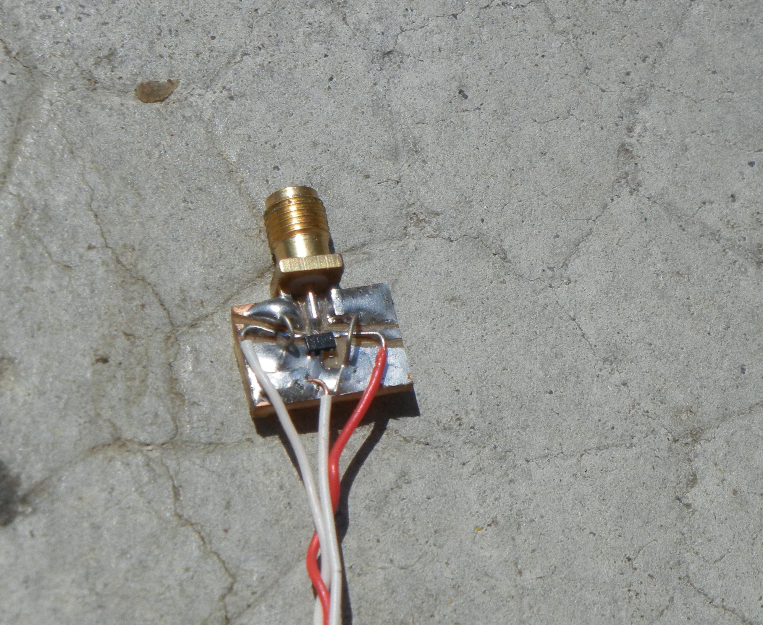
RF backscatter module
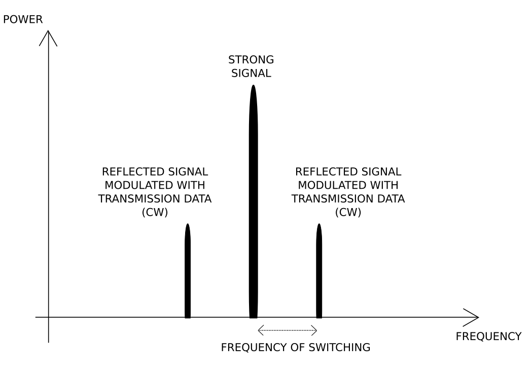
An RF transmitter module, that use strong RF signals to transmit data by partially reflecting it.
 Julien
Become a Hackaday.io member
Already have an account? Log in.
Just one more thing
To make the experience fit your profile, pick a username and tell us what interests you.
Pick an awesome username
hackaday.io/
Your profile's URL: hackaday.io/username. Max 25 alphanumeric characters.
Pick a few interests
Projects that share your interests
People that share your interests

 Raphael Valceschini
 Nicholas Amrich
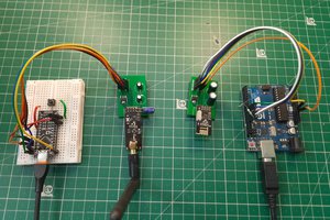
 ElectroBoy
 Ai-Thinker
I think you should see this EC I (cryptomuseum.com)
It is a backscatter device from the 60s era. I hope you can replicate it.