Julien
-
The next test
07/12/2018 at 09:06 • 0 commentsI need to find a better way to switch the two impedances. So I will try with a MOSFET, and also another model of pin diode, but new this time to avoid any problem.
When I will receive them, I will be able to first test with a VNA that I have a consistent impedance switching, and then I will start to make a frequency generator and do the first RF backscatter experiments.Then I will be able to choose the best uC suited for this task. When I receive the parts, I will post again.
-
First test
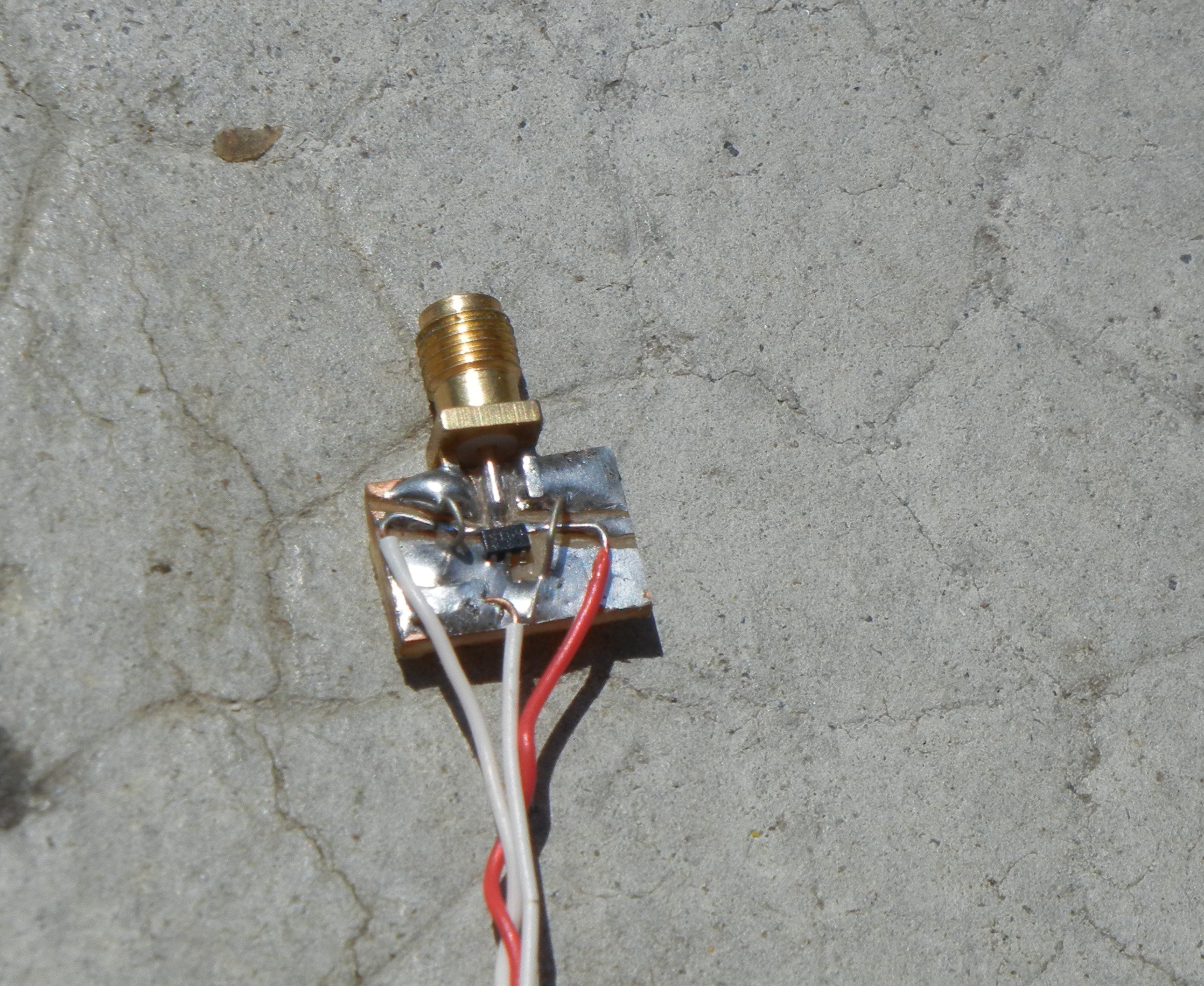
07/11/2018 at 11:37 • 0 commentsToday I built a quick pcb with a pine diode and an SMA connector. The pin diode switch between a sort and an open circuit.
The pine diode I used was not the best choice, but the only I already have in my pile of junk. I tested it with my VNA, to metter the impedance change.
It's a big fail. My two impedances are near the same ... the impedance doesn't change from a short...
Maybe this IC was damaged, because it was unsoldered on junk, maybe also I heated it too mutch, or even it's because I missed to add a DC blocking capacitor.
![]()
![]()
-
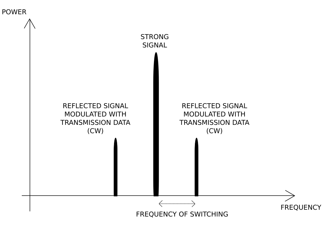
How it works
07/10/2018 at 20:48 • 0 commentsSo basically, when reflecting a signal, there is two images, one F=SwitchingFreq+CarrierFreq and one F=SwitchingFreq-CarrierFreq
Maybe I will try to filter one of the image with a stub filter in the future (but losses might be a problem).
![]()
-
The plan
06/24/2018 at 21:25 • 0 commentsThe short term goal to test this module, is to use it as a ham radio beacon. So it will only need to send the same centence in CW.
The differents steps to archive this goal will be :
- Experiments with backscatter
- Selecting a pin diode or a mosfet
- What frequency is the best ?
- How mucth power is needed ? What are the best "natural" source of RF power ?
- Microcontroller
- What peripherials are the best to drive the backscatter part efficiently ?
- How low power ?
- Experiments with backscatter
RF backscatter module
An RF transmitter module, that use strong RF signals to transmit data by partially reflecting it.