Greg
Greg-
Fusion 360
08/01/2018 at 16:18 • 0 commentsThis has been the biggest project I've done yet with Fusion 360, and I've learned quite a lot.
- Always start each new document with "Create -> New Component". This lets you separate your model into pieces-- each with its own history-- and move them around separately.
- Copy and paste components to make multiple copies of a component. This allows you to make design changes to the original component, and have all the copies of it update automatically.
- Use the CAM tool to output profiles for laser cutting. That's what I did for the "plates" between the blades.
- McMaster Carr puts 3d models of their entire catalog online, which you can easily import into Fusion 360. This is amazing.
I still have a bunch to learn. When doing a design, do you put the nuts and bolts in, or is that too much detail? Should I be setting up joints?
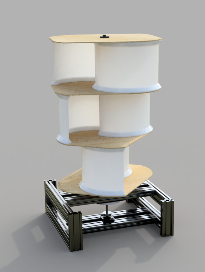
Also, Fusion 360 has a really nice rendering engine:
-
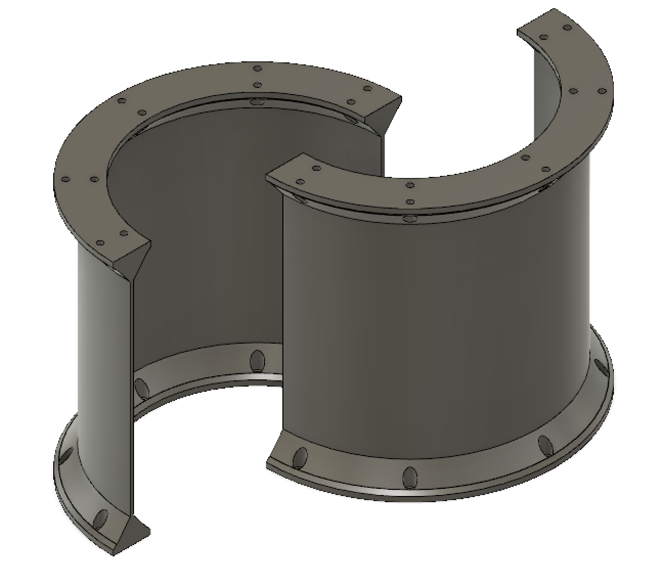
New Blade Design
07/30/2018 at 04:09 • 0 commentsGreg says Savonious blades work best when they can "spill" from one to the other through the axle, so I made a new blade design which allows the some overlap between the blades. Another advantage of this is that it lets you print larger blades if you want.
![]()
The blades are self-symmetrical, and interchangeable.
Like before, they're parametric:
- Blade Diameter
- Blade Height
- Blade Thickness
-
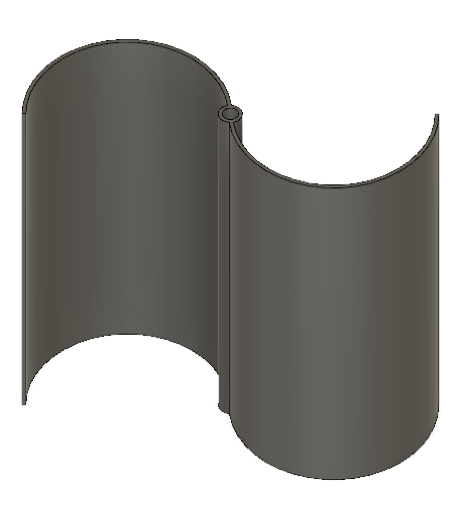
Parametric Blades
07/13/2018 at 20:50 • 0 commentsSince the limiting factor for the size of the blades is the size of your 3D printer's print bed, I designed this parametrically as well.
It supports these parameters:
- Blade diameter (from tip to tip)
- Blade height
- Shaft diameter
- Thickness of the blade.
As our savonious design requires three of these, I figured it would be smart to design it such that
![]()
-
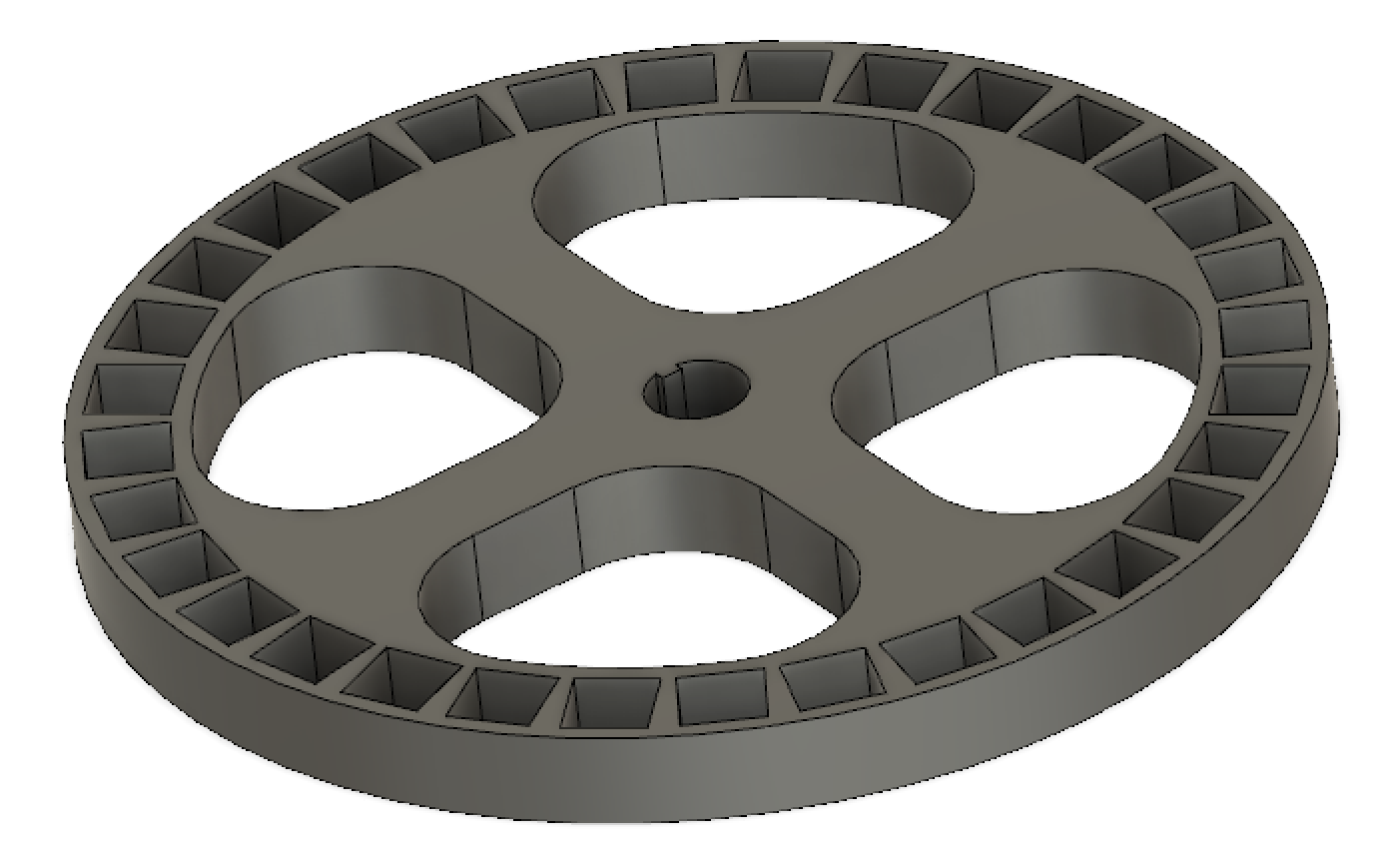
Parametric Rotor
07/13/2018 at 01:45 • 0 commentsOne of our goals for this project is to make it as parametric as possible, so we can easily adjust the specs as we experiment to get the power output we need.
So, I designed a Parametric Rotor in Fusion 360. It has several parameters:
- Number of Magnets
- Size of Magnet (assumes square magnets)
- Diameter of the magnet ring
- Diameter of the hole for the shaft.
For flexibility, I've been designing this with both laser cutting and 3D printing in mind, and this file can be used to generate a DXF for lasercutting, or an STL for 3d printing.
![]()
I don't think my key system there will work well for actually tightly securing this to the axle. I need something with a setting screw.
-
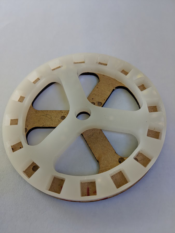
First stator and rotor prototypes have arrived
07/13/2018 at 00:44 • 0 commentsLaen has designed a 16 magnet rotor to work with the original PCB stator. He designed it in Fusion360 and cut it out on his laser in an afternoon.
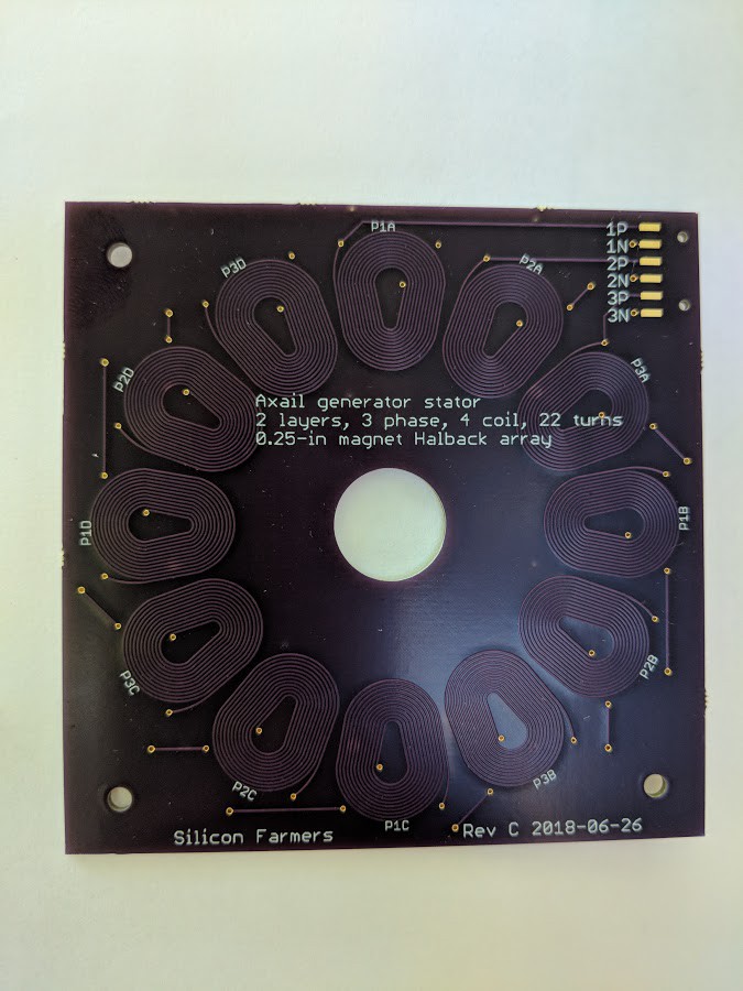
![]() The initial stator design, "Rev C", PCB has arrived from OSHPark. I need to test the performance of this design so I have an order of magnitude guess on what the design parameters should be for the next version.
The initial stator design, "Rev C", PCB has arrived from OSHPark. I need to test the performance of this design so I have an order of magnitude guess on what the design parameters should be for the next version. ![]()
The initial order of mechanical parts has arrived from McMaster-Carr. Gluing the magnets into place and attaching the rotor to a shaft is easy, but I only bought 2-foot shafts, so its a bit unwieldy for a lab bench setup. I am working on a 3D printed structure to hold the stator in place above the rotor. When that is done, I can do some initial tests of performance by turning the shaft by hand and measuring the resulting voltage across a known load.
DIY Savonious Wind Turbine
A small wind energy harvesting system for charging batteries to power your projects when solar is not an option
 The initial stator design, "Rev C", PCB has arrived from OSHPark. I need to test the performance of this design so I have an order of magnitude guess on what the design parameters should be for the next version.