Psycho
-
Onboard temperature
07/16/2018 at 09:11 • 1 commentBeen a while now, it's summer, work at the highest point, available time has gone down for me a little. But not enough to stop me. So why don't you guys have a guide yet? Because I decided to add an element to the pcb, as an option for people that don't have a Netatmo :)
Yes, I added a socket to connect a temperature sensor, I chose the Adafruit MCP9808. You could also pretty easily use the bigger version that has humidity and pressure sensor on it.
I did not yet print this PCB for test but shall do this this week
![]()
-
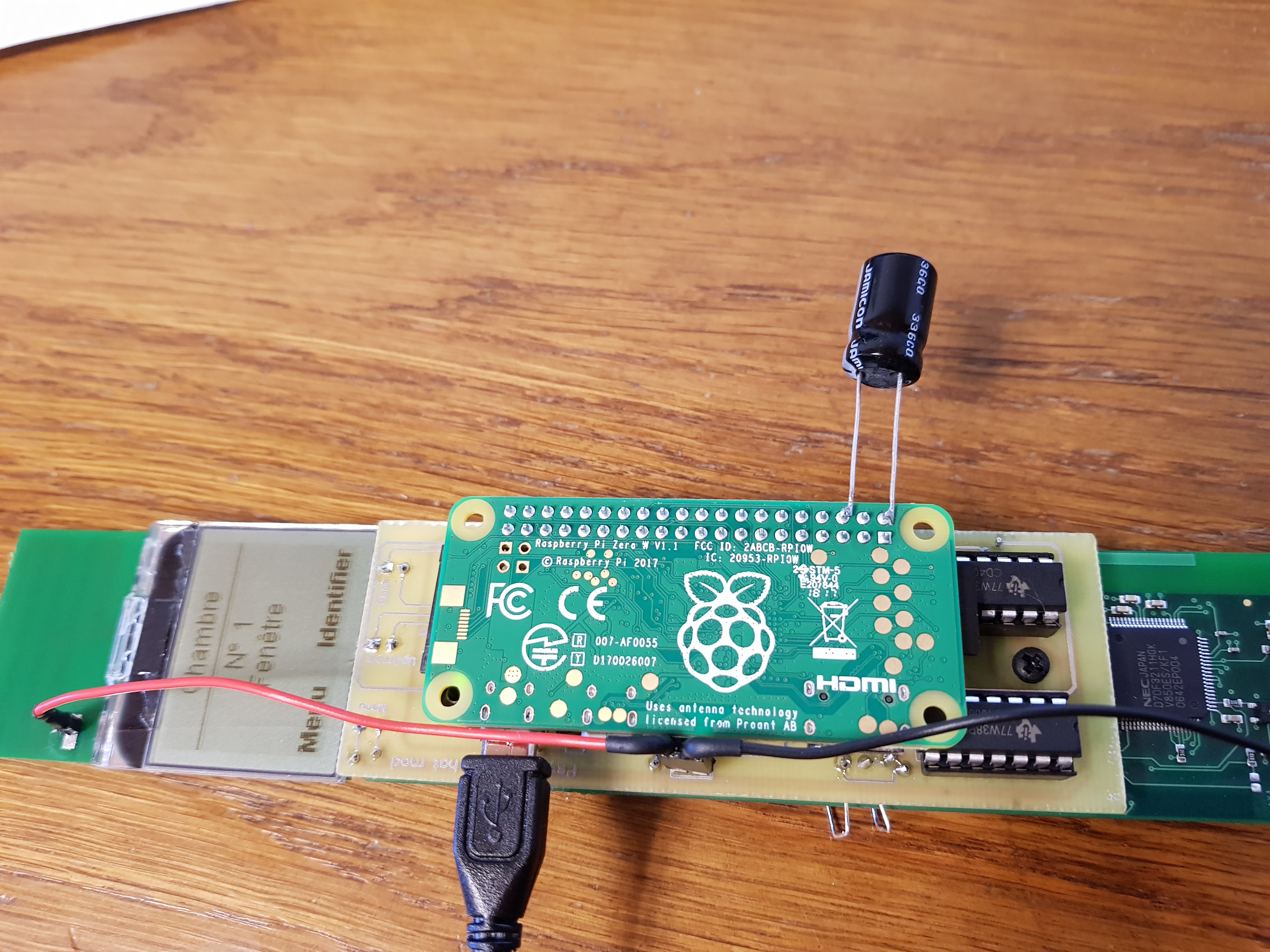
New and hopefully final
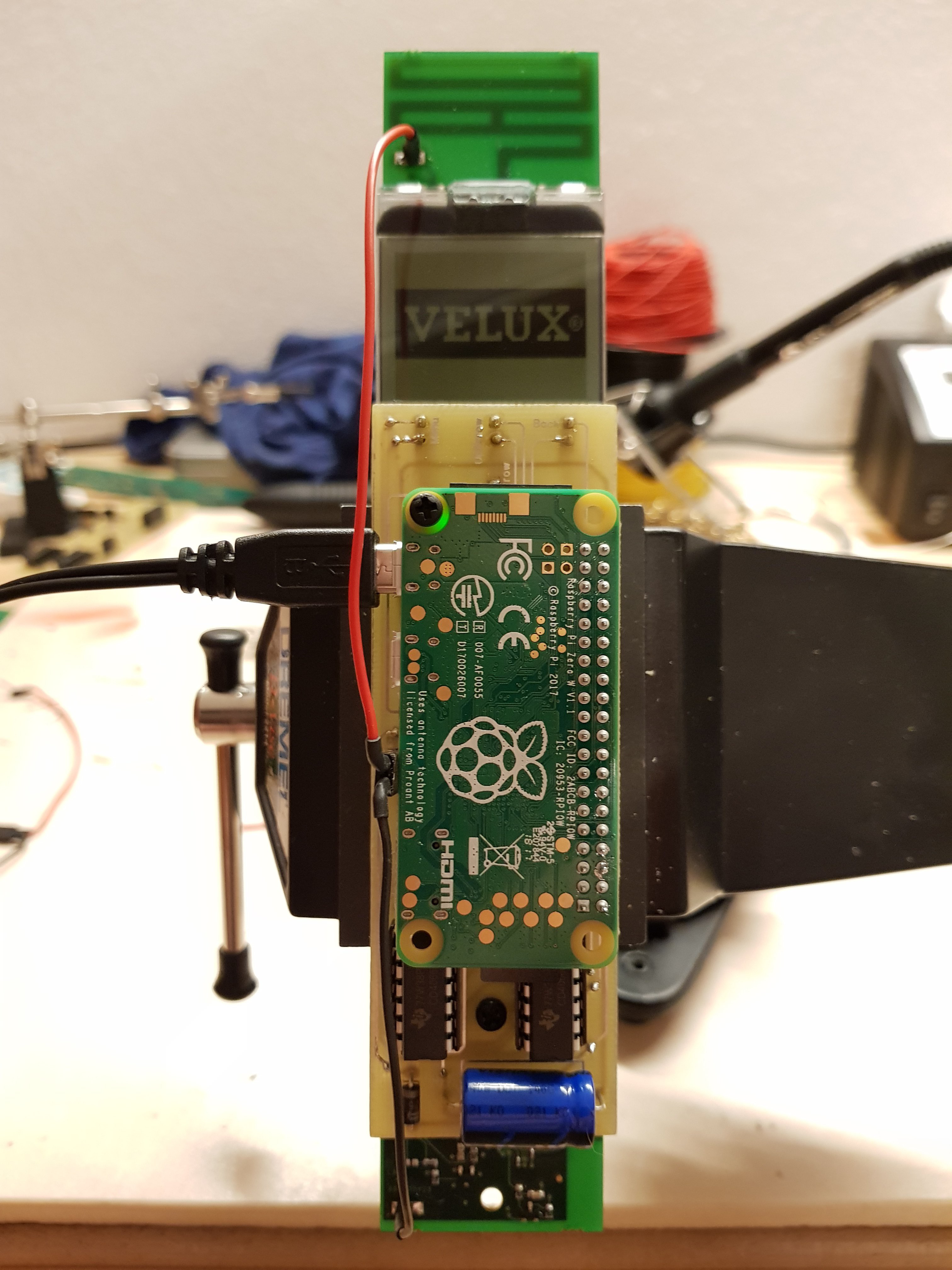
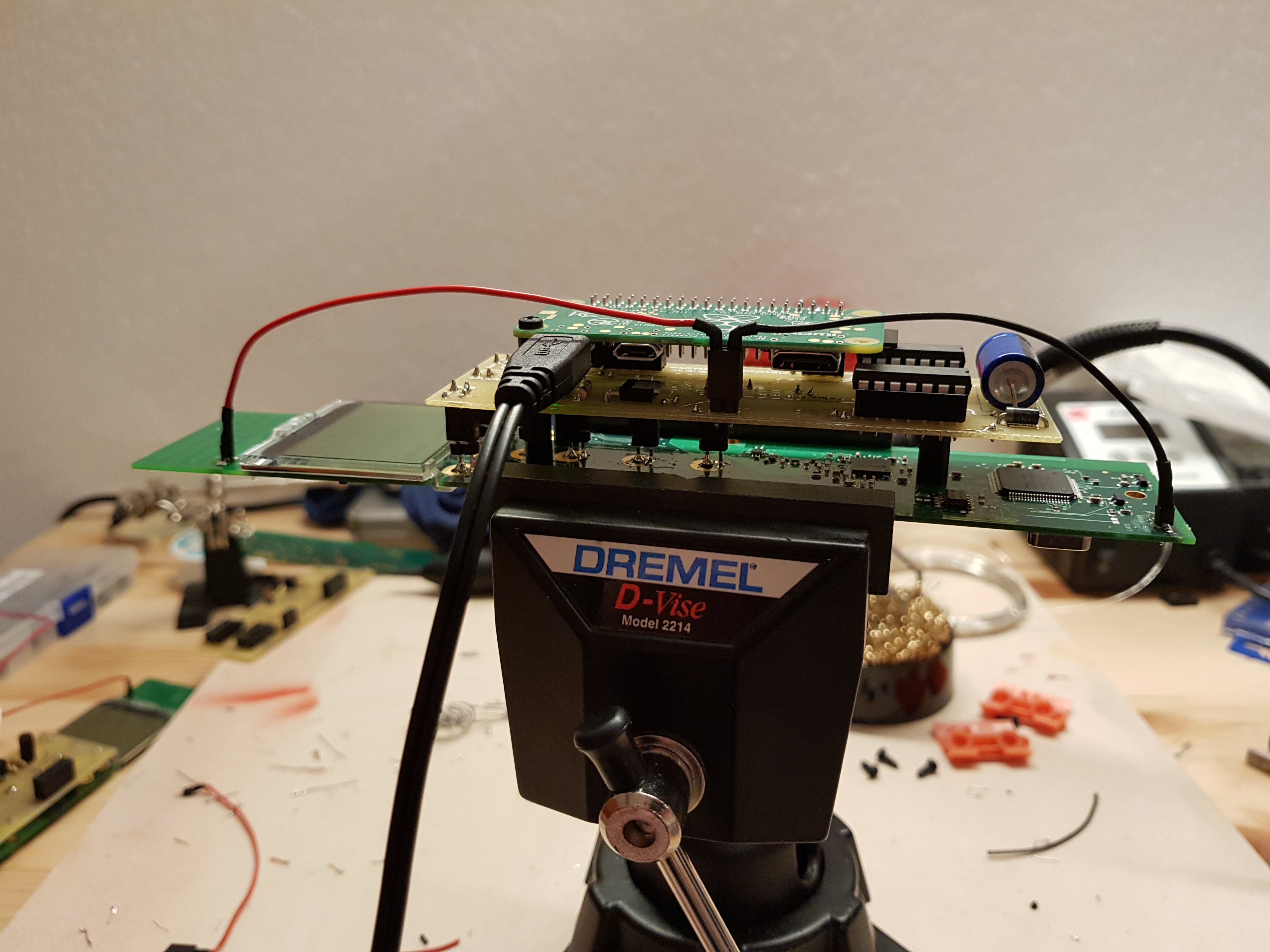
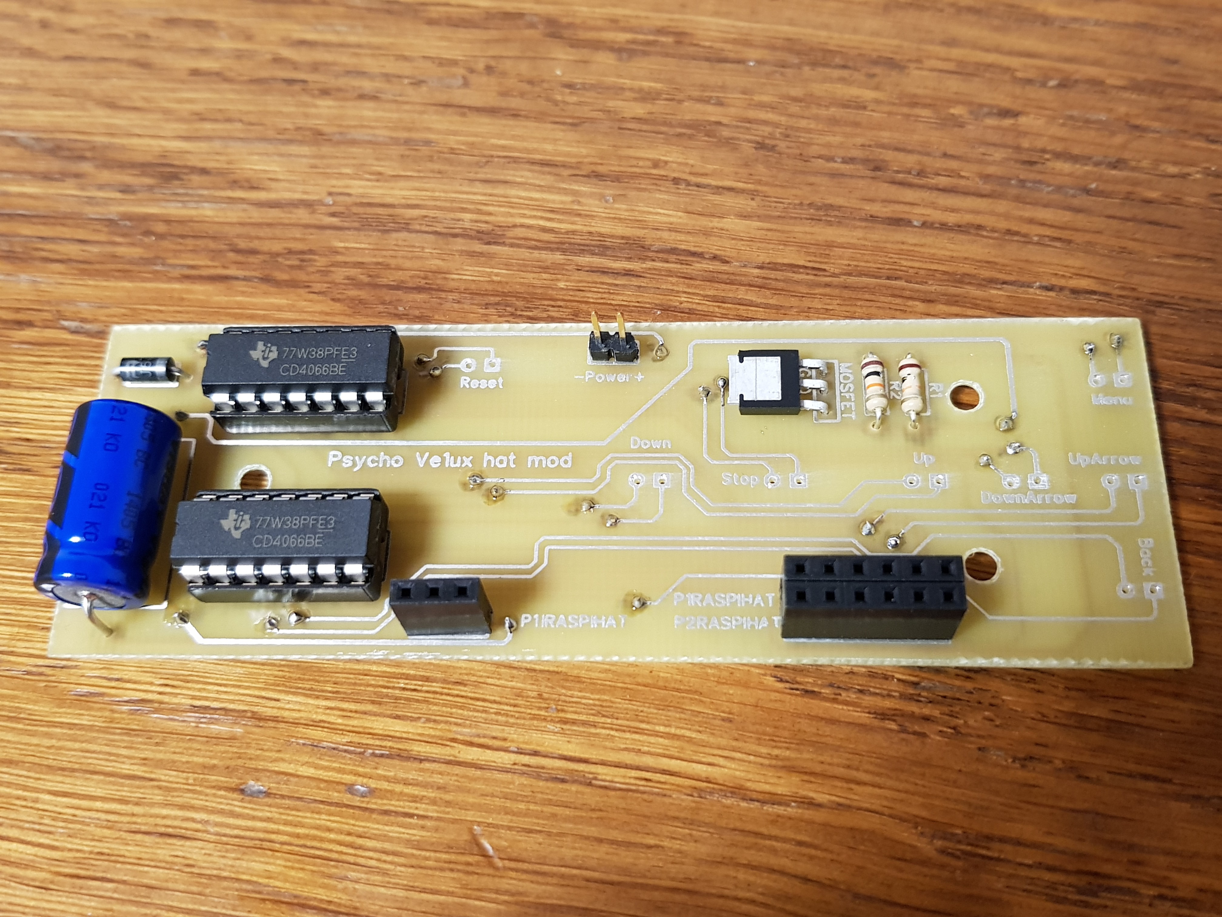
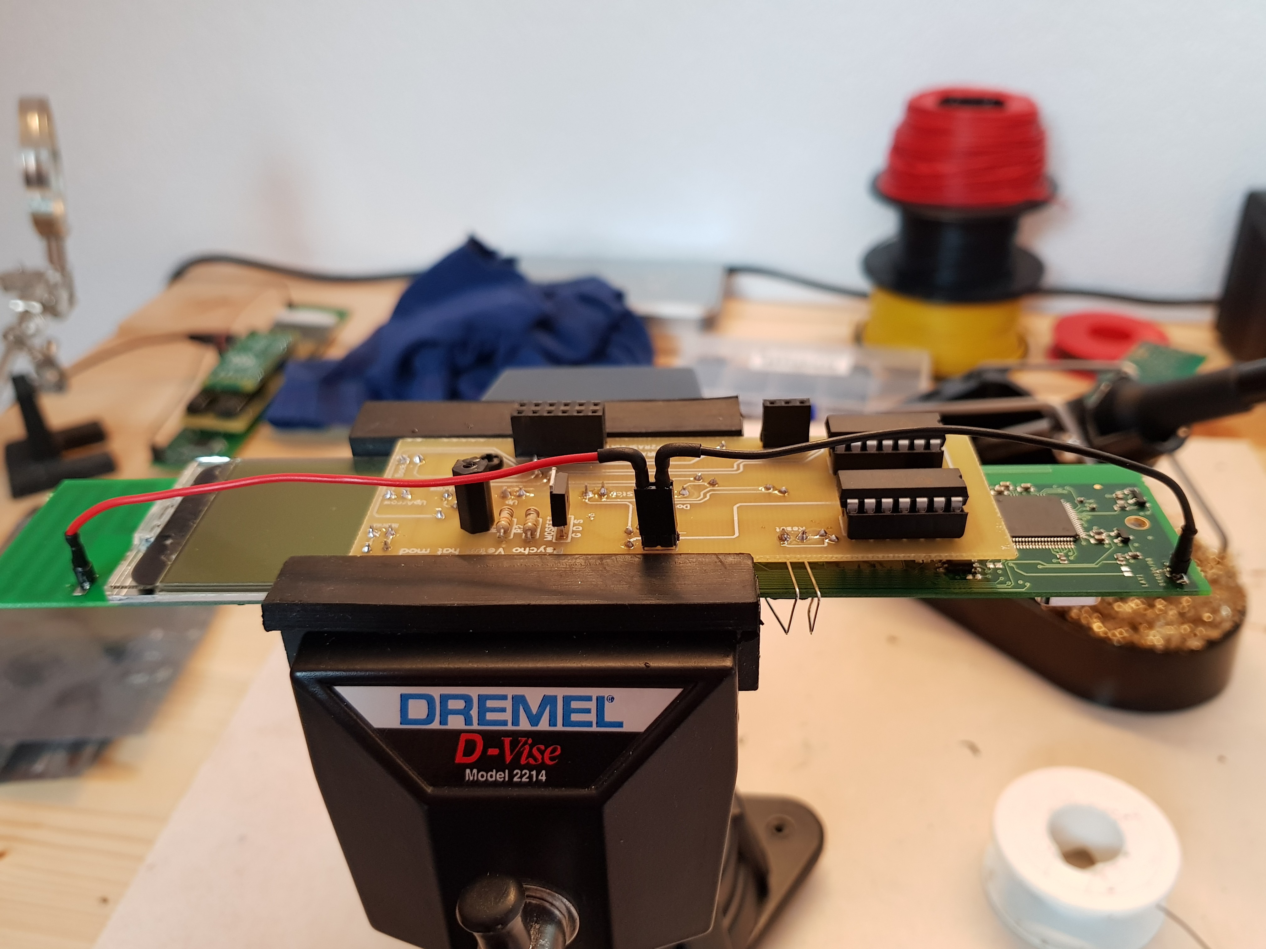
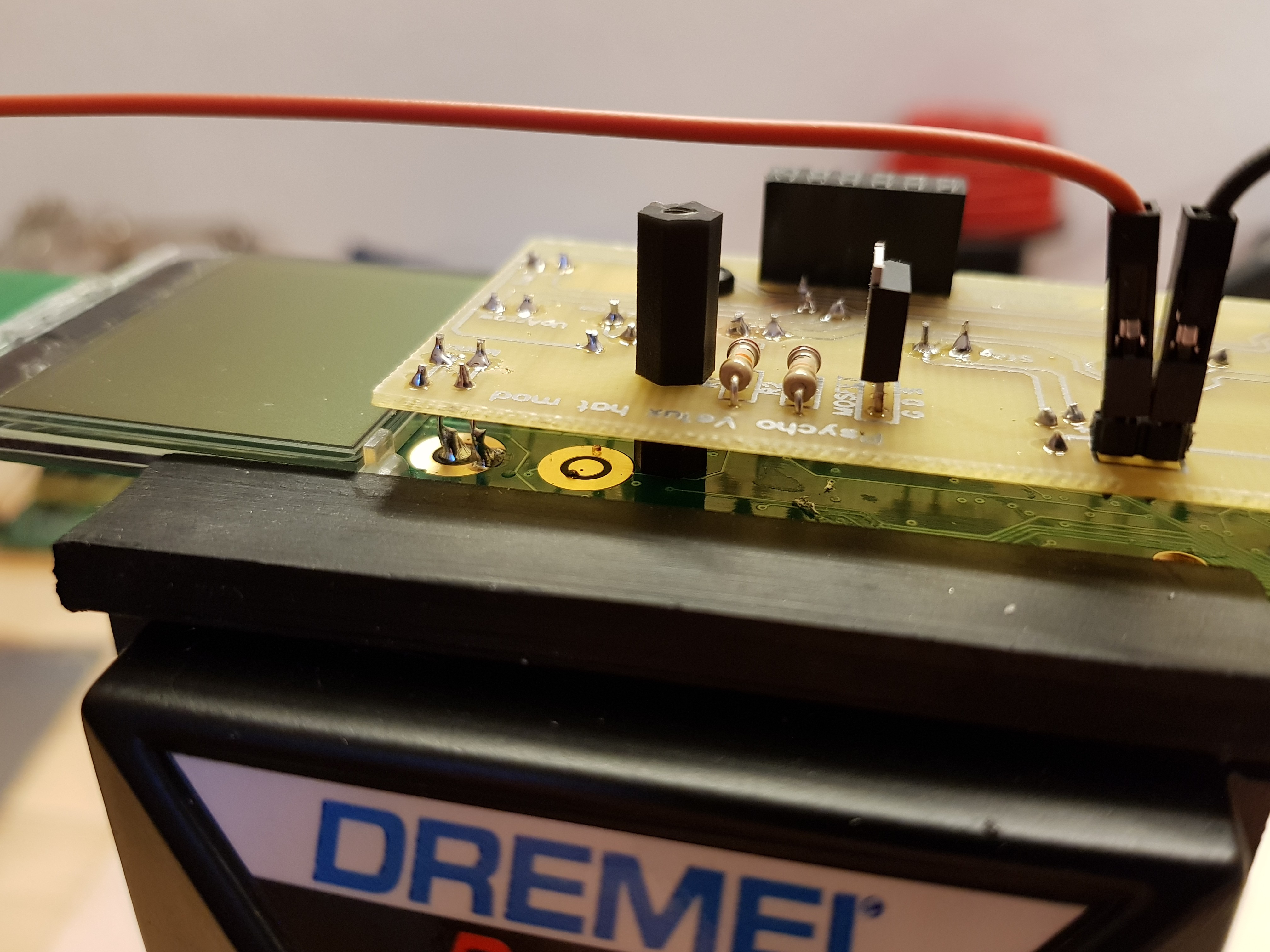
06/30/2018 at 17:59 • 0 commentsThe new PCB was printed yesterday evening and I did solder the components right after. I Changed the approach to connect the mod to the remote and went for pin headers, allowing easy disassembling of the mod if needed. The capacitor does a really good job and the diode does what it needs by dropping the voltage for the remote. Expect the building guide anytime soon
![]()
![]()
-
New PCB ready
06/29/2018 at 19:16 • 0 comments![]()
-
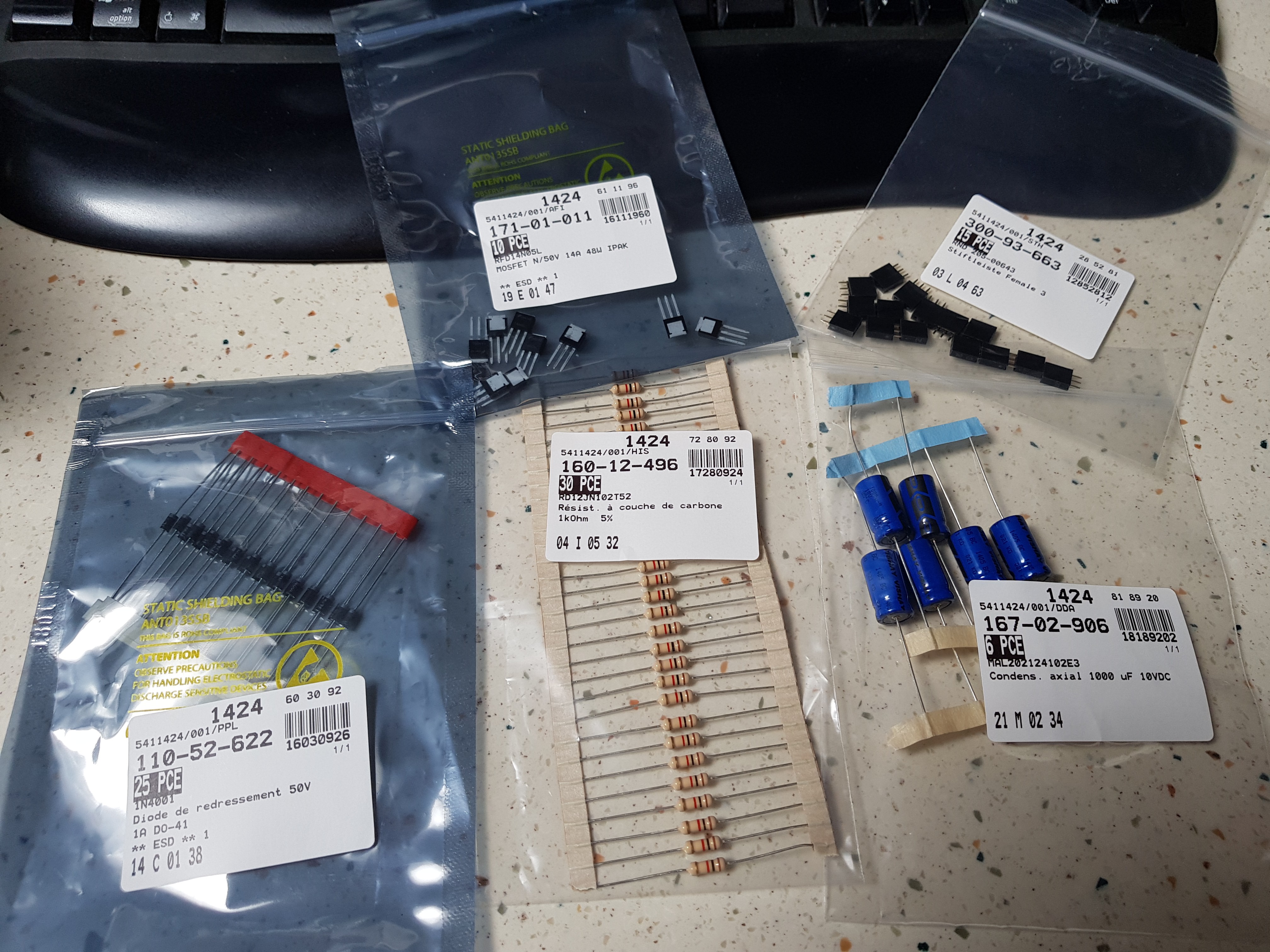
New components arrived
06/29/2018 at 09:40 • 0 commentsNew components just arrived. I'll redesign the pcb this evening as some measurements providd by the reseller were wrong...
![]()
-
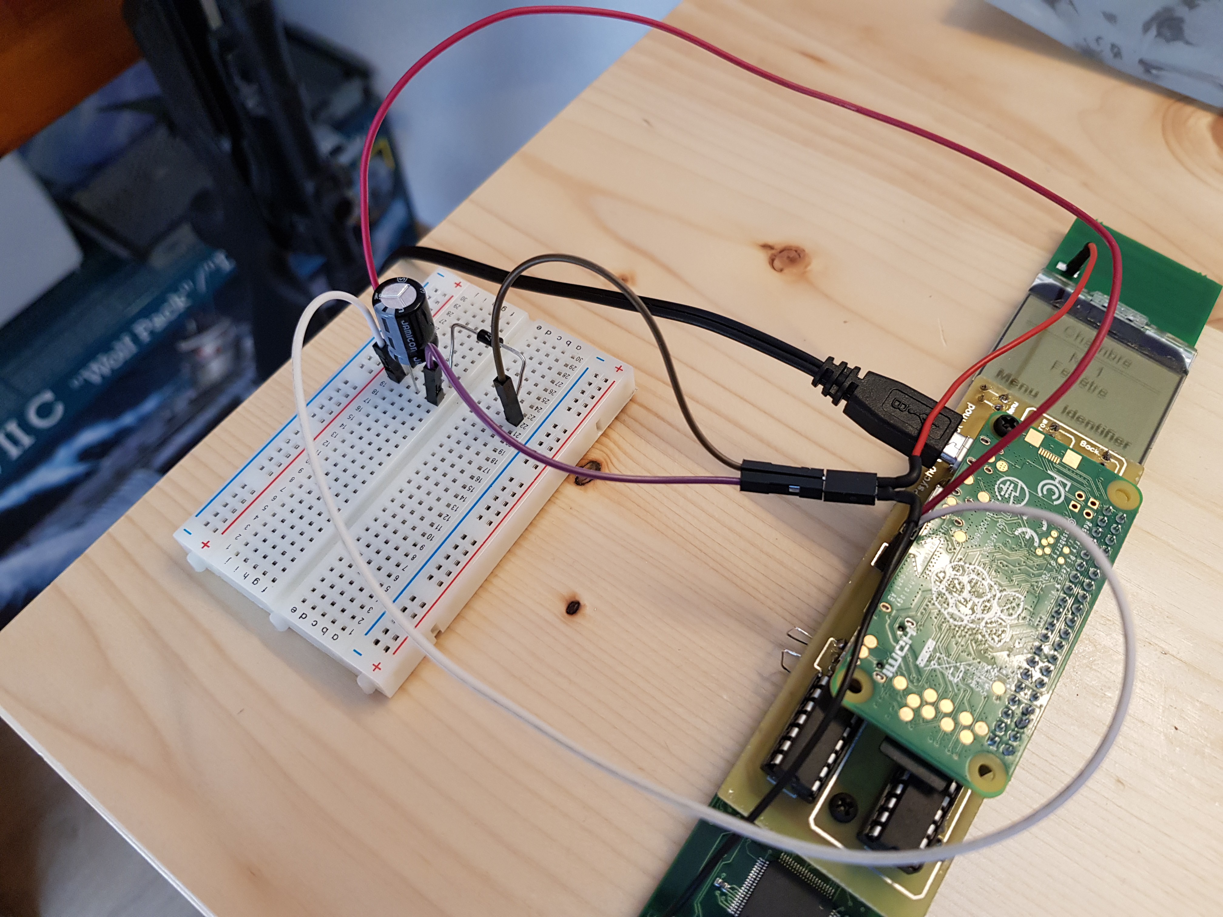
Breadboard test of new components
06/28/2018 at 13:19 • 0 commentsTesting the addition of a diode and a capacitor before making the new pcb. So far ok, been running over 24 hours with actions to handle at least 3 times an hour.
![]()
-
Dropping voltage
06/27/2018 at 17:24 • 0 commentsThe Velux remote is normally powered by 3 1.5v batteries but the pi outputs 5.2v for it. It's a bit too make and the remote occasionally cries. I decided to add a diode to reduce the voltage. I'm currently redesigning the pcbs.
-
Issue identified
06/27/2018 at 14:38 • 0 commentsAfter losing my day wondering why nothing worked anymore after the connector change an issue was detected. Having neat wires, soldered instead of jumpers demanded to much current for the remote to handle. It was working when connecting the remote with jumpers to the raspberry pi zero, but not when using it as a hat. After trying for hours alone, I asked my friend mpbs again for his advises and he told me to add a capacitor. I did it, but it wouldn't work... Trying again and again, with or without jumpers until, changing the pi zero for a new one and adding a capacitor! It works! Well, we had clearly 2 issues, the first one the pi was dead, prolly from touching the component between the usb ports yesterday, and having new proper wires was too demanding! I will redesign a new pcb and add the capacitor
![]()
-
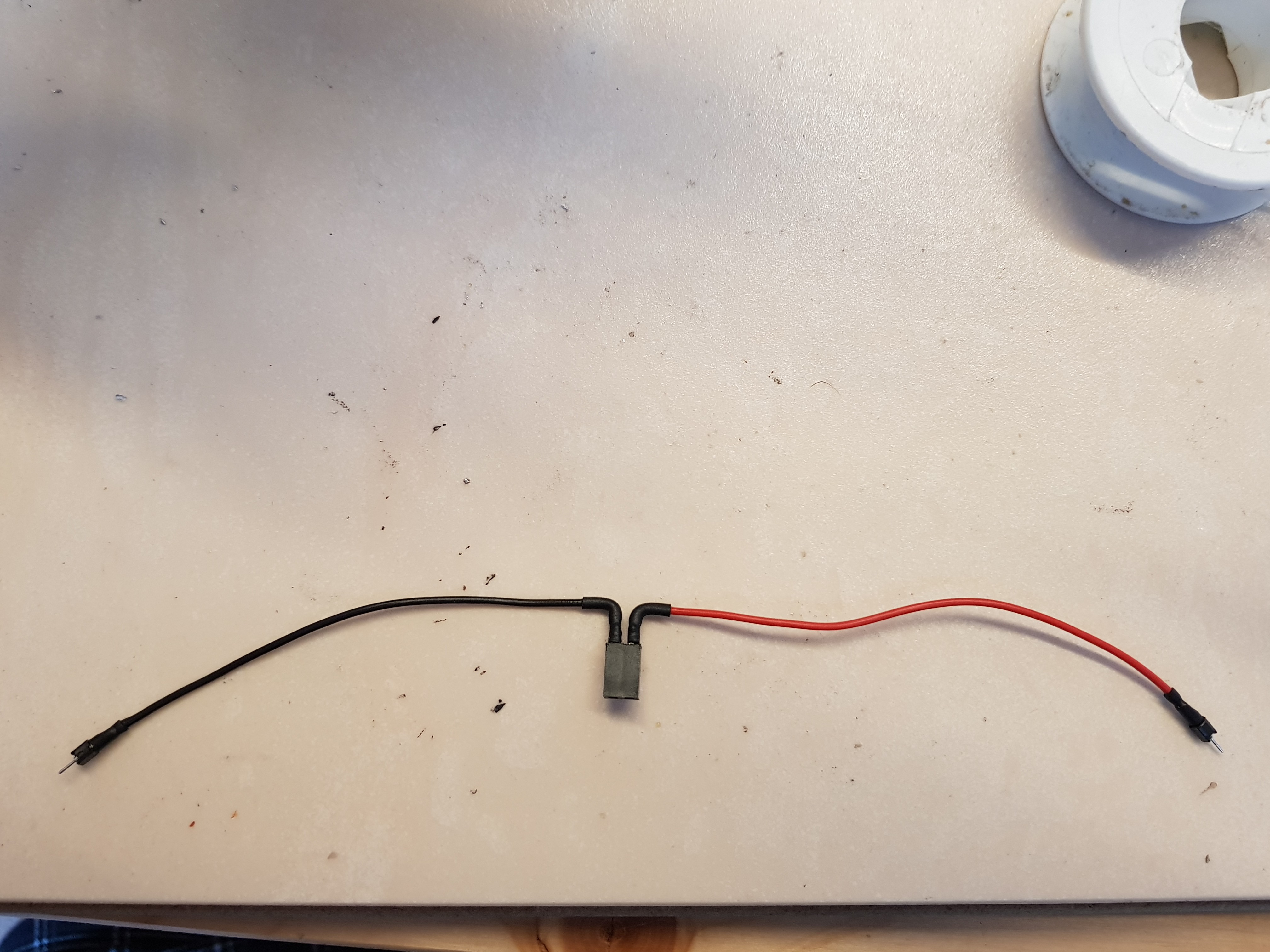
Better power connector
06/27/2018 at 10:01 • 0 comments![]()
![]()
-
Issue identified
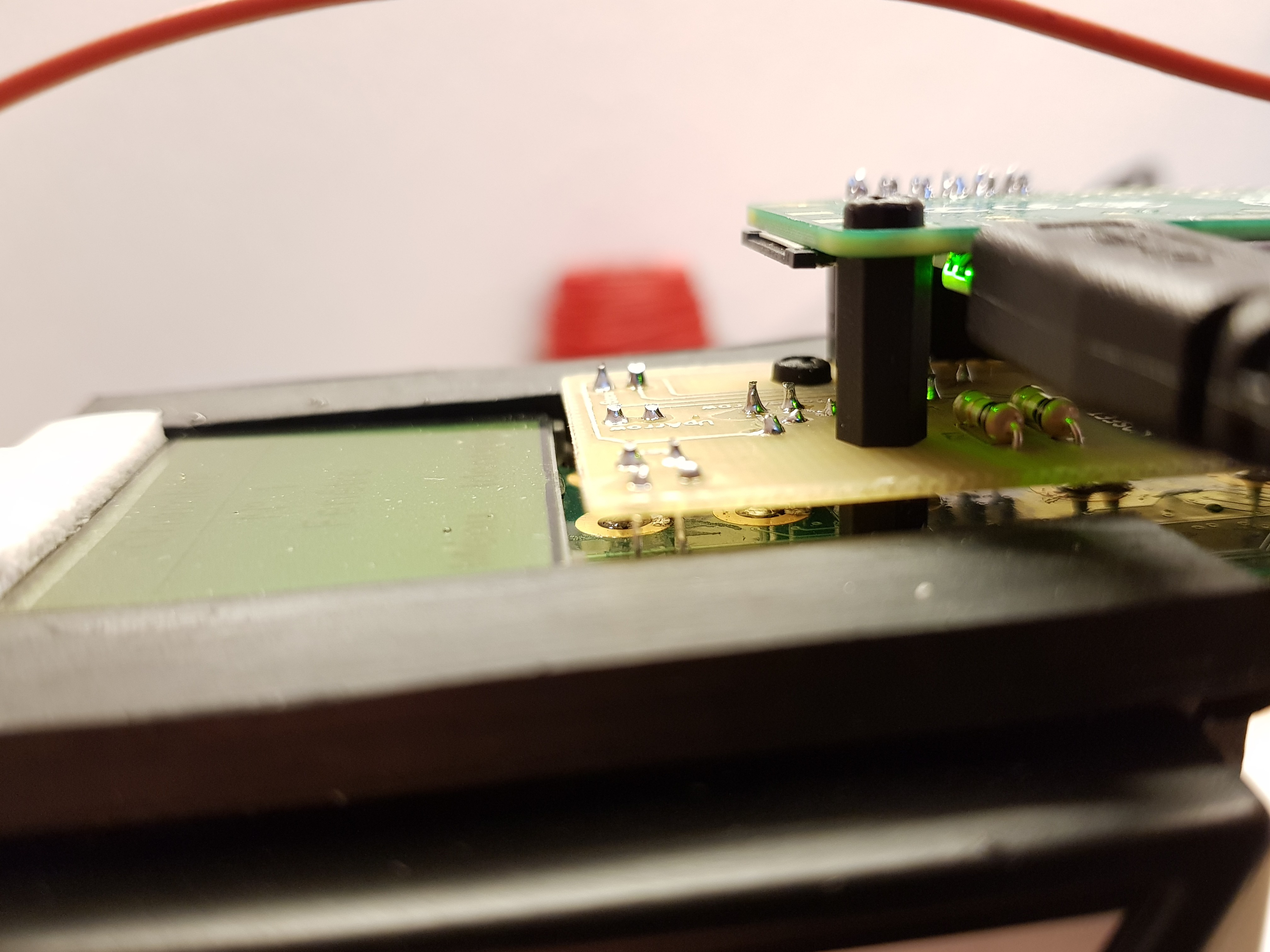
06/26/2018 at 19:14 • 0 commentsFound an issue where if you plug a raspberry pi zero on the mod, plug it's power cord, it might slightly bend the pi down. The mosfet drain ends up touching the component between the two usb ports on the raspberry, shorting the raspberry and at the end destroying the mosfet.
Solution is rather easy, adding a spacer between the mod and the pi to forbid anything to move. Quite luckily, really, the pi zero hole lines up perfectly with the mod hole. What a lucky guy I am!
![]()
![]()
-
Milestones
06/23/2018 at 06:54 • 0 commentsFuture milestones
- Web interface for setup
- Install instructions
- Full guide for newbies
- Switching between standalone, network device or snips satellite
Current milestone
- Run full install as standalone on pi 3b
- Proposing pcb printing services
Past milestones
- Printing PCB
- Designing circuitry
- Connect
- Trying to handle remote buttons with proto board and relays
Voice control for Velux
Hacking Velux remote with a hat to enable voice control over a raspberry pi powered by Snips