 Javier Betancor
-
1Power Generation Setup
Components needed:
- 1 x Stepper Motor (17HS4417)
- 1 x JSP XPH-4 male + female + inserts
- 4 x M3 screws
- 1 x Aluminium U channel for the Motor Bracket
- 1 x 3D-printed Spur Gear
- 1 x 3D-printed Pinion Gear
- 1 x M3 Allen Grub Screw
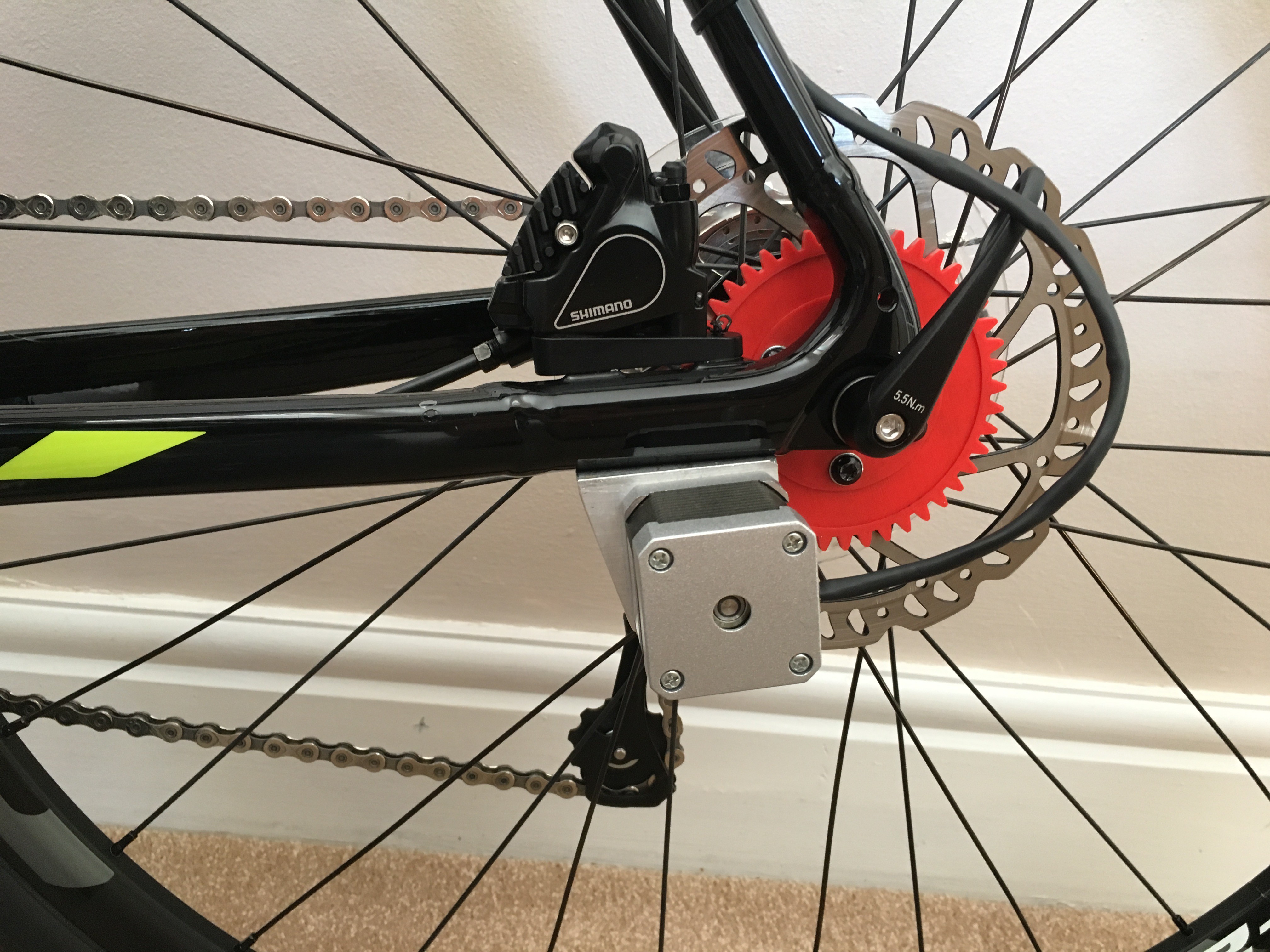
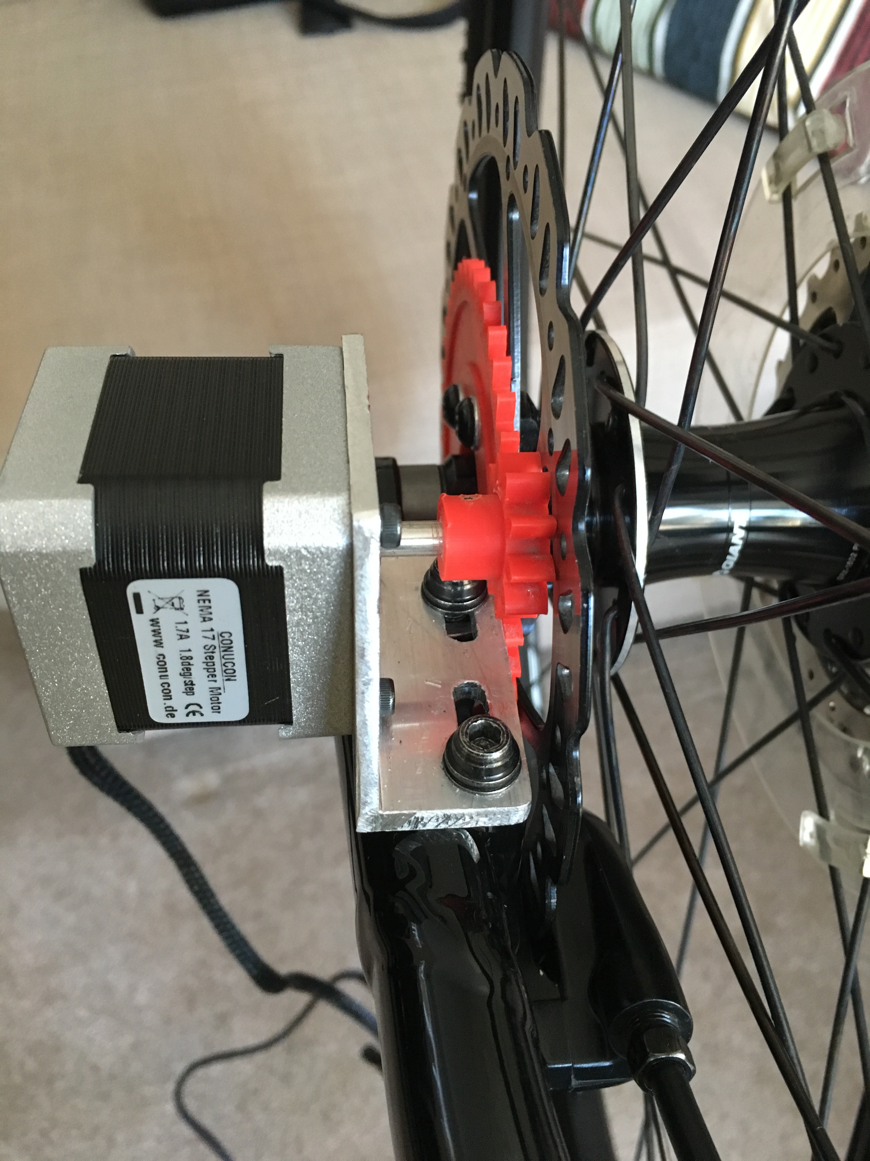
Assembly all the aforementioned components to create a unity and attach it to the rear/front brake disc. You will need a crimping tool for the JSP plug, unless it is already included.
Please, be aware that what it is being shown may differ from your case. It should look like this:
![]()
![]()
-
2Smart Lighting System Setup
Components needed:
- 1 x 10x10 RGB LED Matrix (WS2812B)
- 3 x Light Dependant Resistor (LDR)
- 1 x 3D-printed Front Light assembly
- 1 x 3D-printed Rear Light assembly
- 5 x M3 screws + nuts for the headlight and rear light
- 3 x JSP 2.54mm XPH-3 housing (male + female + inserts)
Please, make sure that all printed parts will fit in your bike, so make some measurements first. I also recommend you to solder all wires for the LED matrix very carefully and taking your time. It should look like this when you finish:
![]()
It should i;ike the image below when all components are assembled:
![]()
-
3eBox Setup
Components needed:
- 1 x 3D-printed eBox assembly
- 2 x 3D-printed Power Bank Housing
- 1 x 3D-printed eBox Mounting Bracket
- 1 x Strip Board
- 1 x Relay (SRD-05VDC-SL-C)
- 2 x Diodes (1N4007)
- 2 x USB 2.0 to Micro USB cable (1m)
- 2 x Power bank
- 1 x Single Solid Core (SSC) Black wire (0.6mmx1m)
- 1 x SSC Red wire (0.6mmx1m)
- 1 x SSC Green wire (0.6mmx1m)
- 1 x SSC Yellow wire (0.6mmx1m)
- 1 x SSC Orange wire (0.6mmx1m)
- 1 x SSC Purple wire (0.6mmx1m)
- 2 x M3 screw
- 1 x Rubber Sheet (250x250x1.5mm)
- 2 x M3 Threaded brass insert
- 8 x Neodynium Magnet Disc (3x20mm)
- 1 x Stainless Steel Rod Bar (200x2mm)
- 2 x Blue LED
- 2 x 220Ohm Resistor
- 1 x DPDT Switch
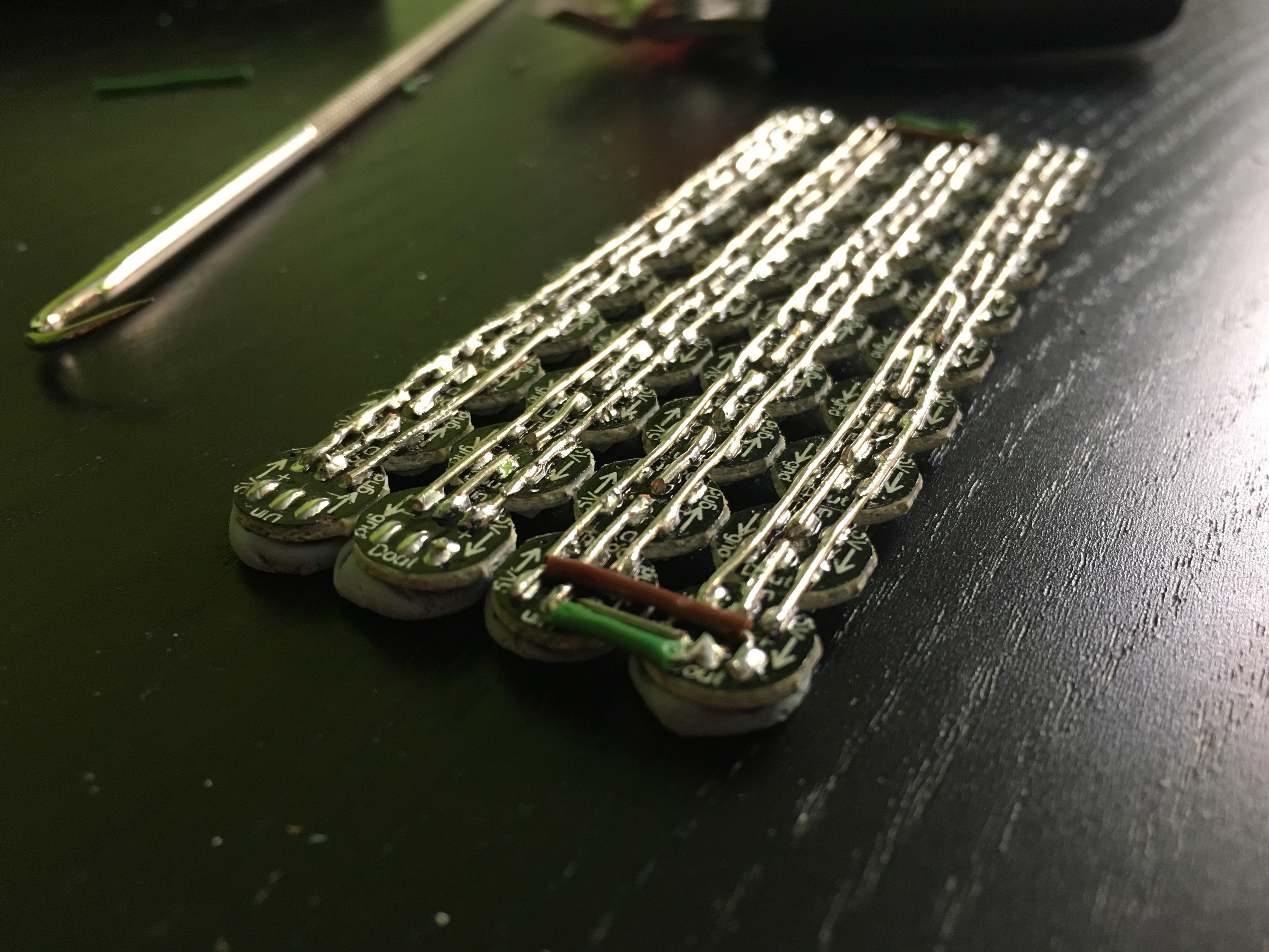
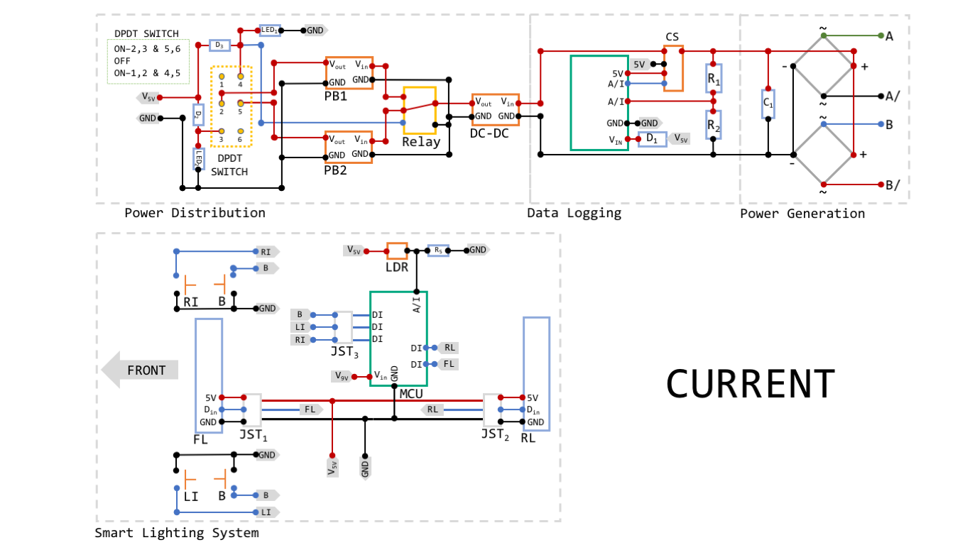
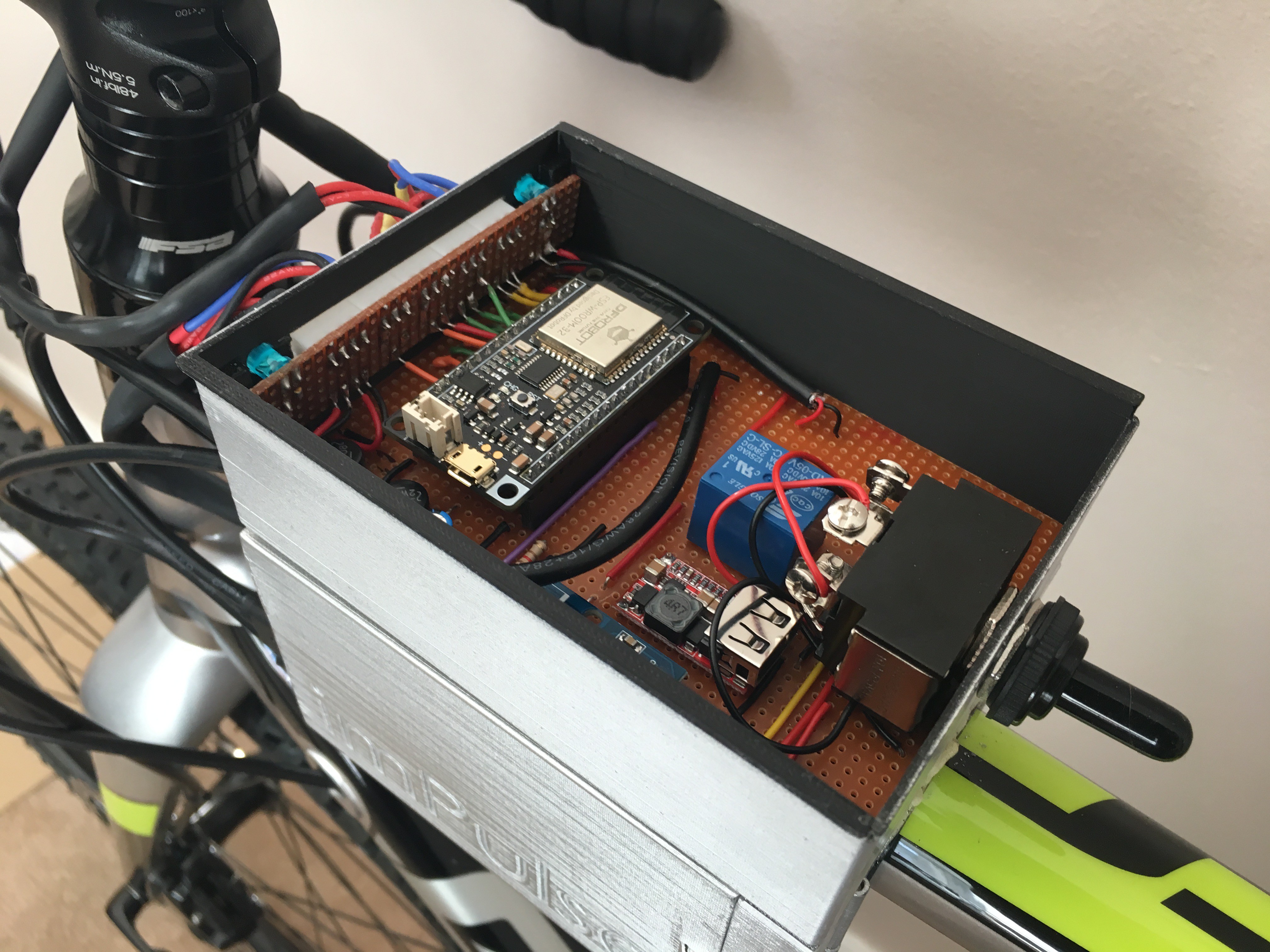
Follow he diagram below for the soldering part. Please, make sure that the perforated board can be trimmed, so allow some tolerance for fitting purposes.
![]()
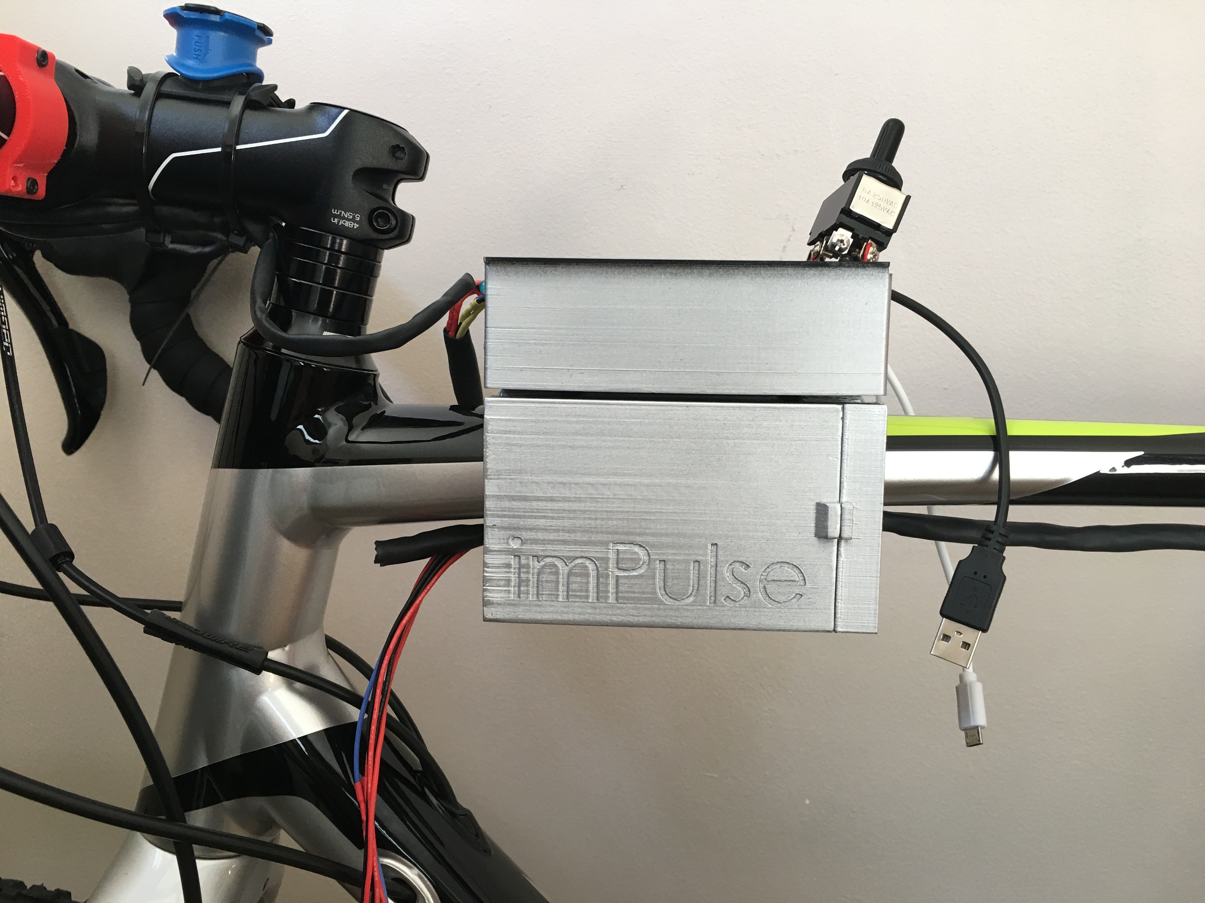
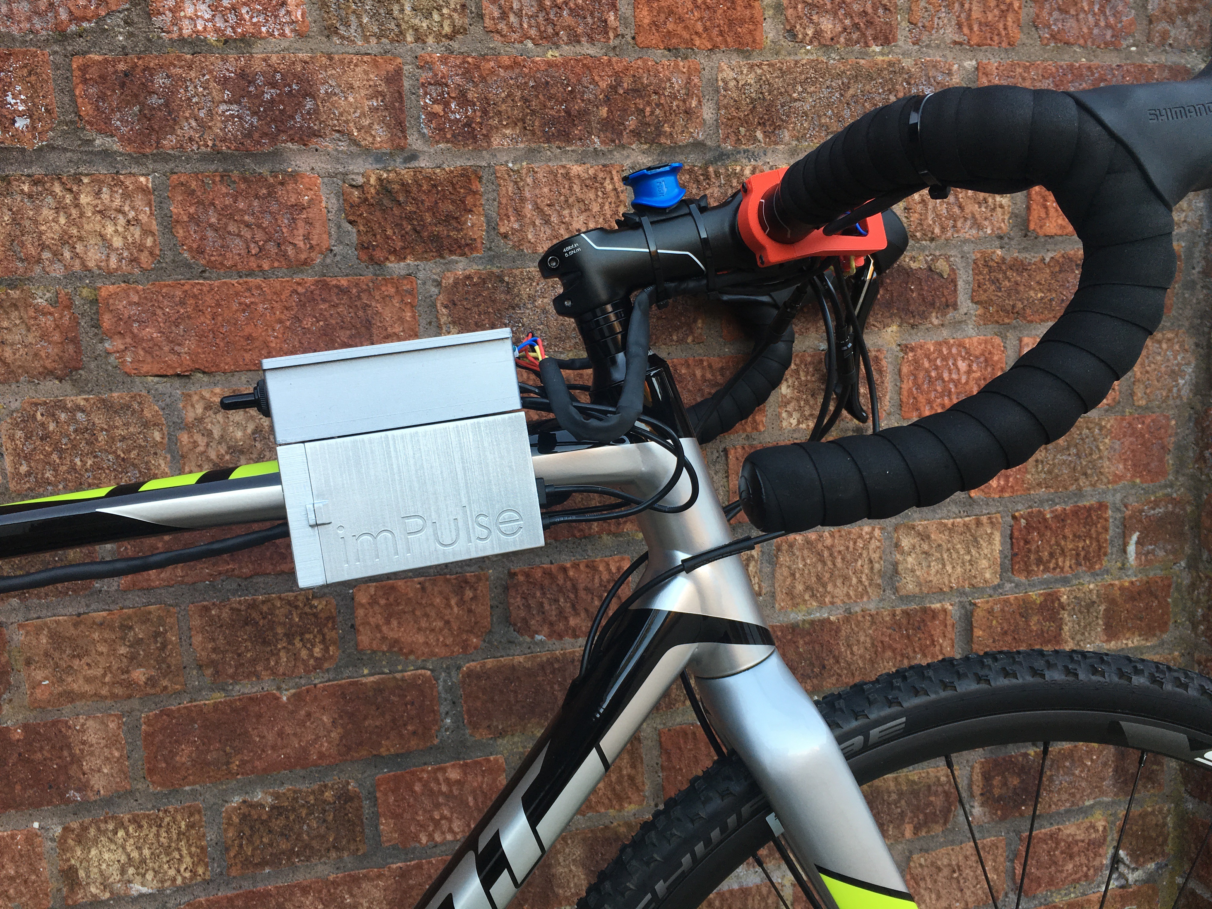
Again, please make some measurements first for the CAD models. The final result should look like this:
![]()
![]()
-
4Wiring Harness and testsing
Components needed:
- Black Heat Shrink Tube 3:1 (1m x 10mm)
- Black Heat Shrink Tube 3:1 (2m x 5mm)
- 1 x Blue Silicon AWG 22 wire (5m)
- 1 x Red Silicon AWG 22 wire (10m)
- 1 x Black Silicon AWG 22 wire (10m)
- Cable ties (200mm, 100pcs)
- Cable ties (100mm, 100pcs)
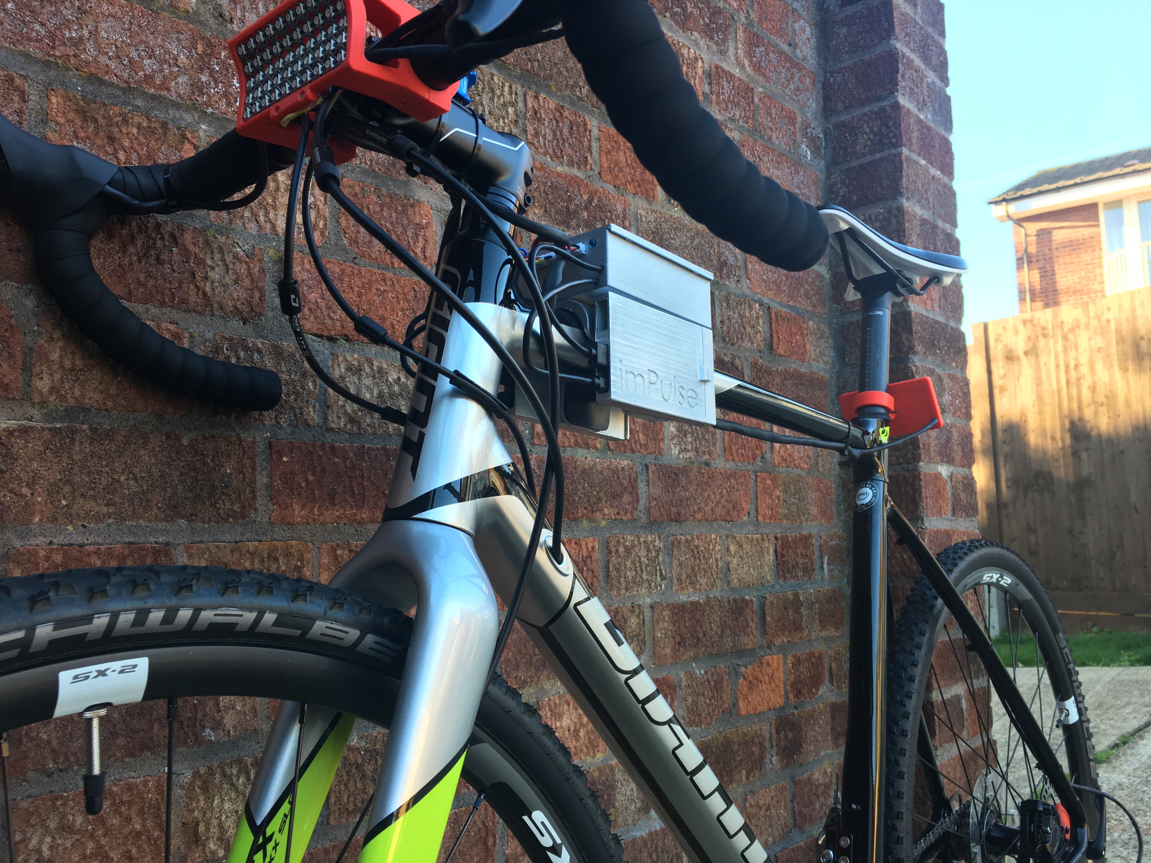
I have some experience doing wiring in race cars. My advice, always leave more wire than expected as there is always a turn here or a bend there. It is a very important part, as this needs to look professional and tidy. On the other side, it should be easy to split and rearrange. The final result should look like this:
![]()
![]()
imPulse
Energy harvesting alternative for bikes including data logging, smart lighting system and power distribution board for power banks

Discussions
Become a Hackaday.io Member
Create an account to leave a comment. Already have an account? Log In.