-
Wiring Harness Stage
10/18/2018 at 07:47 • 0 commentsThis could be a very tricky part depending on your bike. Components needed:
- Black Heat Shrink Tube 3:1 (1m x 10mm)
- Black Heat Shrink Tube 3:1 (2m x 5mm)
- 1 x Blue Silicon AWG 22 wire (5m)
- 1 x Red Silicon AWG 22 wire (10m)
- 1 x Black Silicon AWG 22 wire (10m)
- Cable ties (200mm, 100pcs)
- Cable ties (100mm, 100pcs)
- Soldering iron + soldering material
- Glue (e.g. super glue)
- Set of screwdrivers
- Heat gun
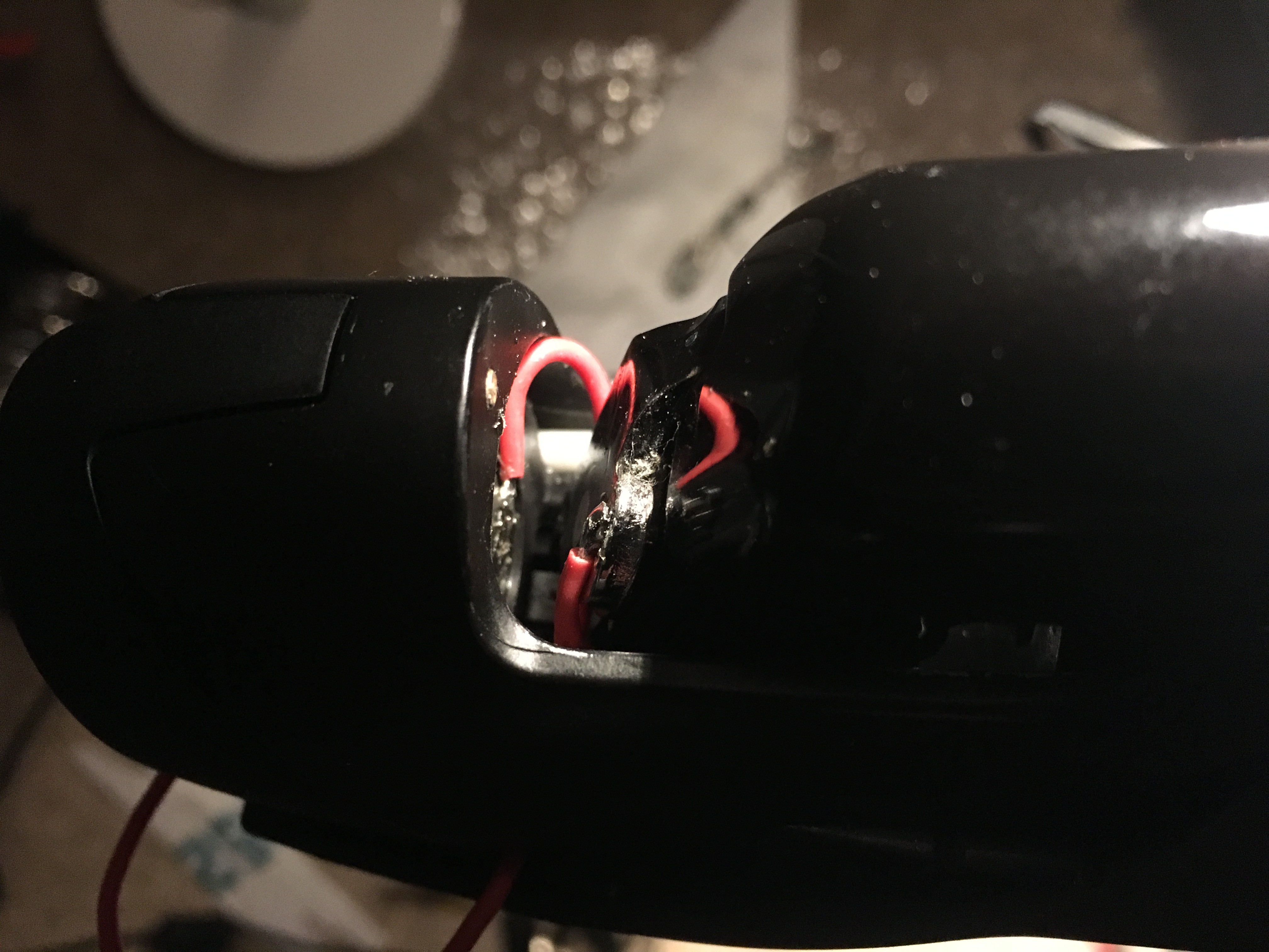
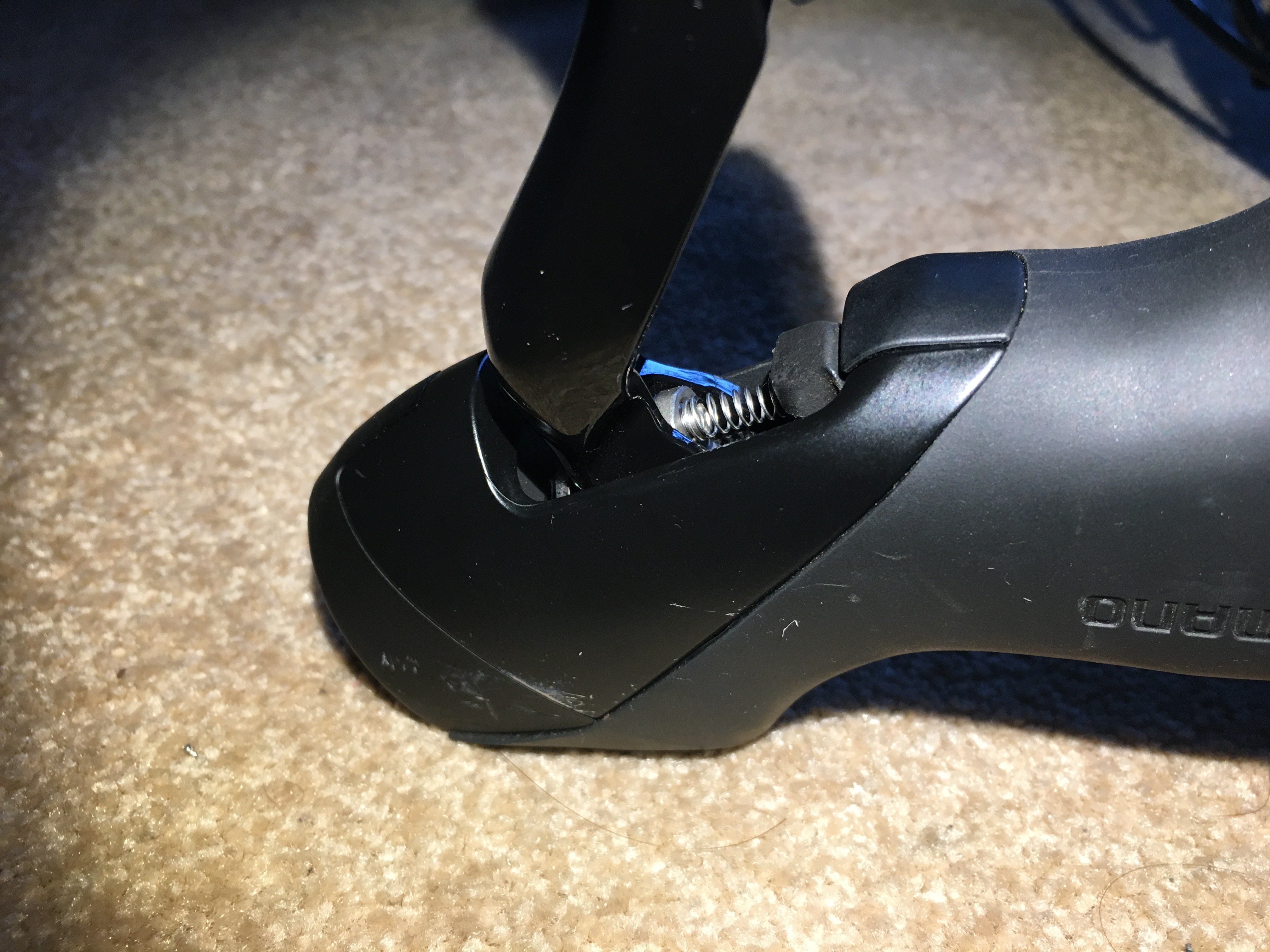
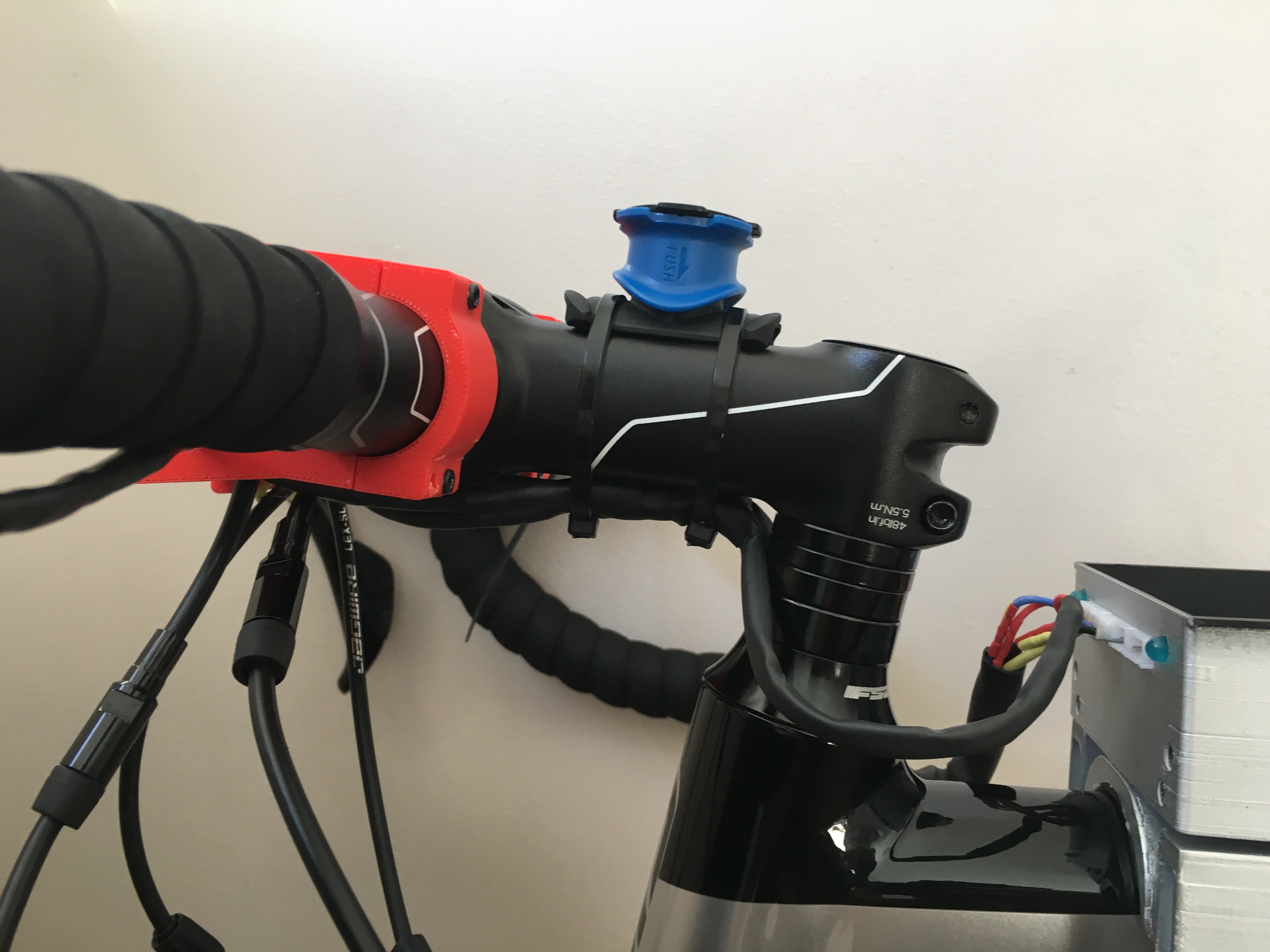
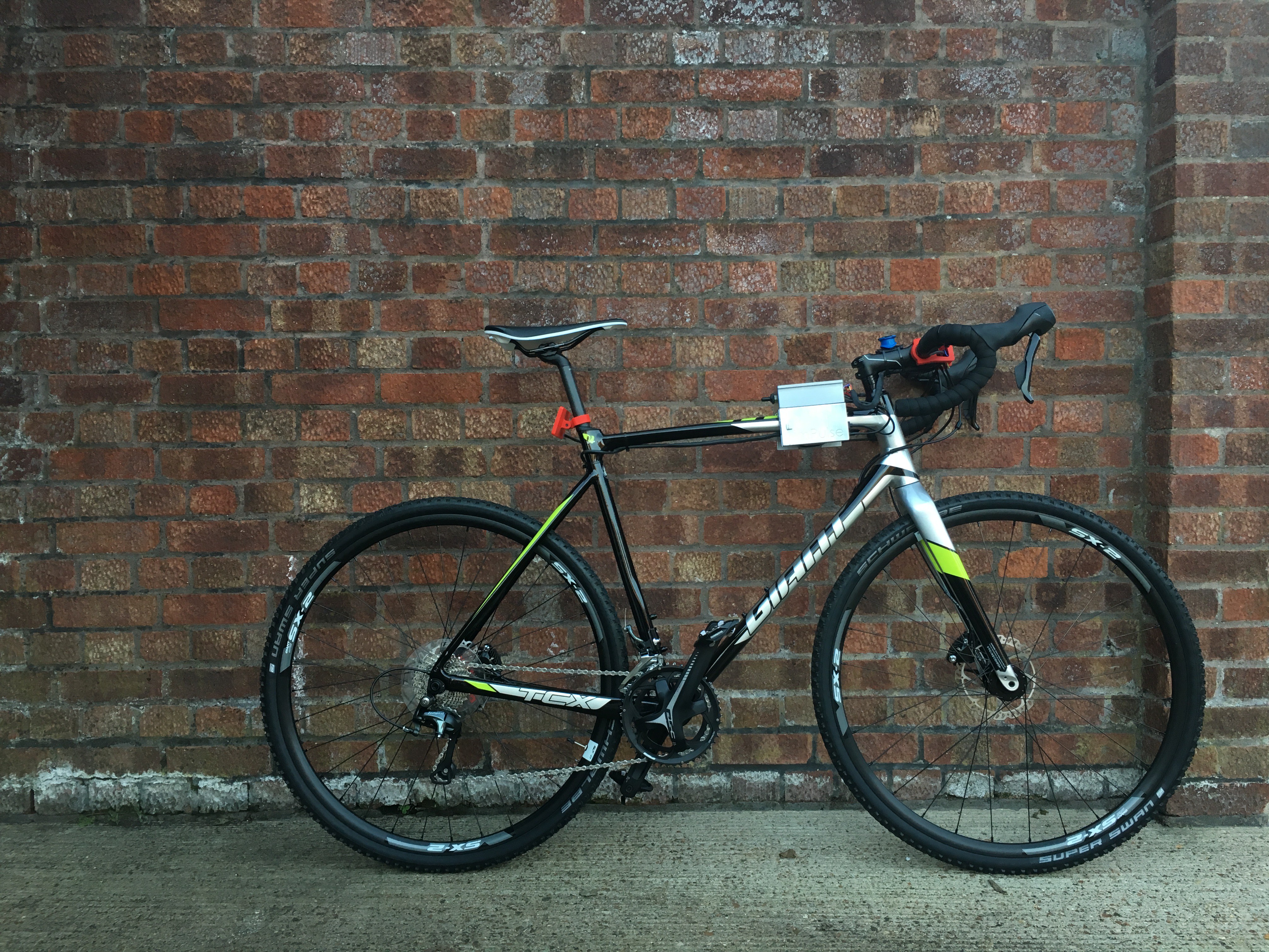
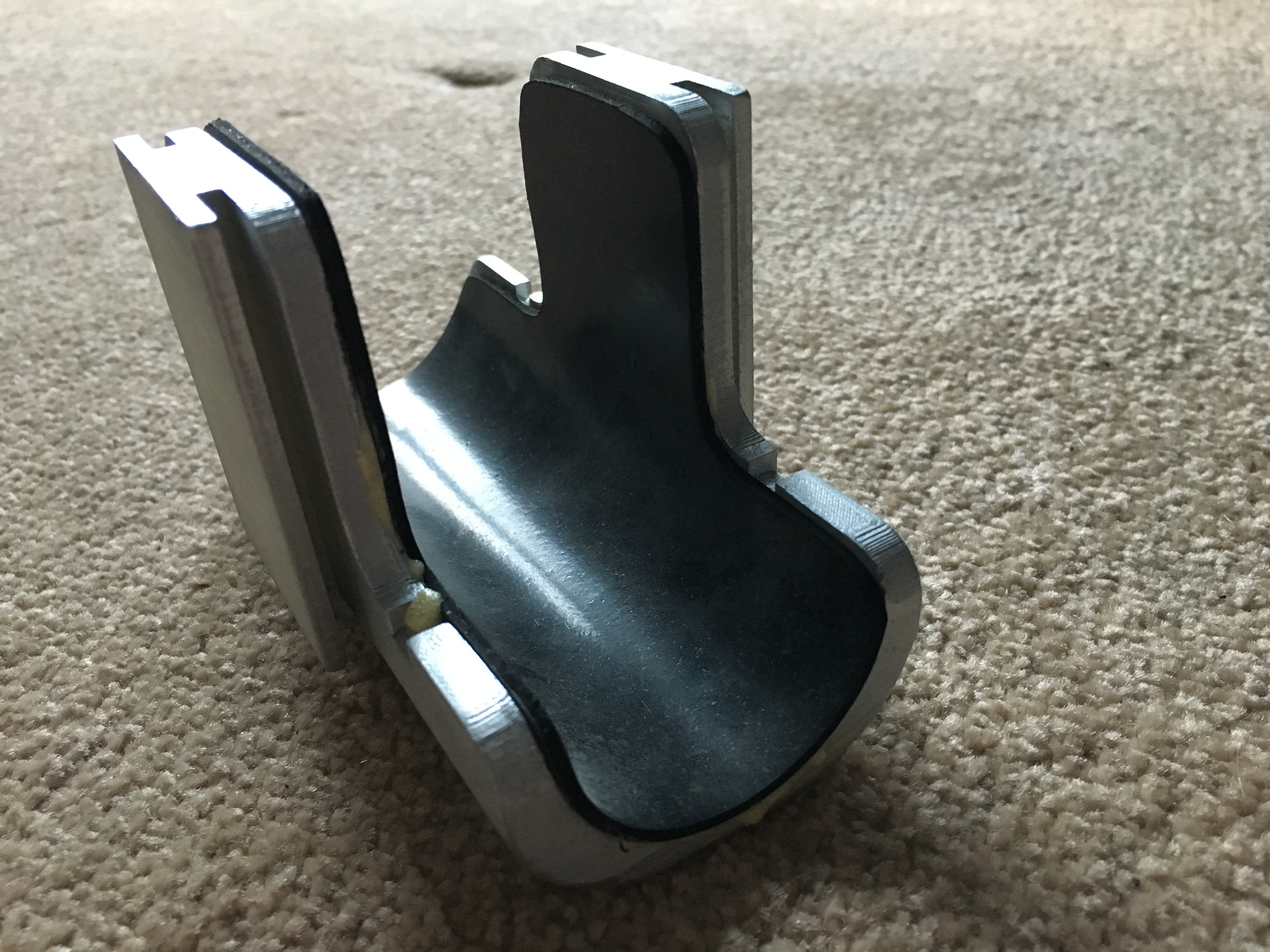
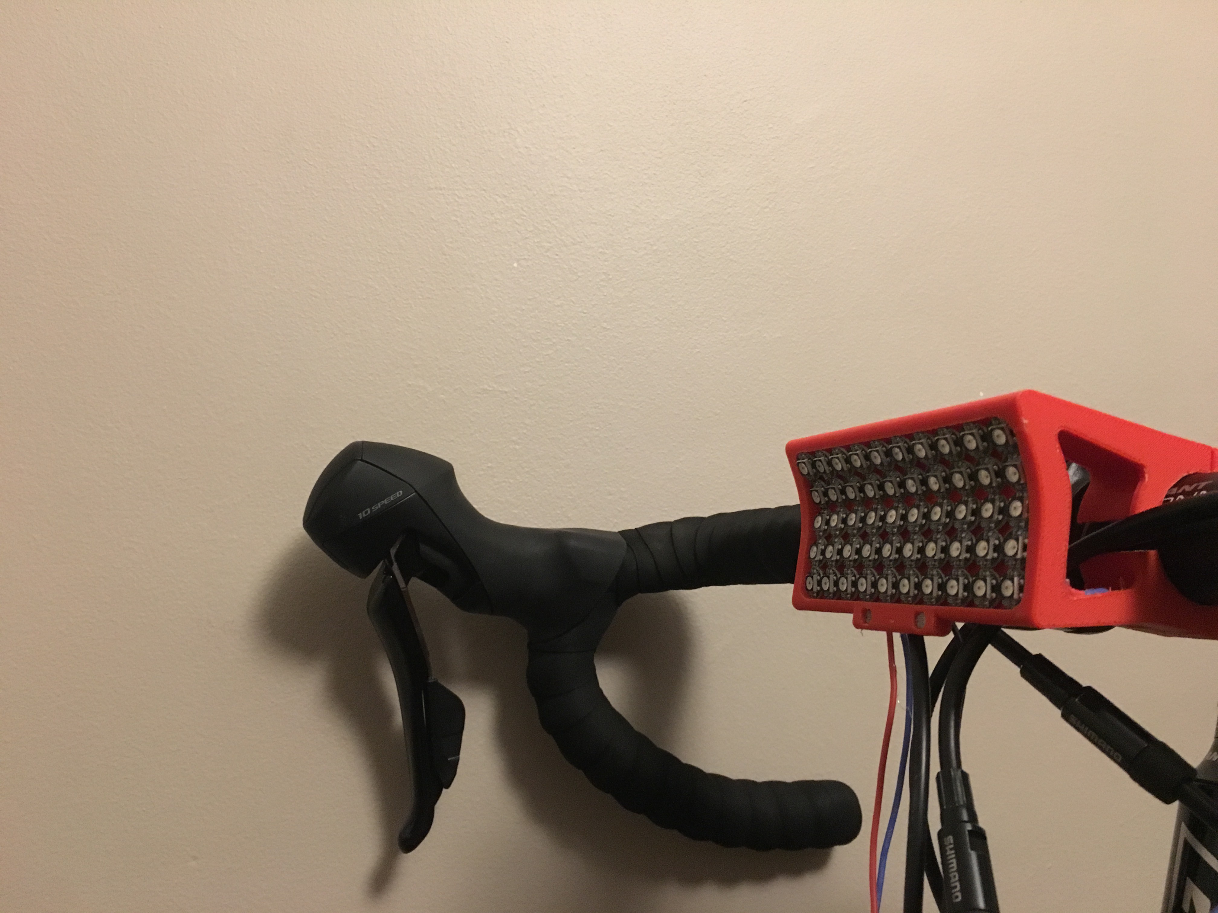
I am assuming that the headlight, rear light, motor and eBox are ready to be installed in your bike. Hence, the only thing to do is to 'convert' the braking levers so they can act as pushbuttons. I am trying to use a non-invasive methodology in order to implement the pushbutton effect in the braking levers.First thing I did was to spend a while trying to analyse the best way to attach cables and also if it possible to take advantage of conductive materials. My plan is the following:
- The braking light will be activated when the user pulls the braking lever. However, in my case there was a huge gap to cover. My solution was to use a spring as you can see in the pictures.
- The indicator will be activated when the user pushes the lever forward.
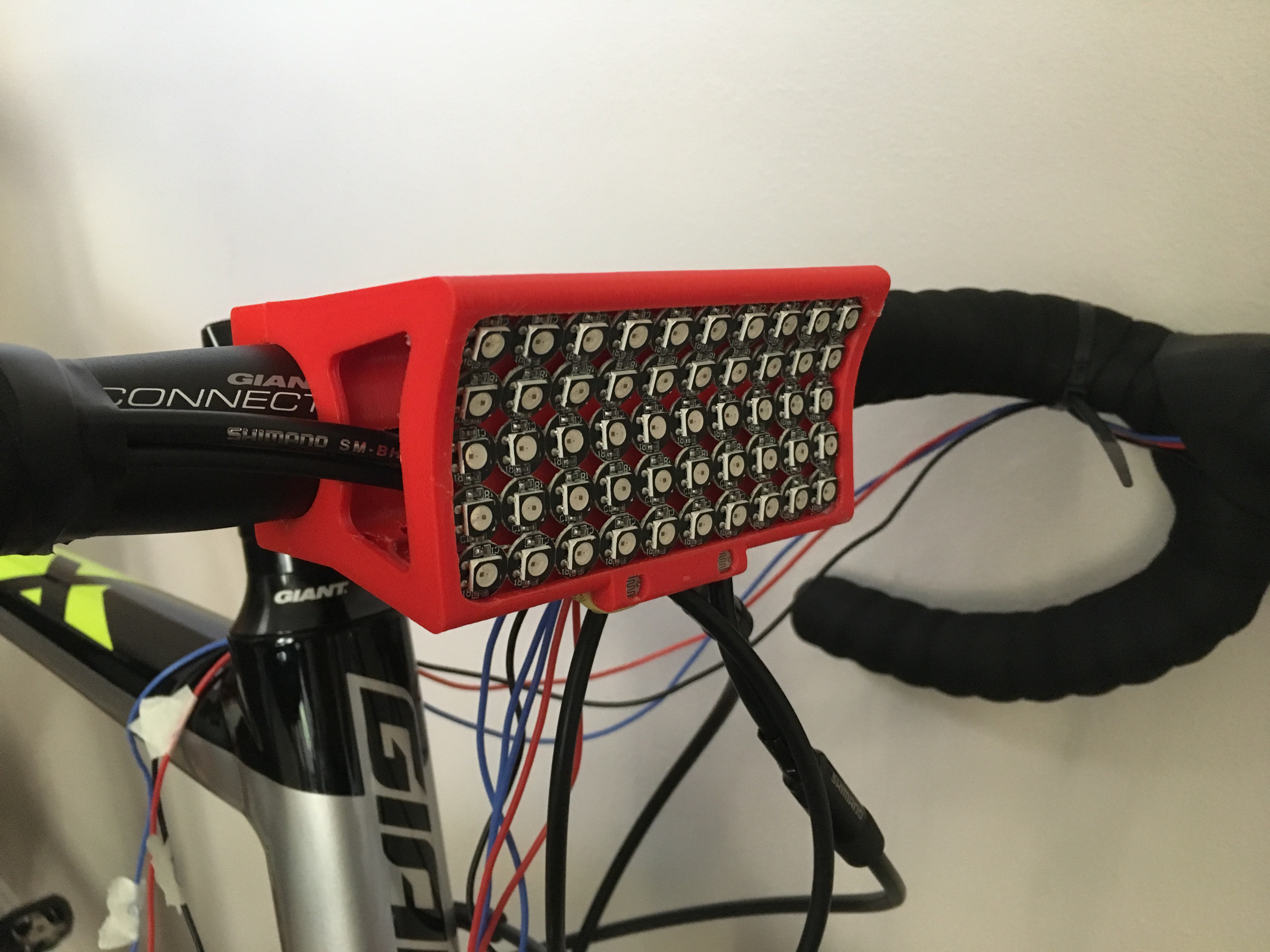
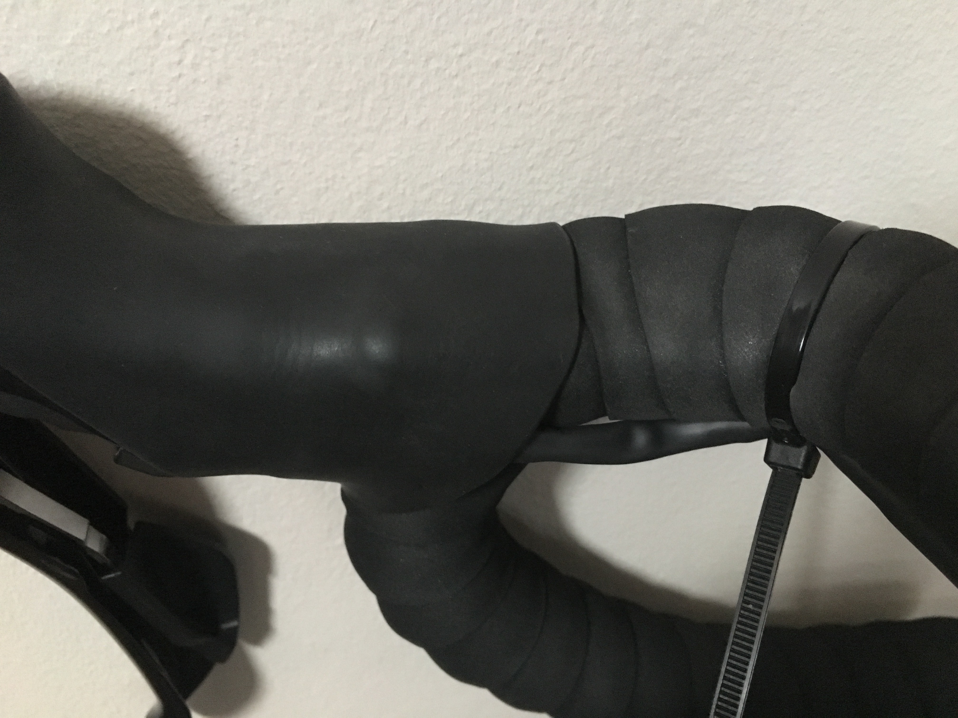
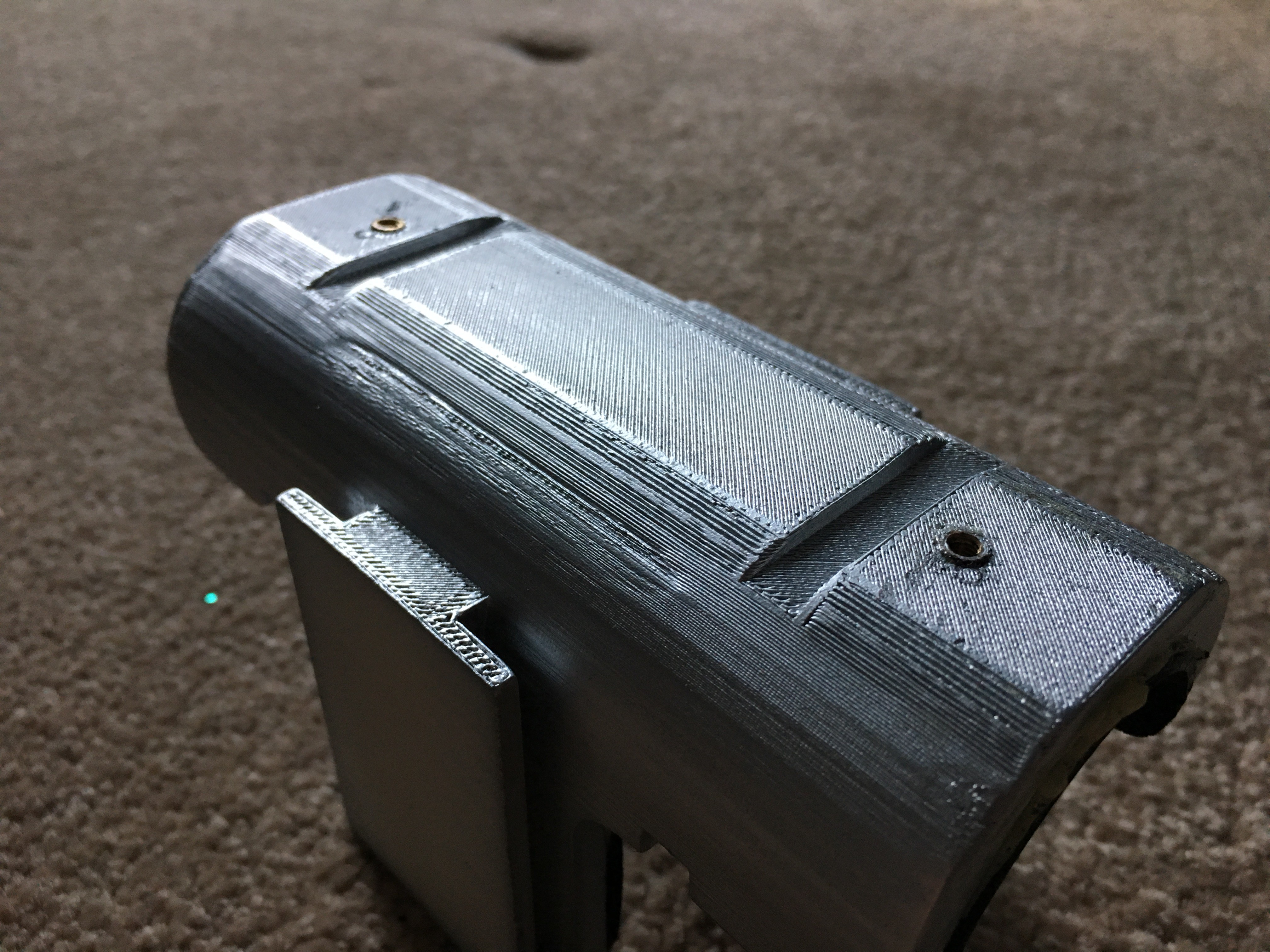
Now it is time for using your skills and decide which is the best way for routing all cables. I think the best way to explain it is to show some pictures (again).
UPDATE 21-10-18
After spending some time (a lot!) testing the hardware/ software stages of this project, I have to acknowledge that the tweaked levers worked amazingly well. Here is the final picture!
Q&A Section
Did you have use any invasive methodology (e.g. drilling) for the wiring?
No! The bike I am using was not precisely cheap, so I was forced to use non-invasive methods for the wiring. The main advantage is that you can remove anytime!
-
eBox Stage 2.0
10/06/2018 at 17:33 • 0 commentsI am back! Yes, it has been a while. I have been travelling for a conference and I have been preparing my presentation, some paperwork and finishing other projects. It was amazing!!
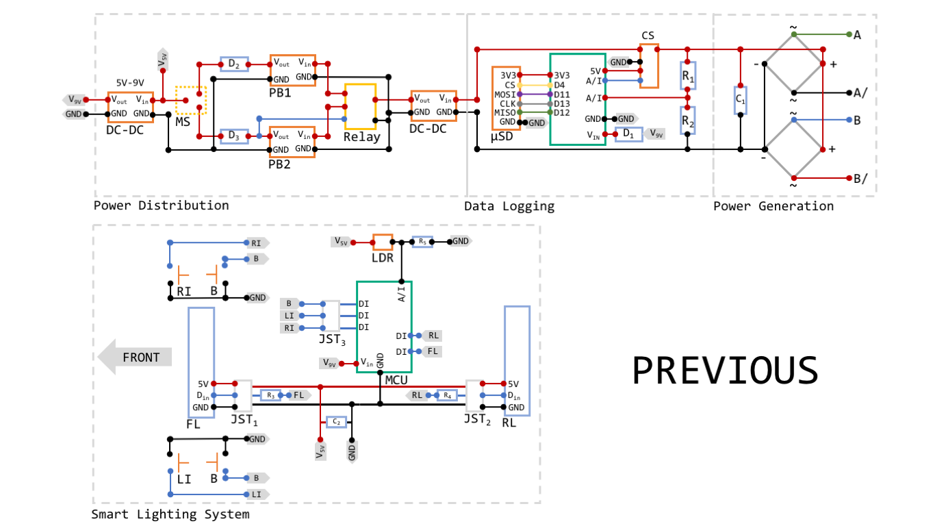
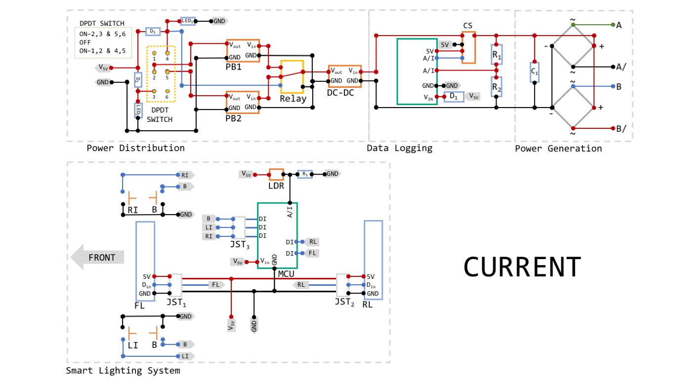
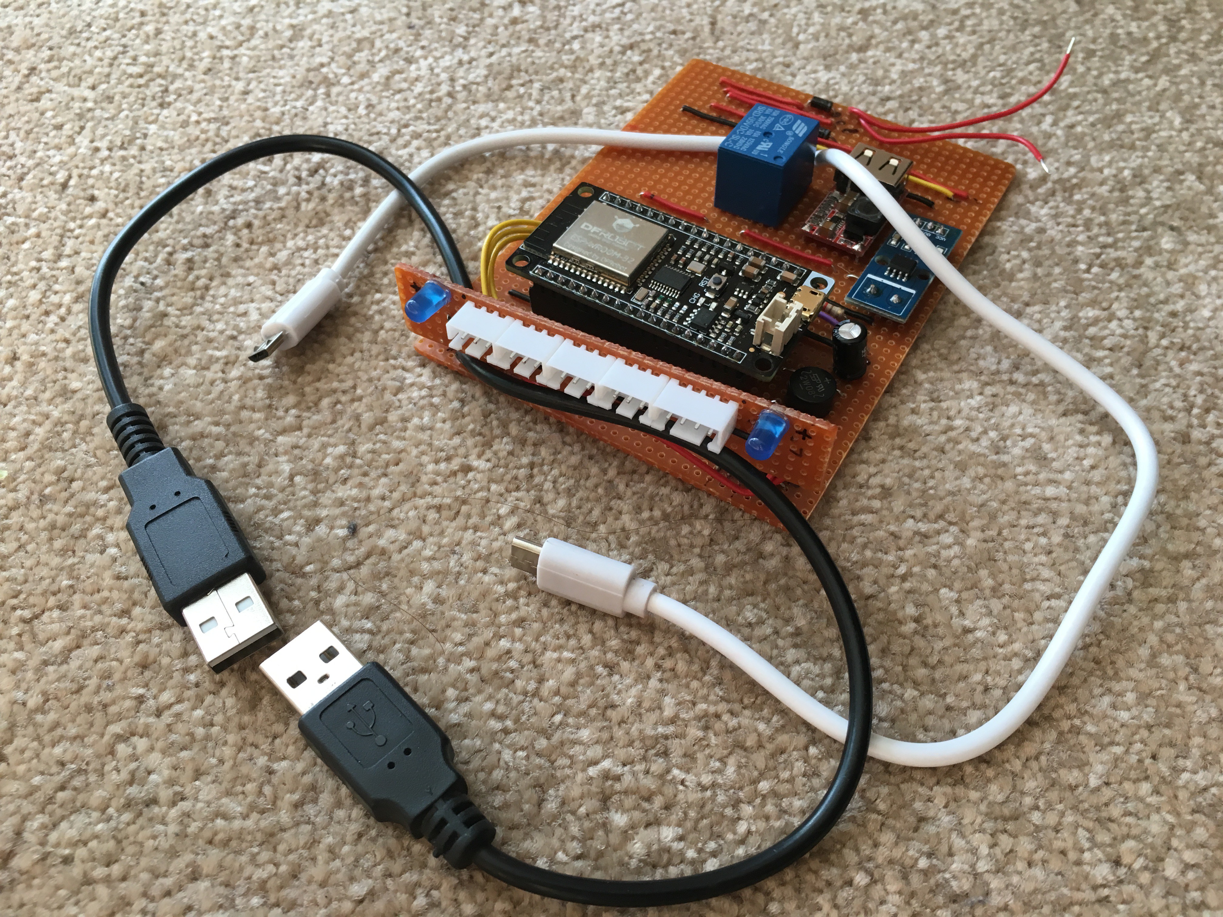
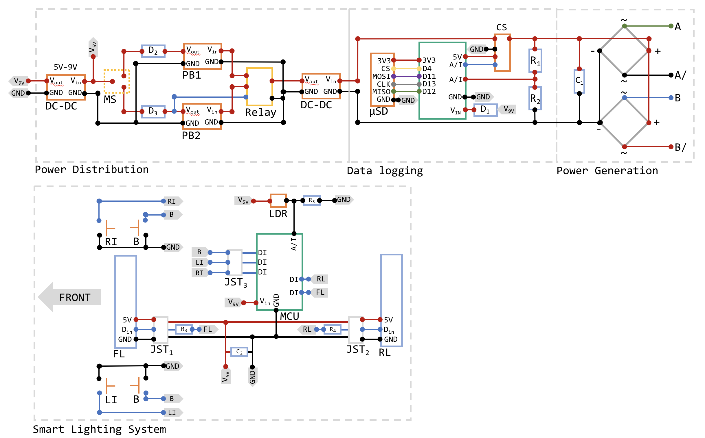
Coming back to the main subject, I know I did not explain much in the eBox Stage log entry, but it is mainly because I decided to upgrade the initial design. Both images are shown below, so both designs can be easily compared. Components needed for this stage are:
- 1 x 3D-printed eBox assembly
- 2 x 3D-printed Power Bank Housing
- 1 x 3D-printed eBox Mounting Bracket
- 1 x Strip Board
- 1 x Relay (SRD-05VDC-SL-C)
- 2 x Diodes (1N4007)
- 2 x USB 2.0 to Micro USB cable (1m)
- 2 x Power bank
- 1 x Single Solid Core (SSC) Black wire (0.6mmx1m)
- 1 x SSC Red wire (0.6mmx1m)
- 1 x SSC Green wire (0.6mmx1m)
- 1 x SSC Yellow wire (0.6mmx1m)
- 1 x SSC Orange wire (0.6mmx1m)
- 1 x SSC Purple wire (0.6mmx1m)
- 2 x M3 screw
- 1 x Rubber Sheet (250x250x1.5mm)
- 2 x M3 Threaded brass insert
- 8 x Neodynium Magnet Disc (3x20mm)
- 1 x Stainless Steel Rod Bar (200x2mm)
- 2 x Blue LED
- 2 x 220Ohm Resistor
- 1 x DPDT Switch
![]()
![]()
Please find all changes listed below:
- FireBeetle (ESP32) instead of Arduino Nano v3
- 5V to 9V DC converter is removed
- C2, R3 and R4 are removed
- There was a bug in the relay connection that keeps the coil active permanently. With a Double Position Double Throw (DPDT) switch, this problem is solved.
- LED1 and LED2 have been added, so the user can see which power bank is being used to provide energy to the system
The addition of the ESP32 brings some advantages to the system:
- An improved processor - there is no need of using two MCUs
- BLE connectivity - the uSD module is removed and now all data is directly streamed to your phone
- OTA (Over The Air) updates
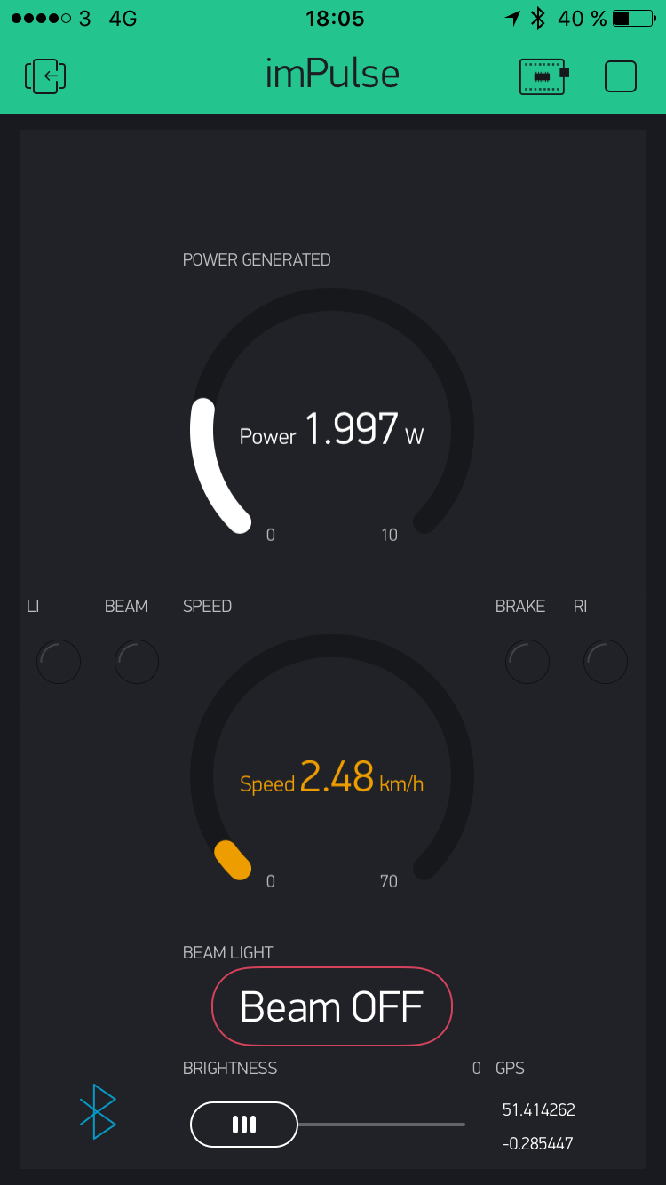
- Blynk App is used while you ride like a dashboard, where different commands can be executed, the generated power is directly shown and the linear speed is acquired from your phone GPS and displayed too. (You will be able to download and modify my program, so anything is possible!)
- There is no need of installing a DC-DC step-up converter. Everything works within 5V.
As a remainder, I would like to clarify abbreviations shown in previous pictures:
- D stands for 'Diode'. Diodes used are 1N4007
- R stands for 'Resistor'. R1 is 1KOhm, R2 is 120Ohm and R5 is 10KOhm
- FL stands for 'Front Light'
- RL stands for 'Rear Light'
- RI stands for 'Right Indicator'
- LI stands for 'Left Indicator'
- B stands for 'Brake'
- The relay used is a SRD-05VDC-SL-C
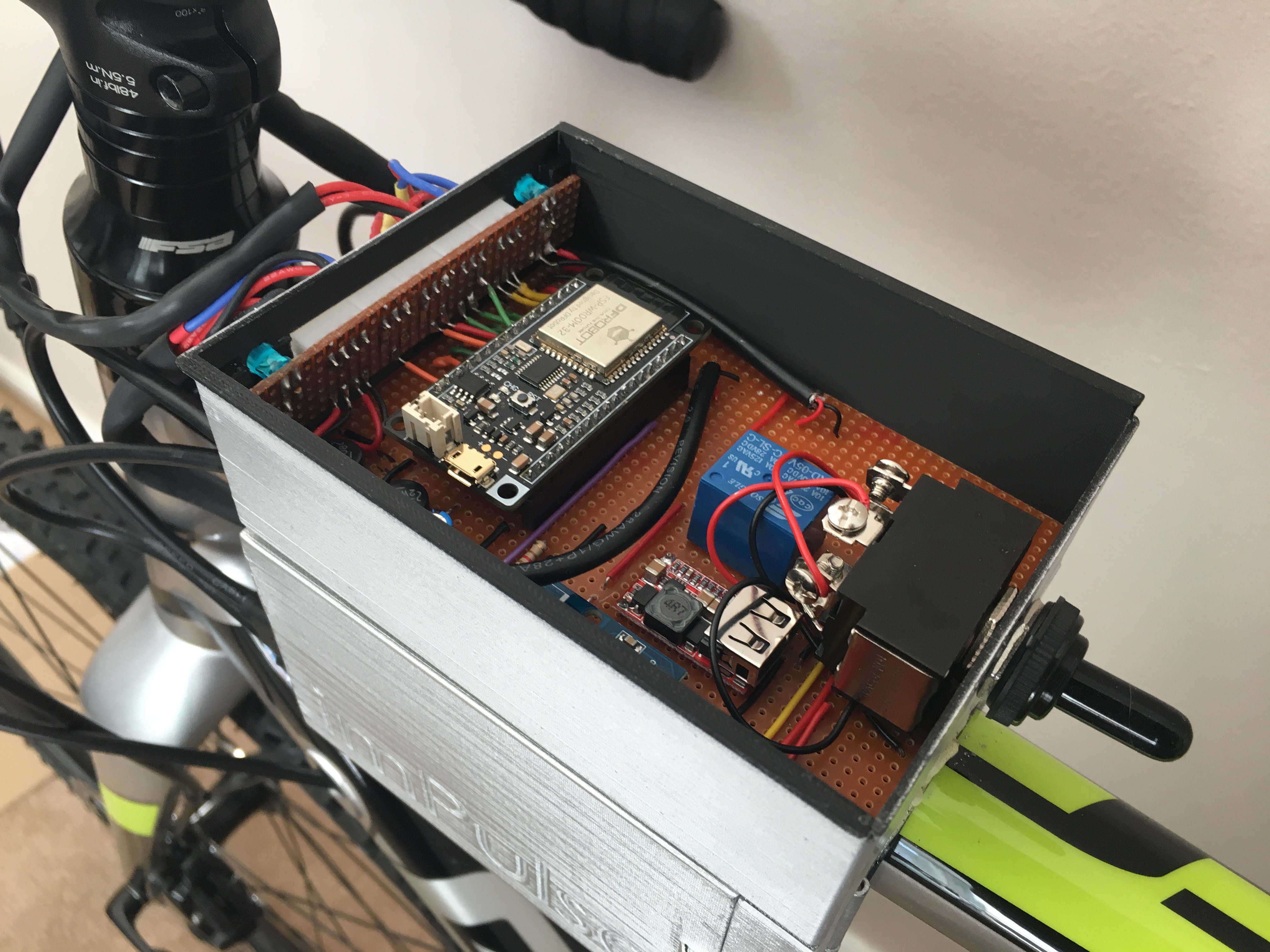
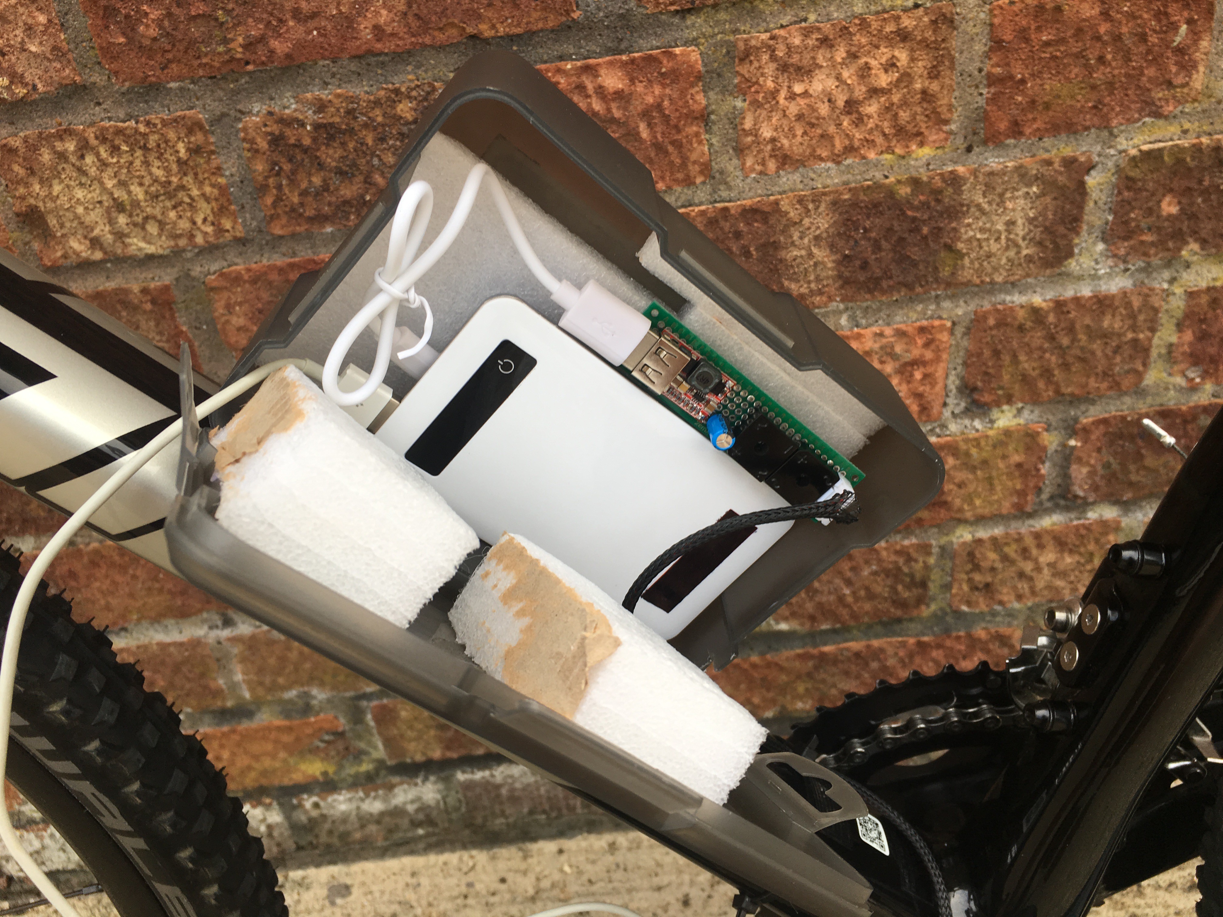
And....real pictures!!![]()
I also have to say thatI am looking for hardware bugs as everything seems to be perfect in the diagram (like the relay bug).
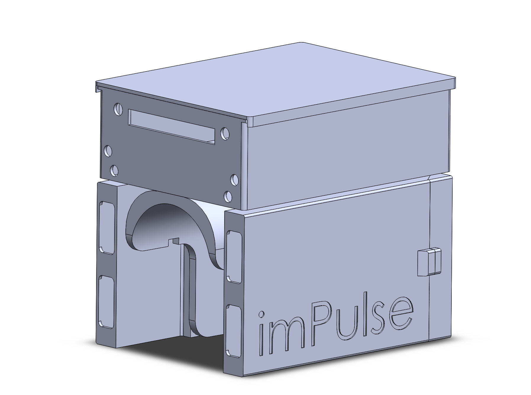
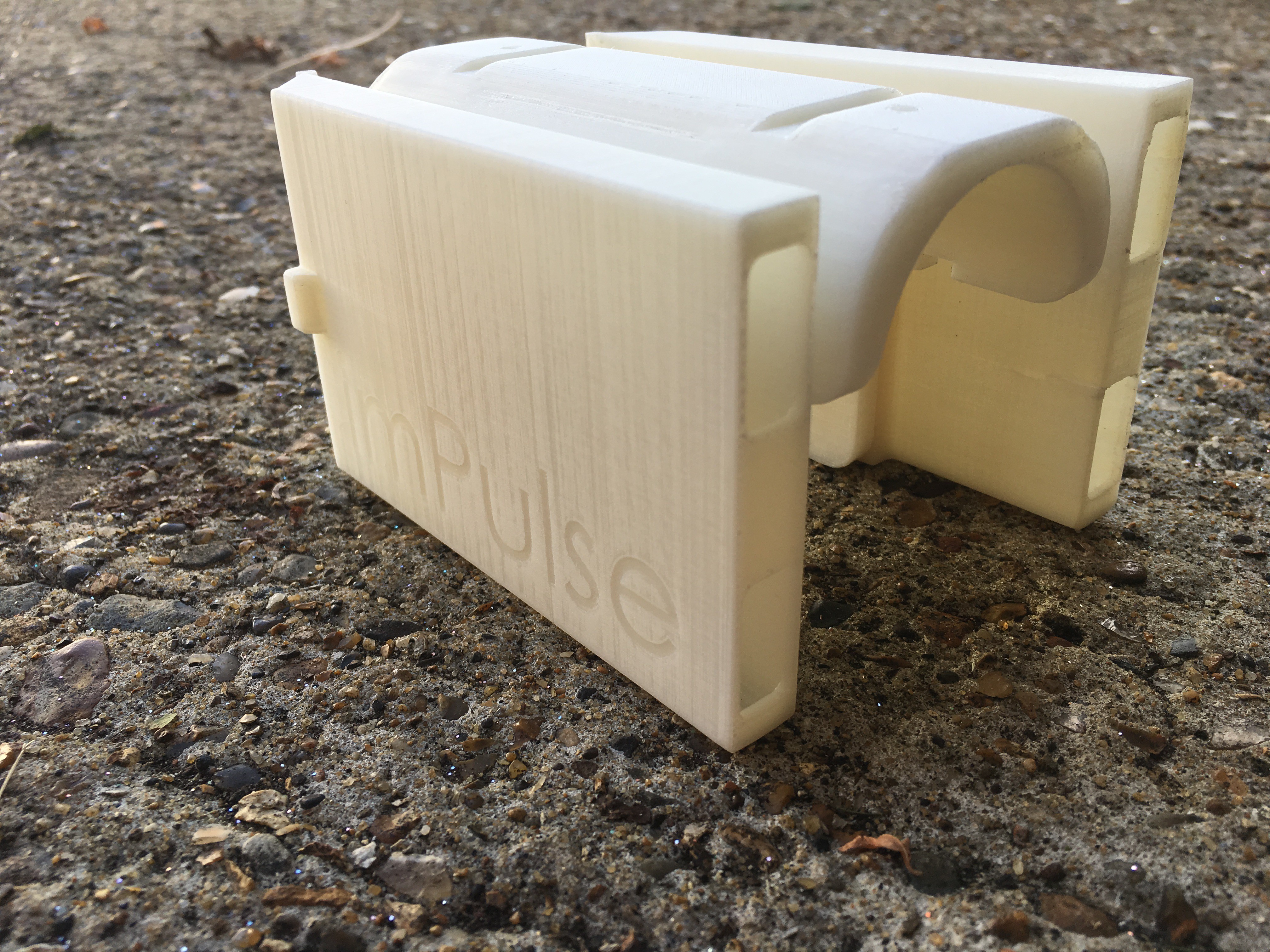
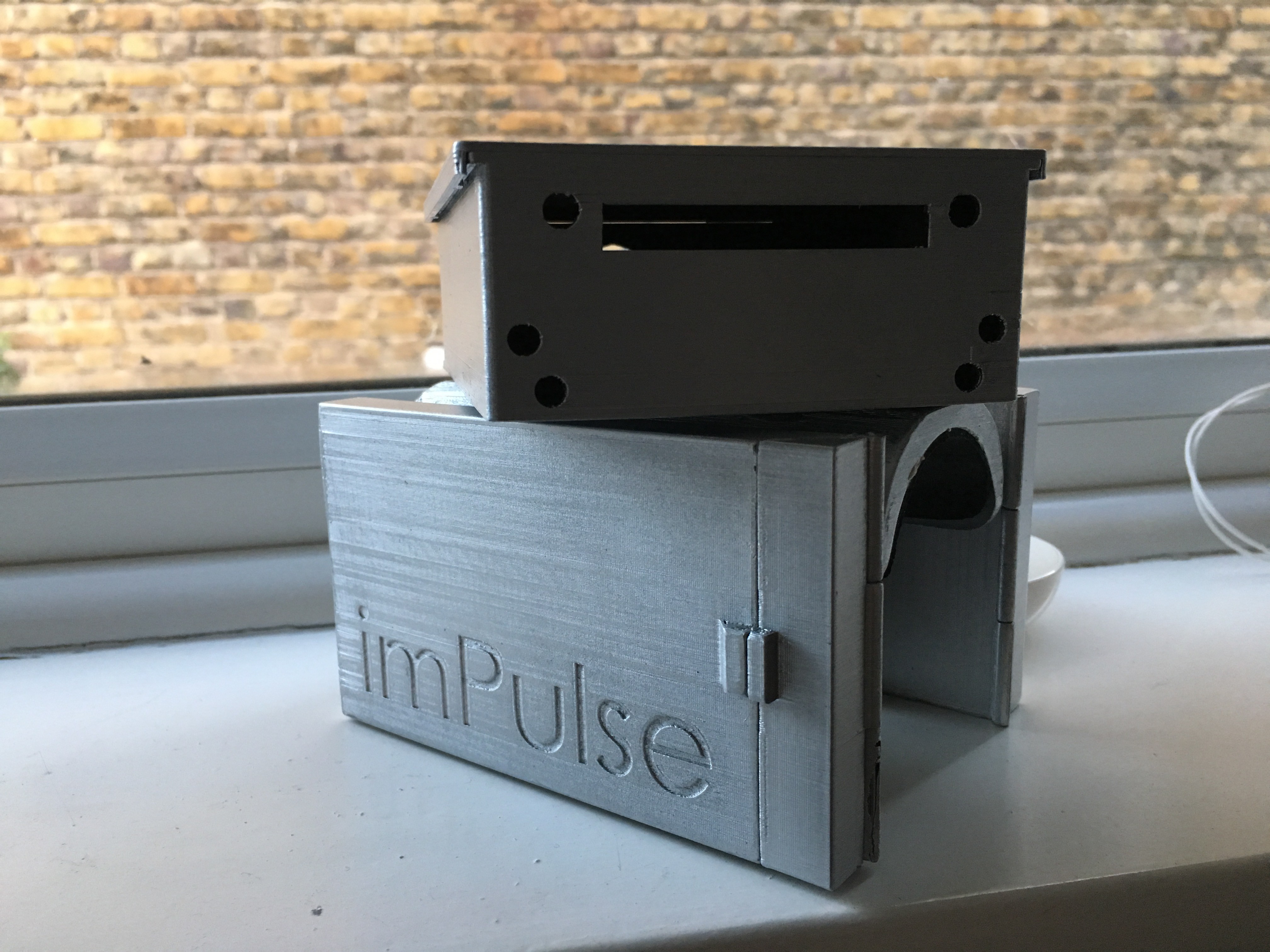
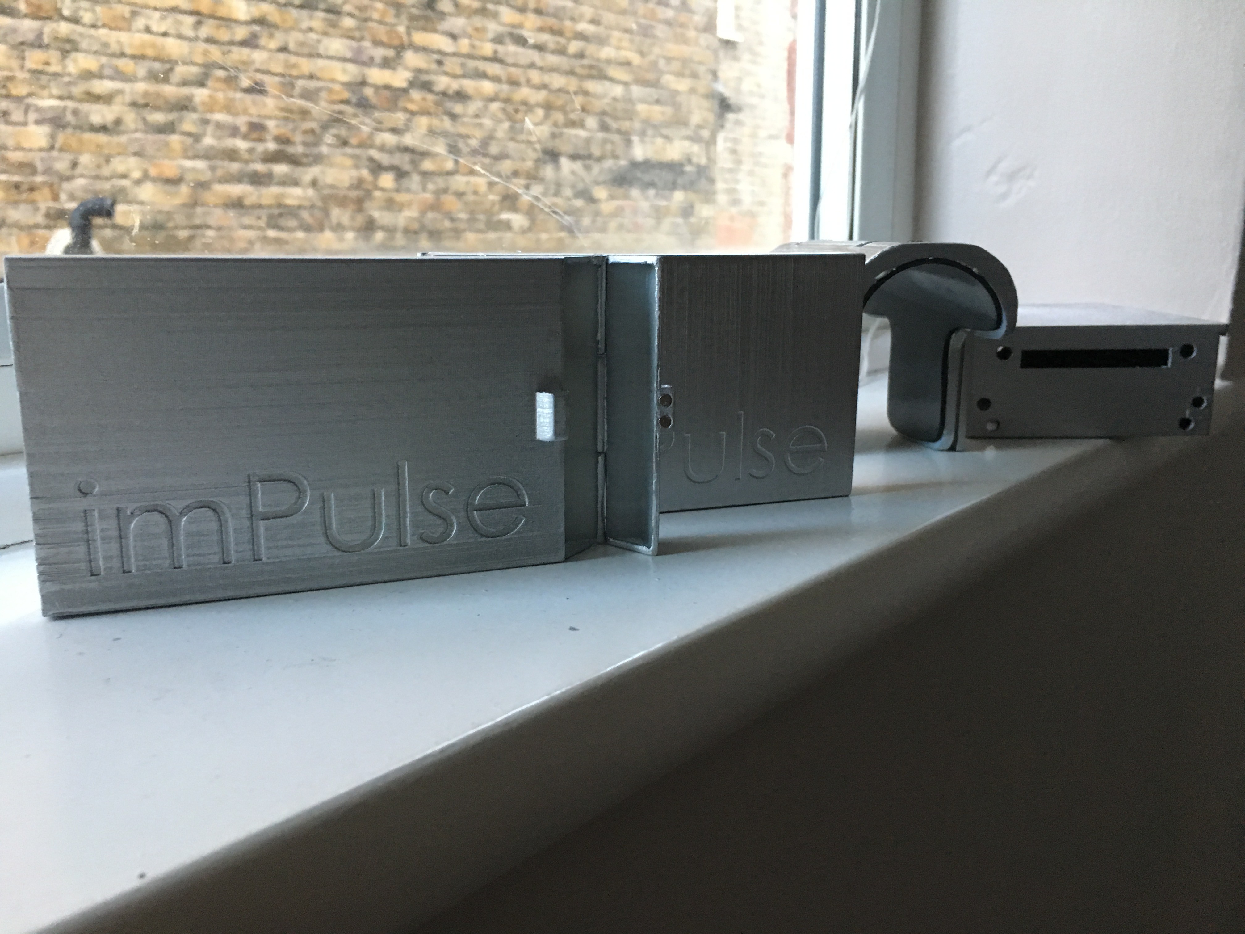
Regarding the eBox design, I mentioned that I wanted to leave the bottle cage mounting point for its purpose and I managed to do it. Below you will find the CAD (models uploaded asap) of the assembly which has four components and is modular:
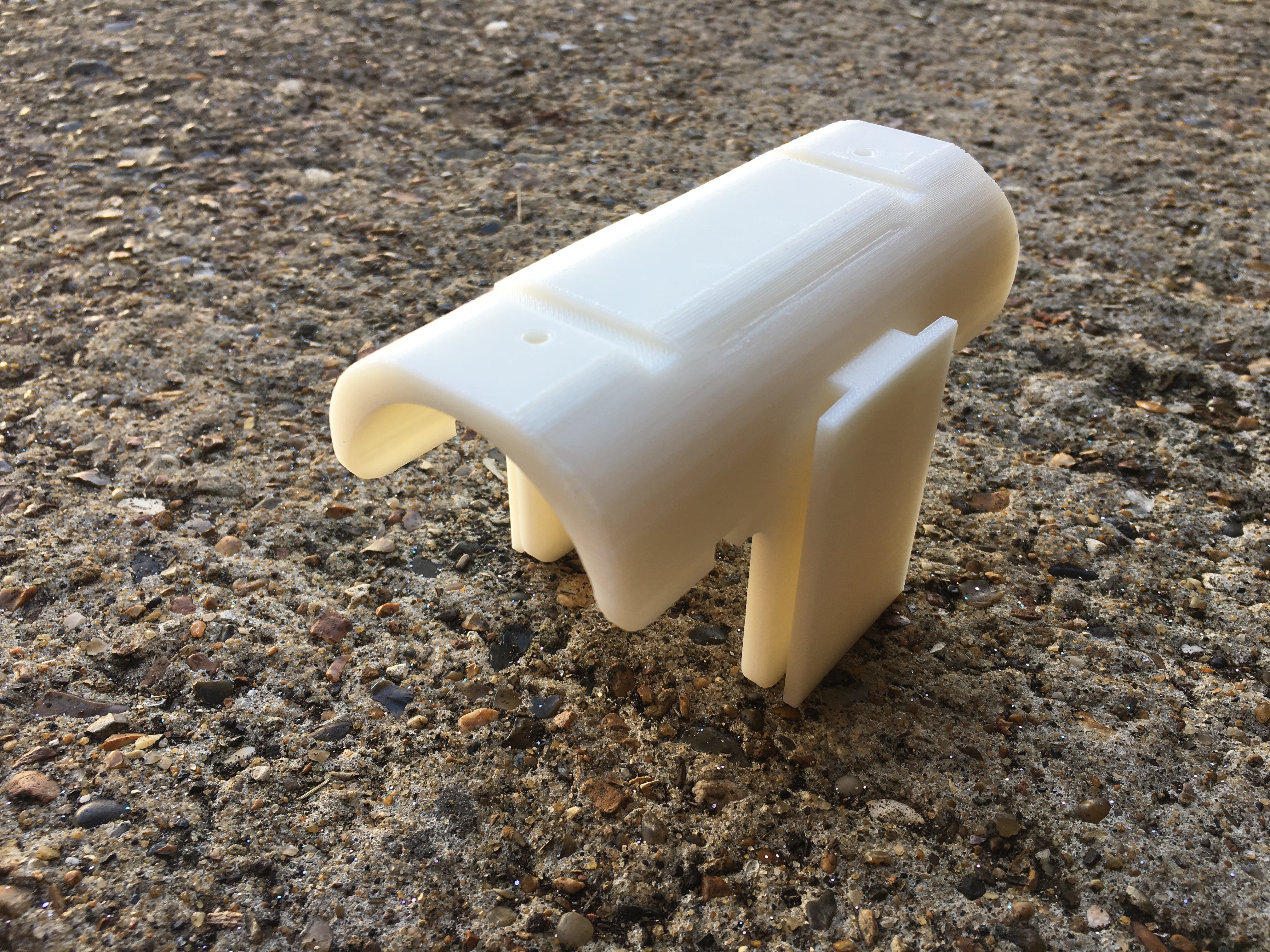
- An adaptor for the bike main frame that holds all parts together and makes the system just one part that can be easily removed for cleaning purposes. This is the only part that changes depending on your bike and is located right after the steering wheel keeping other mounting points free!
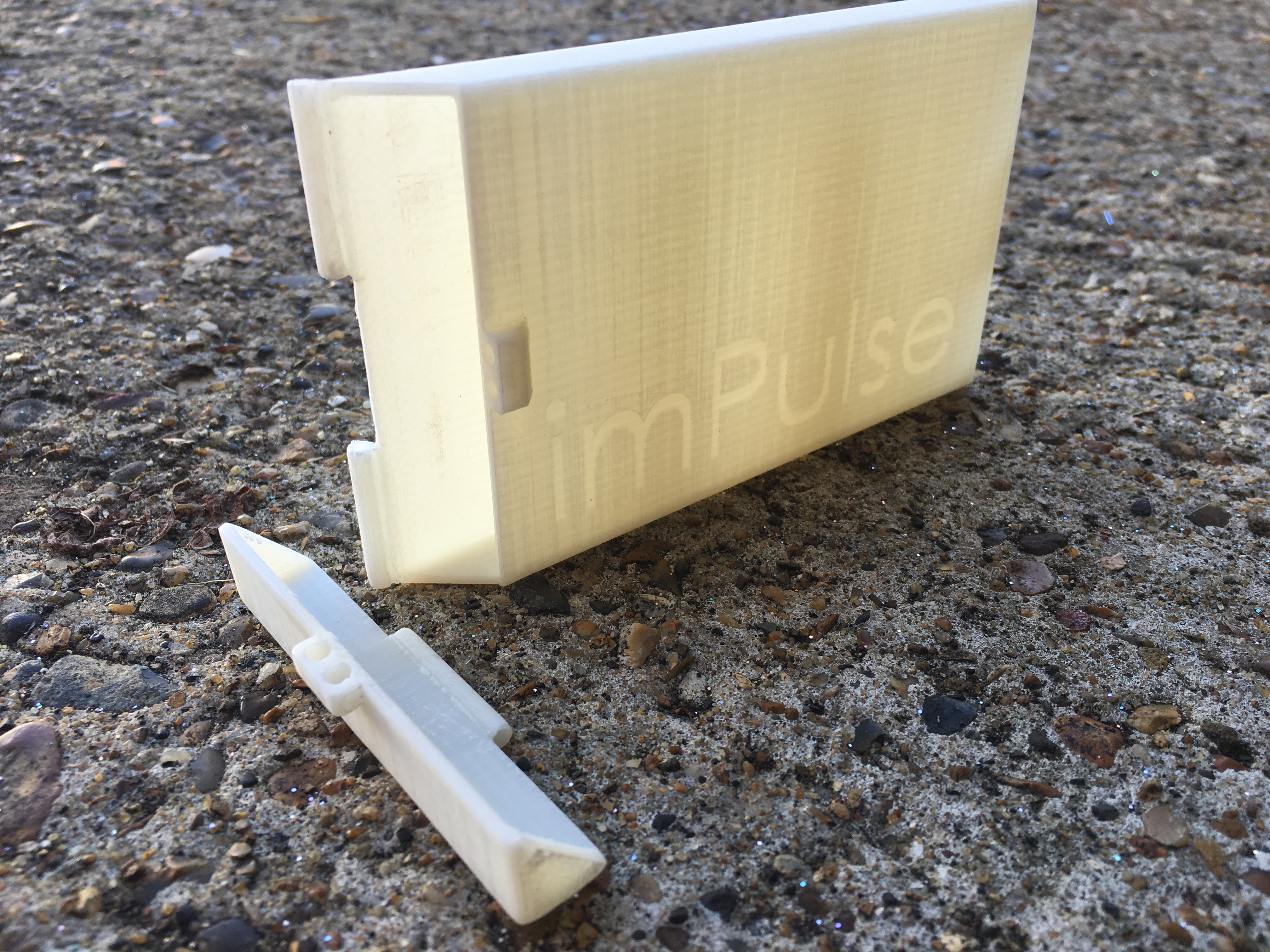
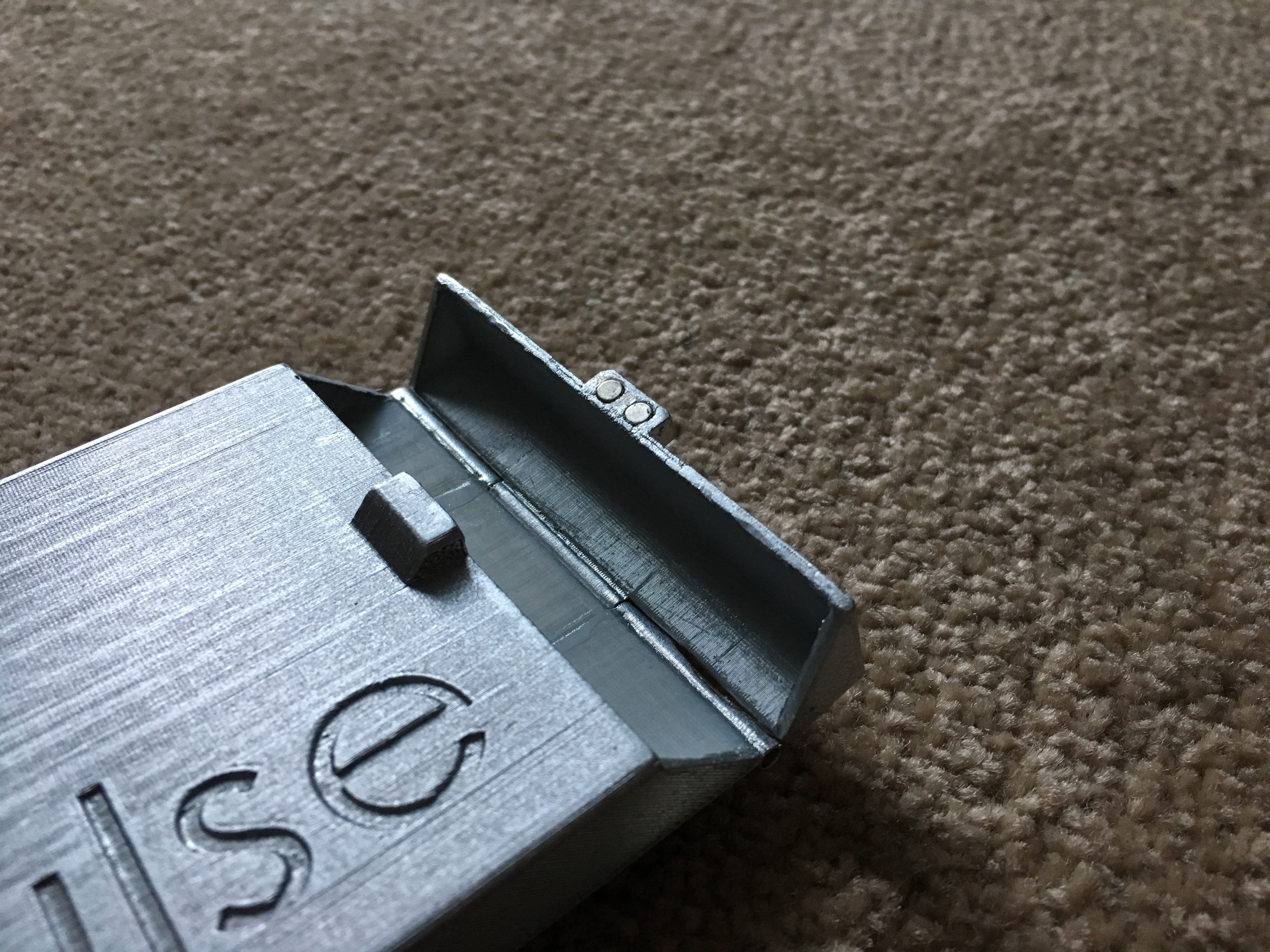
- Two power bank containers - you can also decide if you prefer to charge your phone instead! It only needs to have a T-slot, so give wings to your imagination! This containers can be opened/closed at any time as they have a magnetic mechanism (I really like magnetism!)
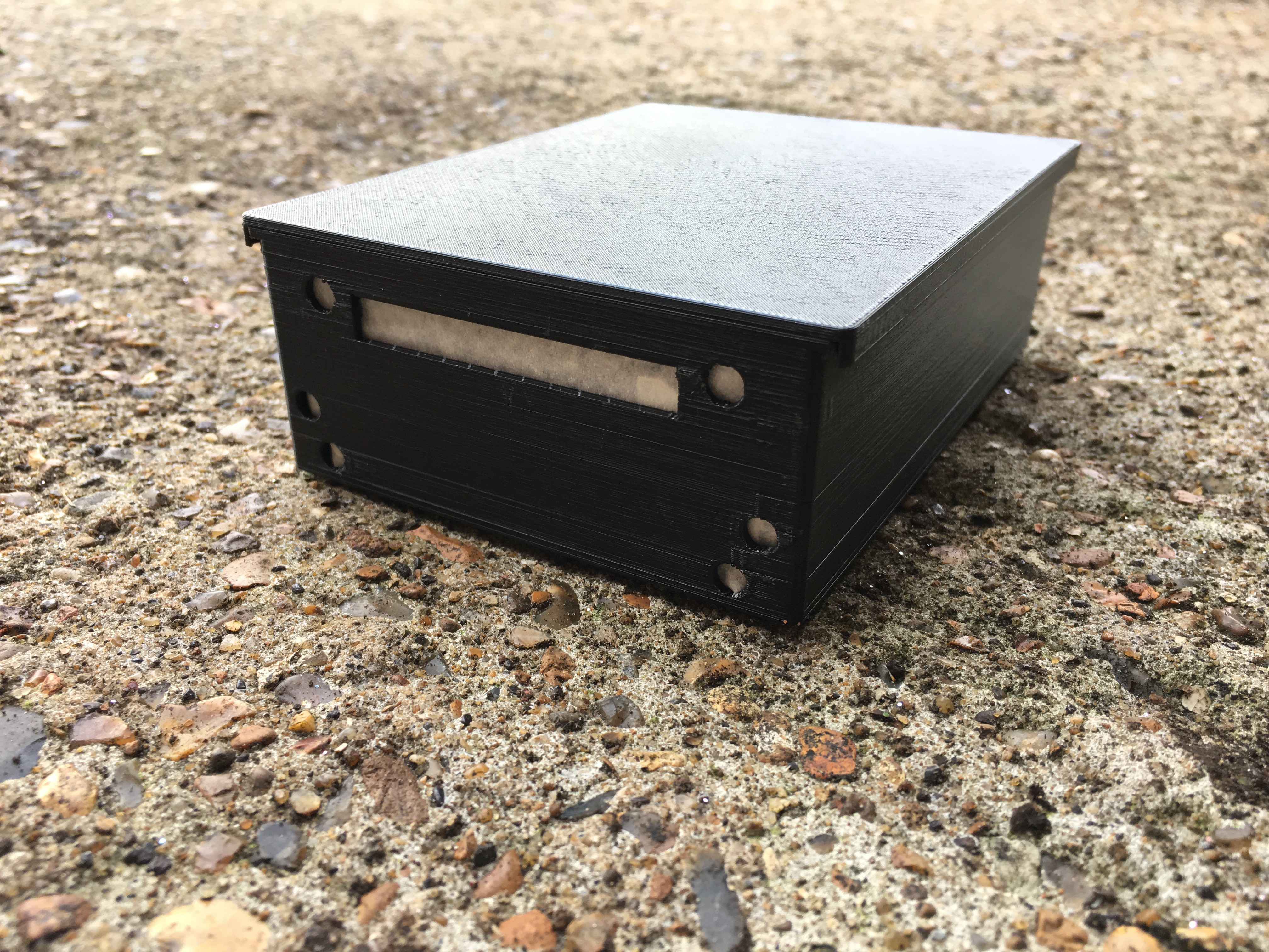
- The bECU (eBox) is fixed using screws on top of the adaptor.
Unfortunately, due to the time being I could not design a waterproof system, but I have it in mind for future releases! Now, let's jump to the real world again:
UPDATE - 18/10/18
And here they are! I also glued a rubber sheet and added the M3 inserts to the eBox mounting bracket. Hinges and magnets were also added to the power bank housing. It looks nice, isn't it?!
Q&A Section
Is it possible to make a reduced-size circuit?
I am sure it is possible. What I am doing is very simple and I am planning to design a proper PCB that I am sure that will be more compact.
How does the power bank charge and discharge sequence work?
This a good one because it affects the whole system design. The charging state has priority over the discharging, so the system was designed having this little but crucial aspect in mind.
-
Data Logger Stage 2.0
08/18/2018 at 19:14 • 0 commentsYes, I am also upgrading the Data Logger Stage. This is the last entry for this challenge as it involves all hardware/software debugging. These to parts are merged to create a unity, a system!
I am changing some of the components. To be honest with you, a physical data logger was very interesting to star with, but we are in the IoT era! Hence, here is the components list for this stage:
- 1 x FireBeetle (ESP32)
- 1 x Current sensor (ACS712-30A)
- 1 x 1 kOhm resistor
- 1 x 120 Ohm resistor
- Blynk app installed in your phone!
You can use all documentation available on my previous logs to create the voltage divider and to calibrate the current sensor. I will comment here all changes needed in order to transfer your code from a conventional Arduino (or similar) to the ESP32.
Hardware changes
The ESP32 has very nonlinear ADCs (Analogue to Digital Converter) despite of a greater resolution (12-bit or 4096 div). I had a very big headache trying to get reliable readings until I realised that the ADC was not working like the Arduino one. I measure the maximum voltage allowed for analog measuring and was 3.14V, not 3.3V. I would recommend you to read the Espressif ADC documentation (just in case).
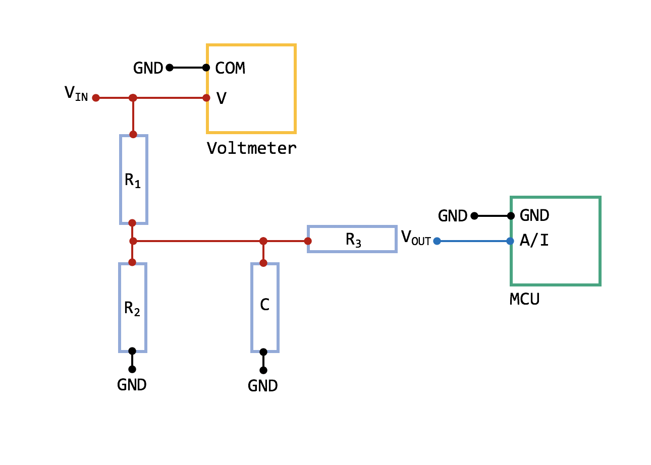
My test circuit was just a voltage divider, but I added two extra components, a first-order-filter and multiple sampling (image below):
![]()
Here are the input parameters:
- Vin -
- Vout -
- R1 - 1KOhm
- R2 -
- R3 - 10 KOhm
- C - 10nF
After these changes, readings were very stable, so I defined a "true voltage" calibration function and also implemented it in the code. The spreadsheet can be downloaded from GitHub. I have to point out that voltages below 0.114V were not considered by the ADC.
The current sensor requires 4.5 - 5.5V. My power banks were providing 5.016V but only around 4.3V were provided to the sensor as I had a diode for the DPDT (diagram here). The sensor worked just fine, but the reading from the module MUST go through the calibration function first (to avoid any painful headache).
Another thing I had to change in the hardware was the addition of voltage dividers for the LDRs readings. Unfortunately, I had them connected directly with the lights, so the voltage supplied was 5V instead of 3.3V.
Software changes
First of all, I planned to incorporate Blynk on my setup, so the bike rider will experience something similar to a car dashboard. Here is my dashboard setup:
I wanted to have:
- The power generated transmitted through BLE (Bluetooth Low Energy)
- The linear speed retrieved from the phone GPS sensor.
- LEDs to show that indicators, break light and beam light are ON/OFF
- The chance to switch ON/OFF the beam light manually any time and adjust the brightness.
Anything is possible with this app and your imagination. I encourage you to build something completely different and at your own choice, something that only you will find useful. That is why I chose Blynk!
After testing most of the codes regarding Blynk, sensors and light system separately, I finally created a unique file: imPulseMain. I had several issues with the ESP32 and now I understand why it is categorised as a developing board. No worries, all of them are listed in the code:
- FastLED library was not working properly until #define FASTLED_ALLOW_INTERRUPTS 0 was declared. I almost give up on this until I found the issue here.
- Interrupts are defined in a different way. This post was very useful.
- D2 and D3 in the ESP32 used in conjunction with interrupts is a VERY BAD idea. The interrupt count went crazy when D2 was enabled and the board was not able to reset (RST) when D3 was used.
- Some of the D/O (Digital Output) cannot send a LOW signal. It does not matter what you do.
However, the good news are that I managed to make everything work. Still minor bugs but will be fixed in future releases in conjunction with software upgrades:
- PID controller for LDRs
- Addition of the other two LDRs
- Startup protocols
- Hardware diagnosis
Now, the final video!
-
Power Generation Stage 2.0
08/18/2018 at 19:13 • 0 commentsAs this log entry says, I am now upgrading the current power generation setup. Please find below the goals for this stage:
- Aluminium pinion and spur gear manufacturing.
- Aluminium motor bracket.
- Explained power generation circuit.
So, why Aluminium everywhere? Let me show you a picture:
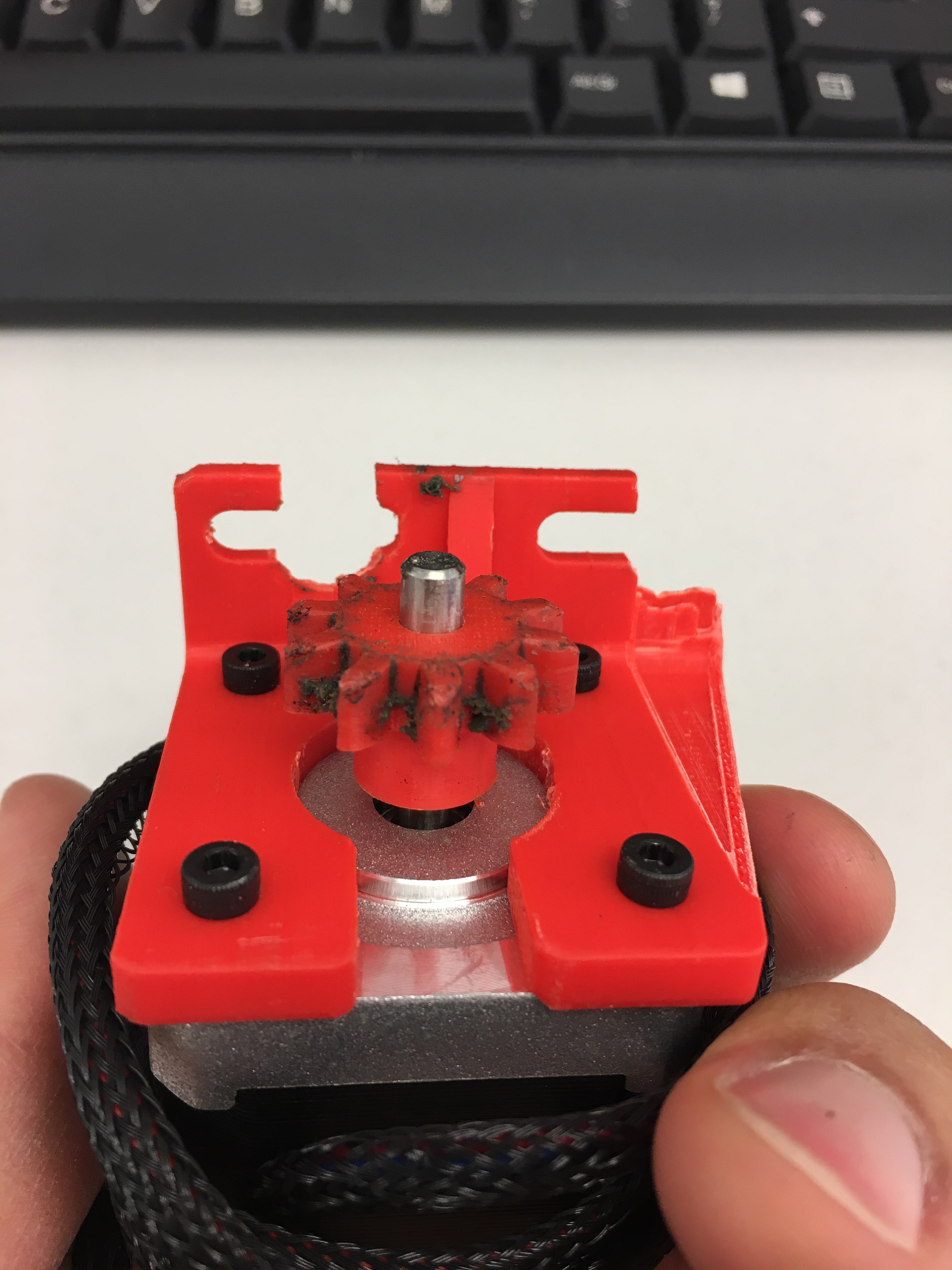
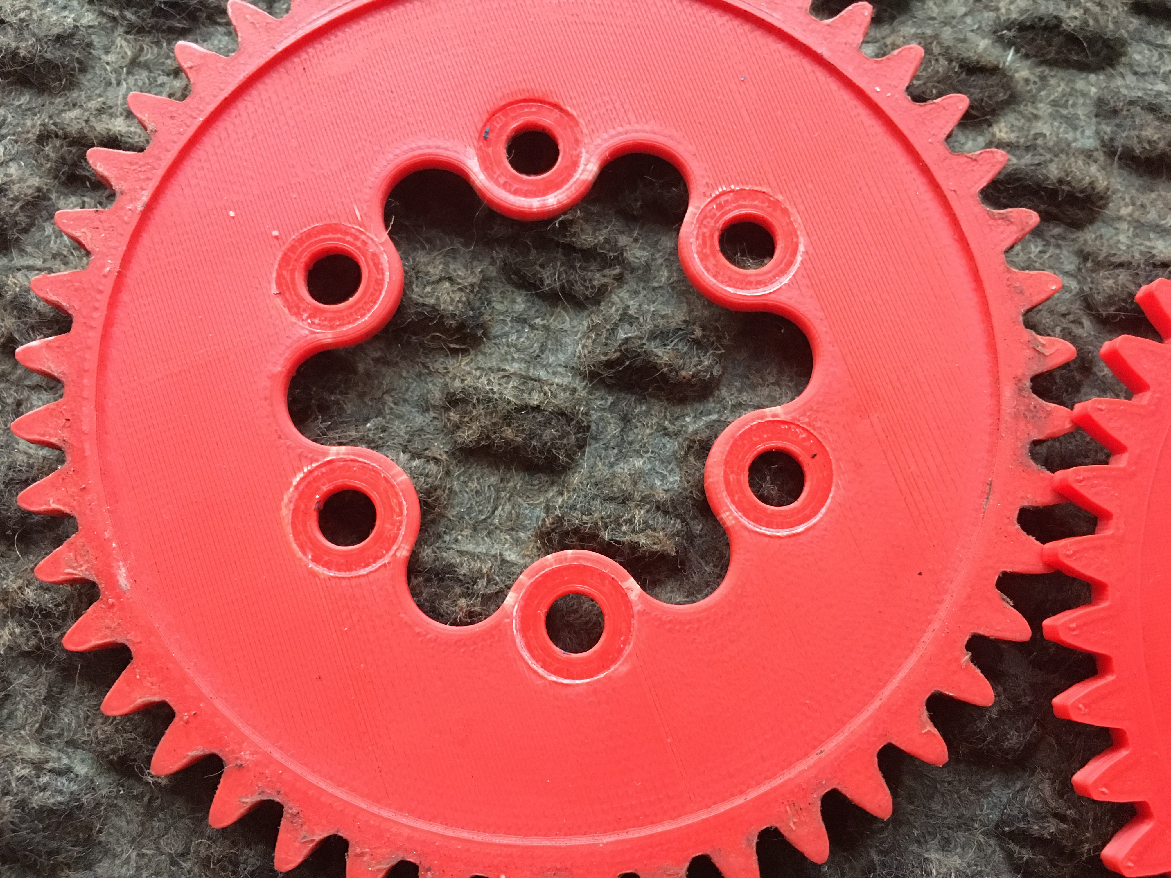
Yes, I was about to reach my working place and after an unexpected bump at 40 km/h that happened. The pinion is dirty because I tried to add some grease for noise cancellation and also for less friction as I am dealing with ABS.
That made me think. One of the main topics of my dissertation is Vibrations and Control, so let me give you a practical explanation about what (I think) really happened. Imagine you have a racket and a ball. For some reason you feel lazy and decide to attach a short elastic string to the racket and to the ball, like paddleball. Then, you start playing and I guess you will find fairly easy to predict where is the ball going to hit it.
The situation above can be described as a one Degree Of Freedom (1 DOF) system under ideal conditions, so the ball can oscillate only through one axis. That is the bike and the road. Well, now let's make it a bit more complicated by cutting the string and adding another ball (the motor + bracket). We will consider that the second ball (the furthest) is static in the air waiting to be hit. This is also know as a 2 DOF system.
The racket hits the first ball and this one will hit the second one and come back because of the string. By that time, the second one will be forced to change its trajectory while going up because the first ball came back and is being hit again by the racket. Now, the first ball will hit a MOVING second ball. That means more energy when they collide. If we add more time and also real conditions to this experiment, you will see that it is almost impossible to hit the ball because one depends on the other. In other words, this system is unstable.
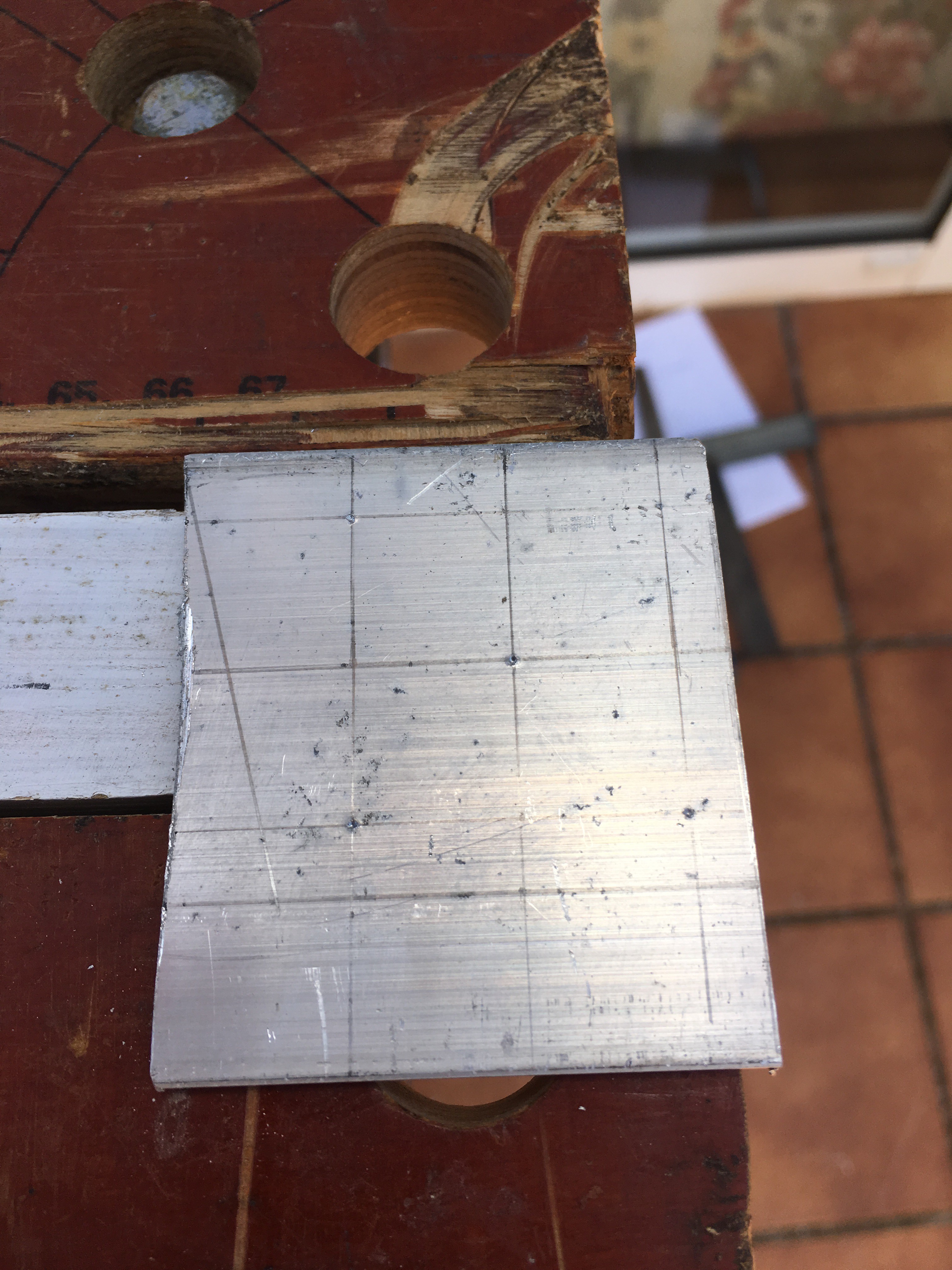
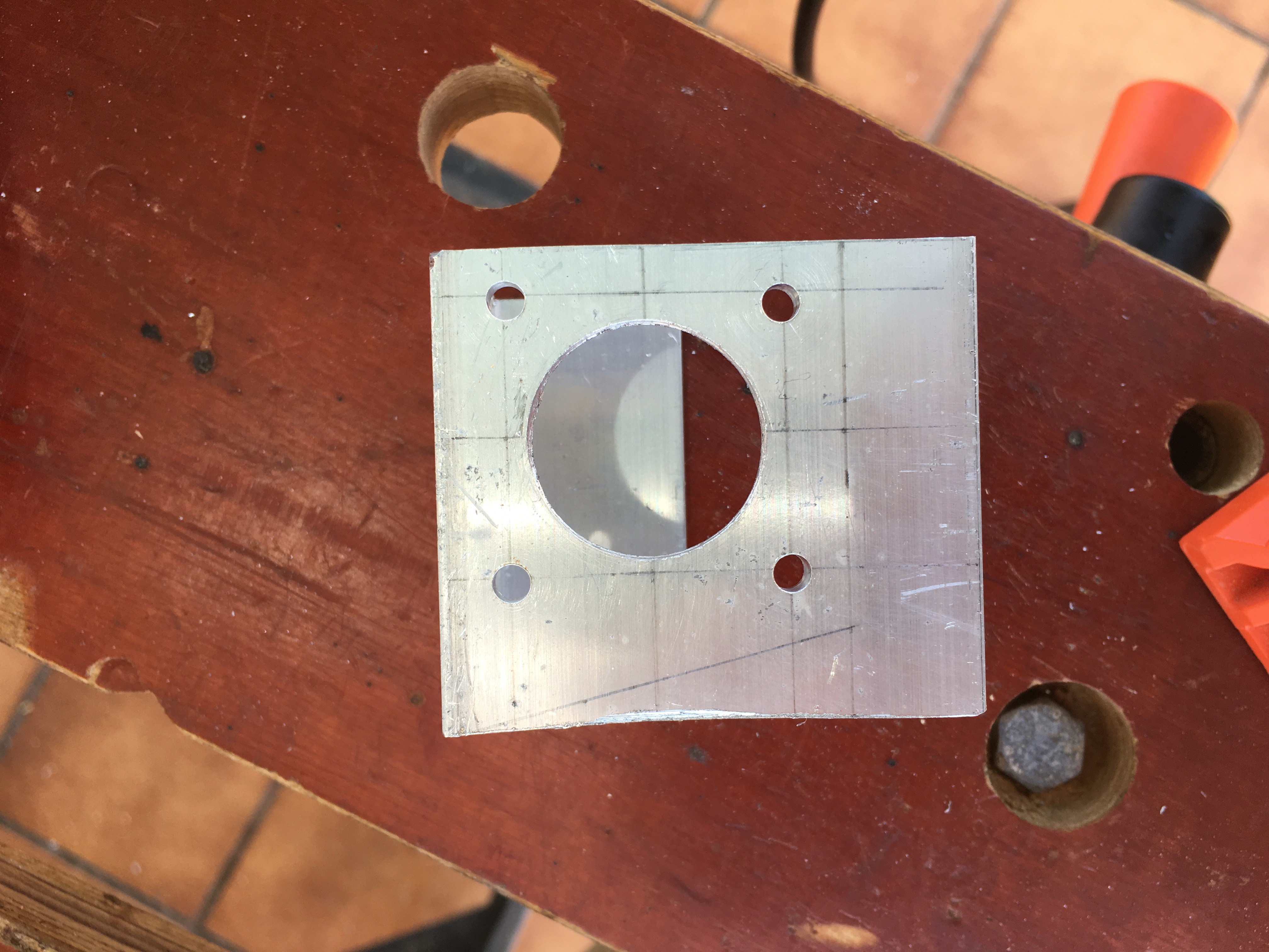
So, I had two choices: to implement a controller or make the bike + motor + bracket to oscillate as a single system. The idea of a controller is senseless since I can use a stiffer material for the motor bracket. Hence, my father had a u-shape aluminium profile back in home and cut a bit for me (pictures below).
For this part of the stage I used:
- Motor bracket drawings (GitHub)
- Angle grinder + steel disc
- Driller with several drills (from 1 to 6)
- 25mm diameter hole saw drill bit
- File tool
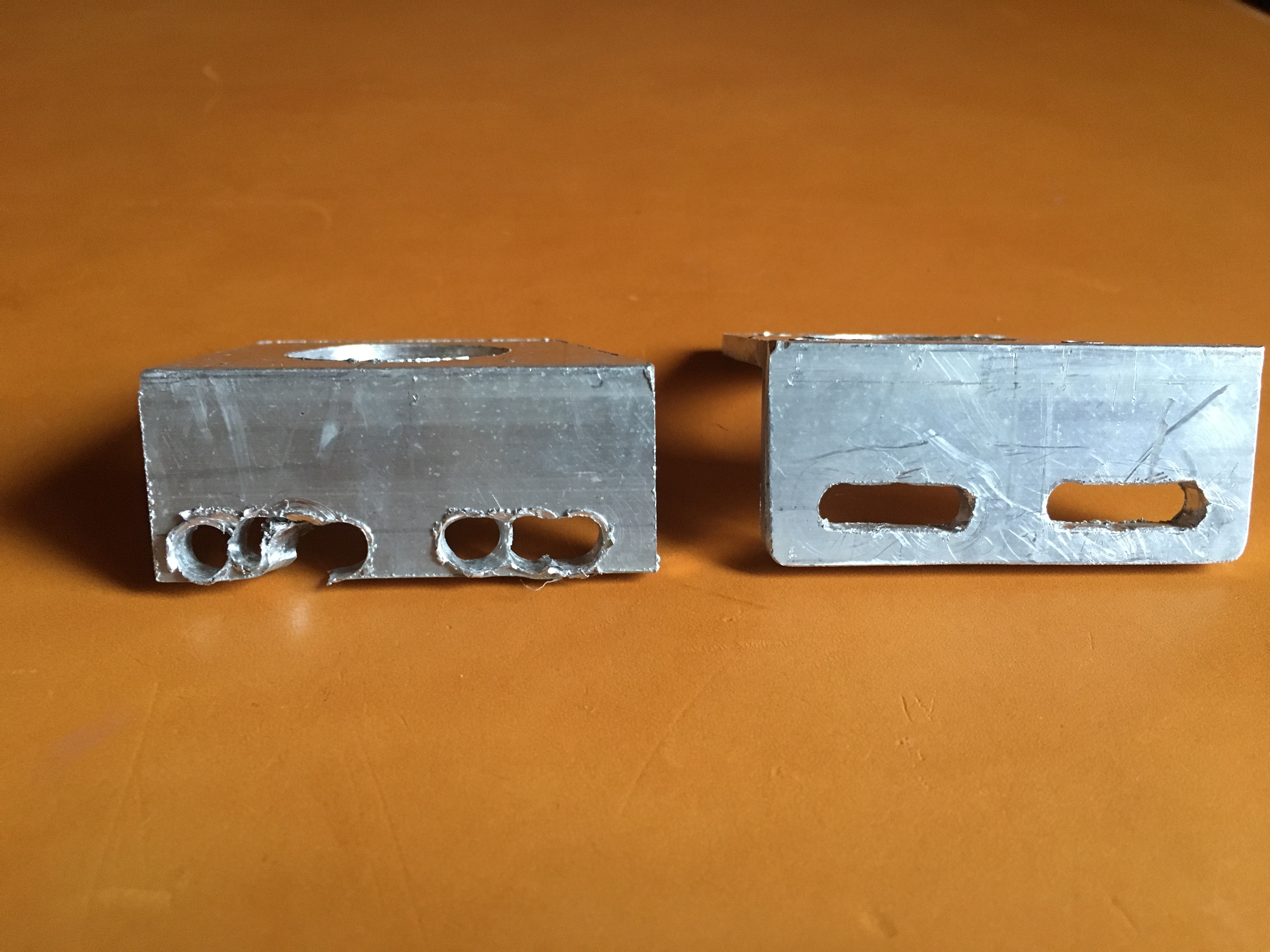
But, not everything was success! On my first try I made a little mistake by placing the bracket holes too close to the edge and this is what happened considering that tools are not perfect and I am learning:
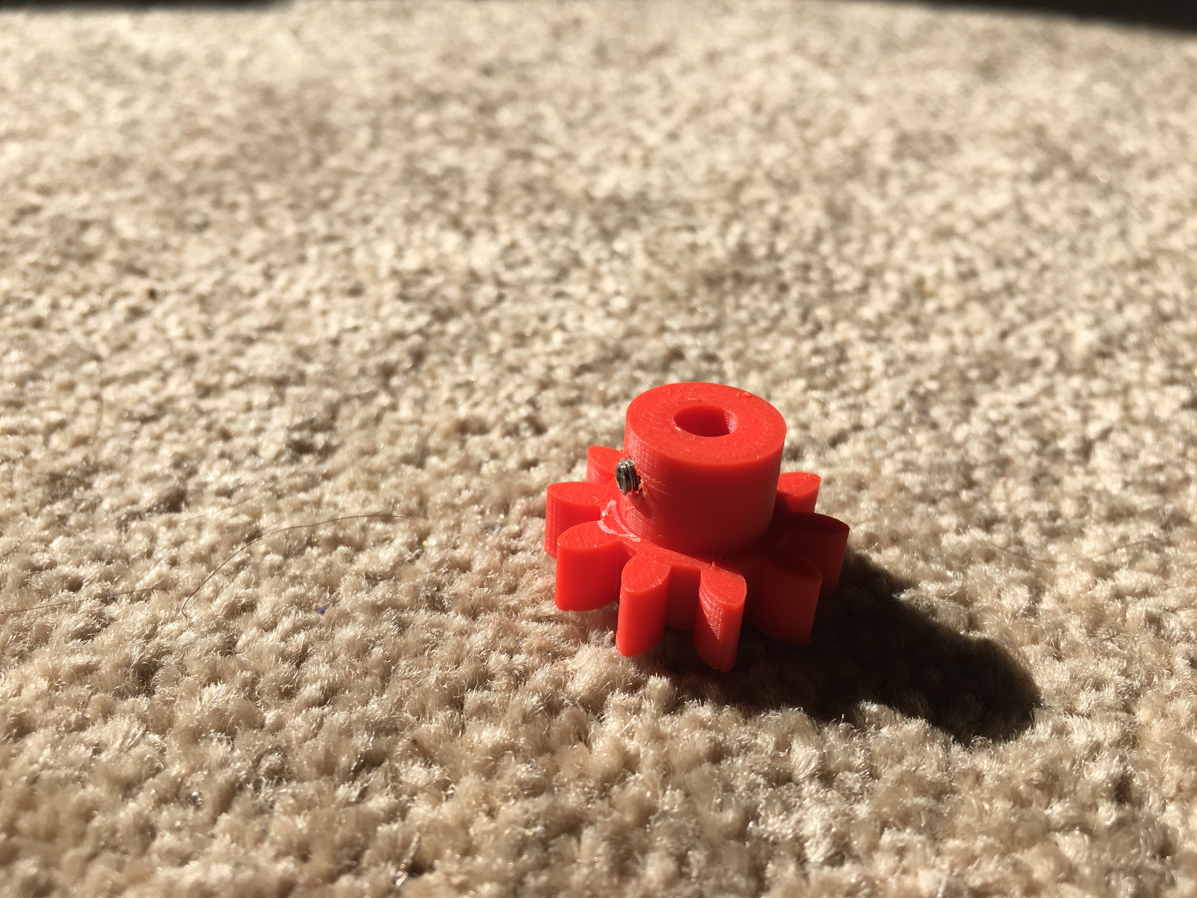
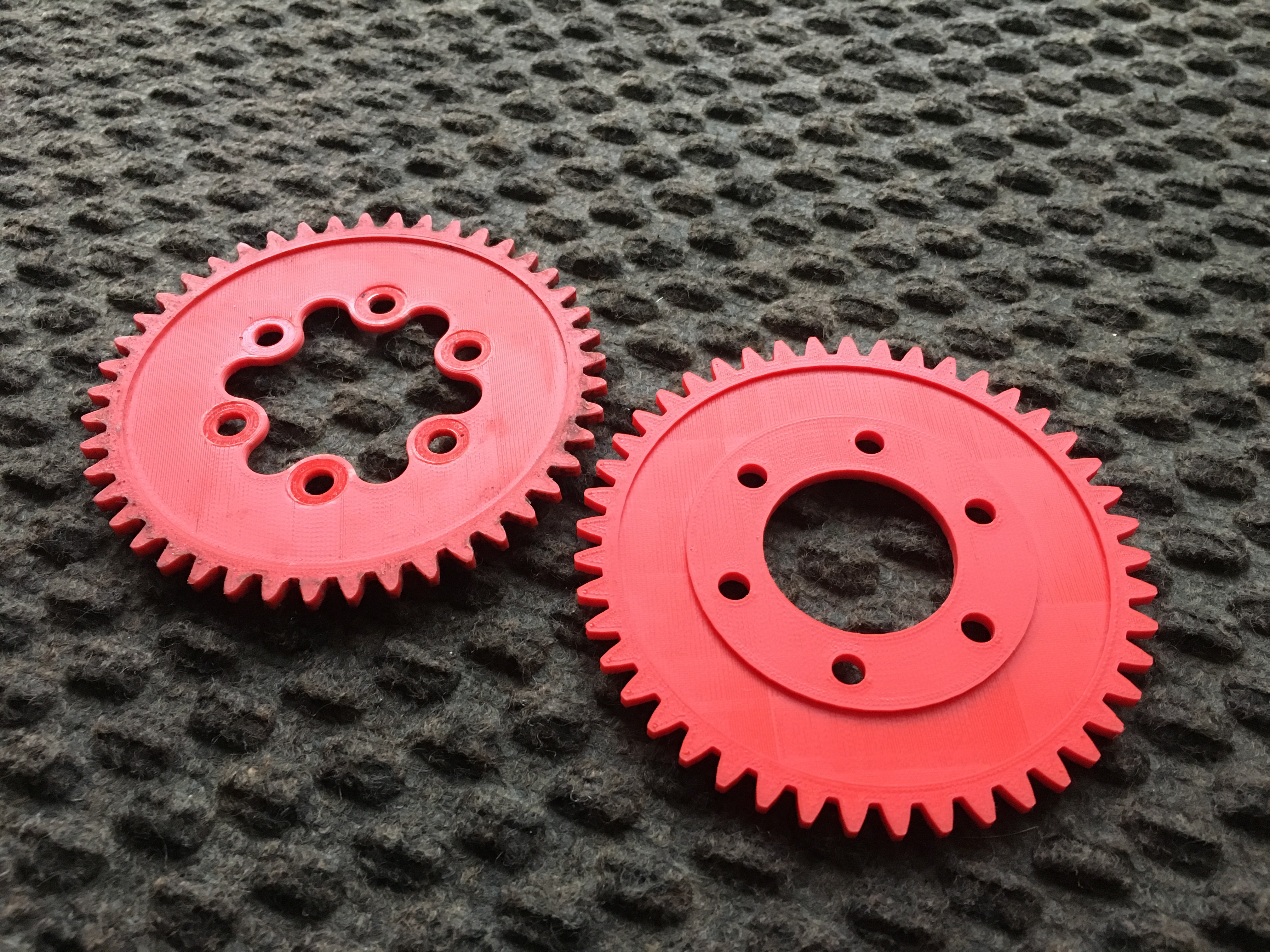
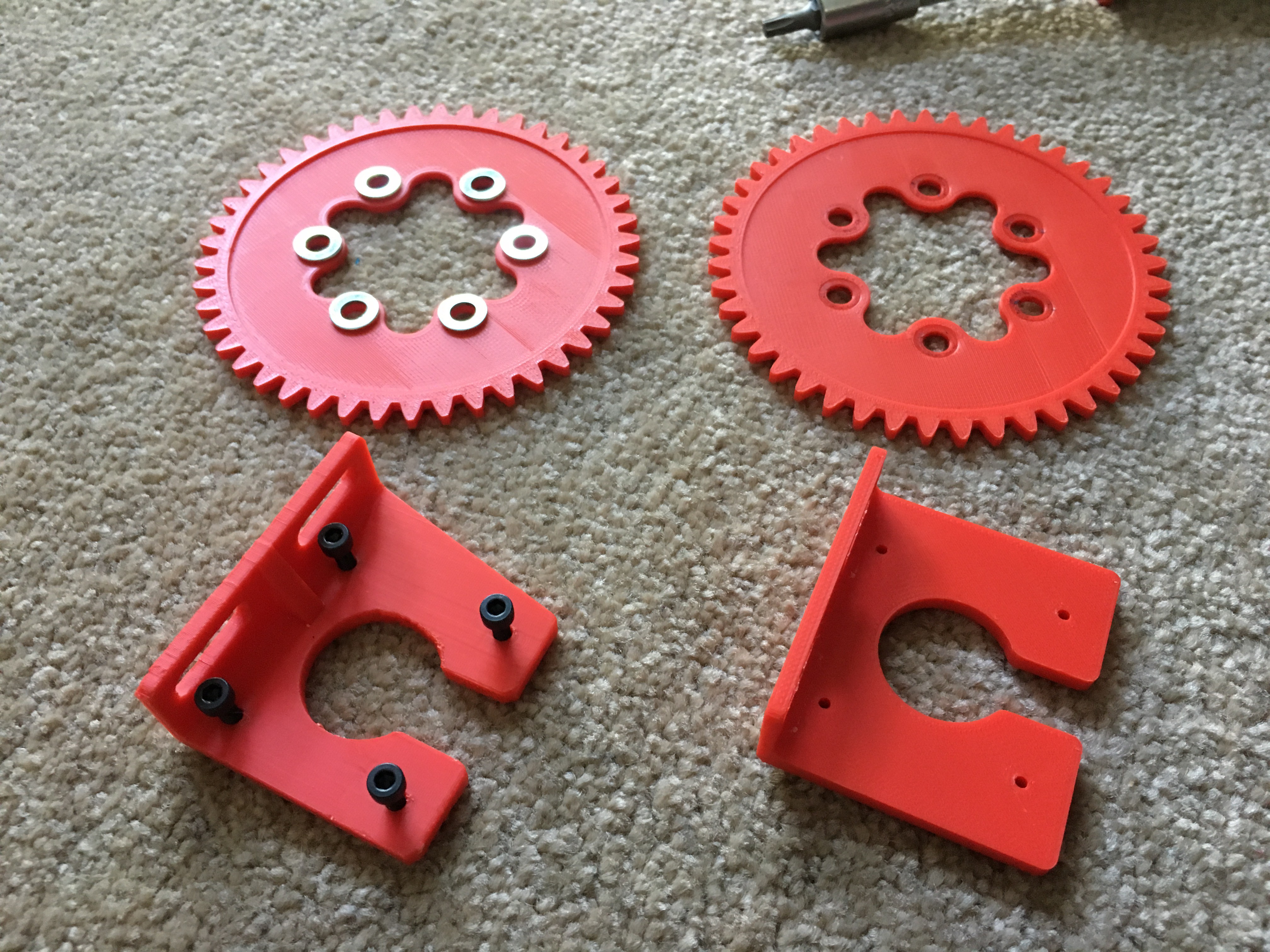
Now, regarding the pinion and spur gear I have been in touch with manufacturers here and there and none of them want to build just one unit for prototyping, which makes sense but I do not need more than one unit. I am still trying to make a deal but in the meantime I managed to reinforce both gears and make them stronger by using a full solid plastic structure and adding a grub screw to the pinion, so it will be completely fixed to the stepper shaft. Components used for this part of the stage are the following:
- Updated 3D-printed models of the reinforced gears (CAD files on GitHub!).
- 1 x M3 Allen grub screw + tool
And this is how gears looks like:
You can notice the effect of the pressure generated by the washer as it was about to break the old spur gear. You can also appreciate it in this picture:
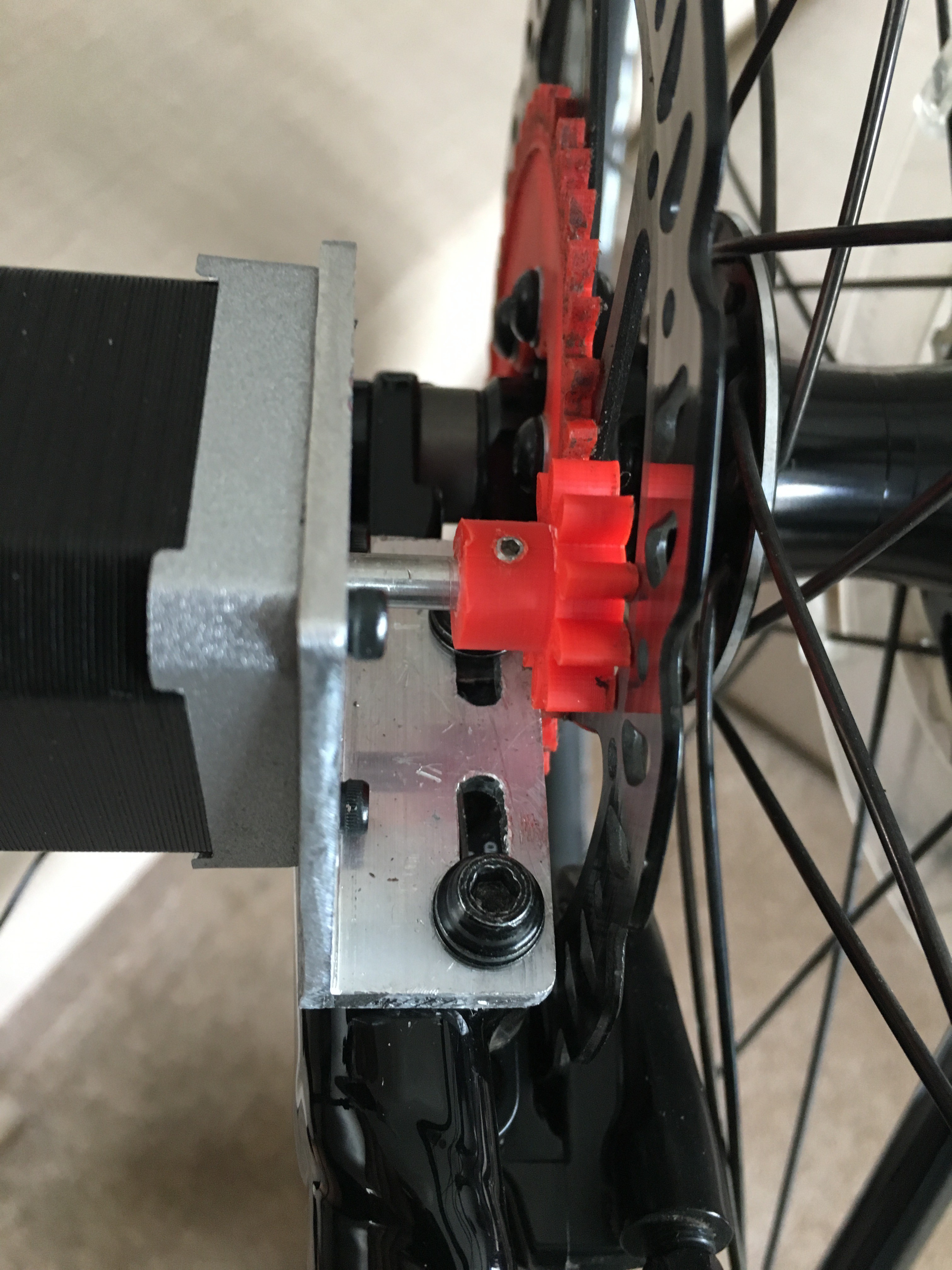
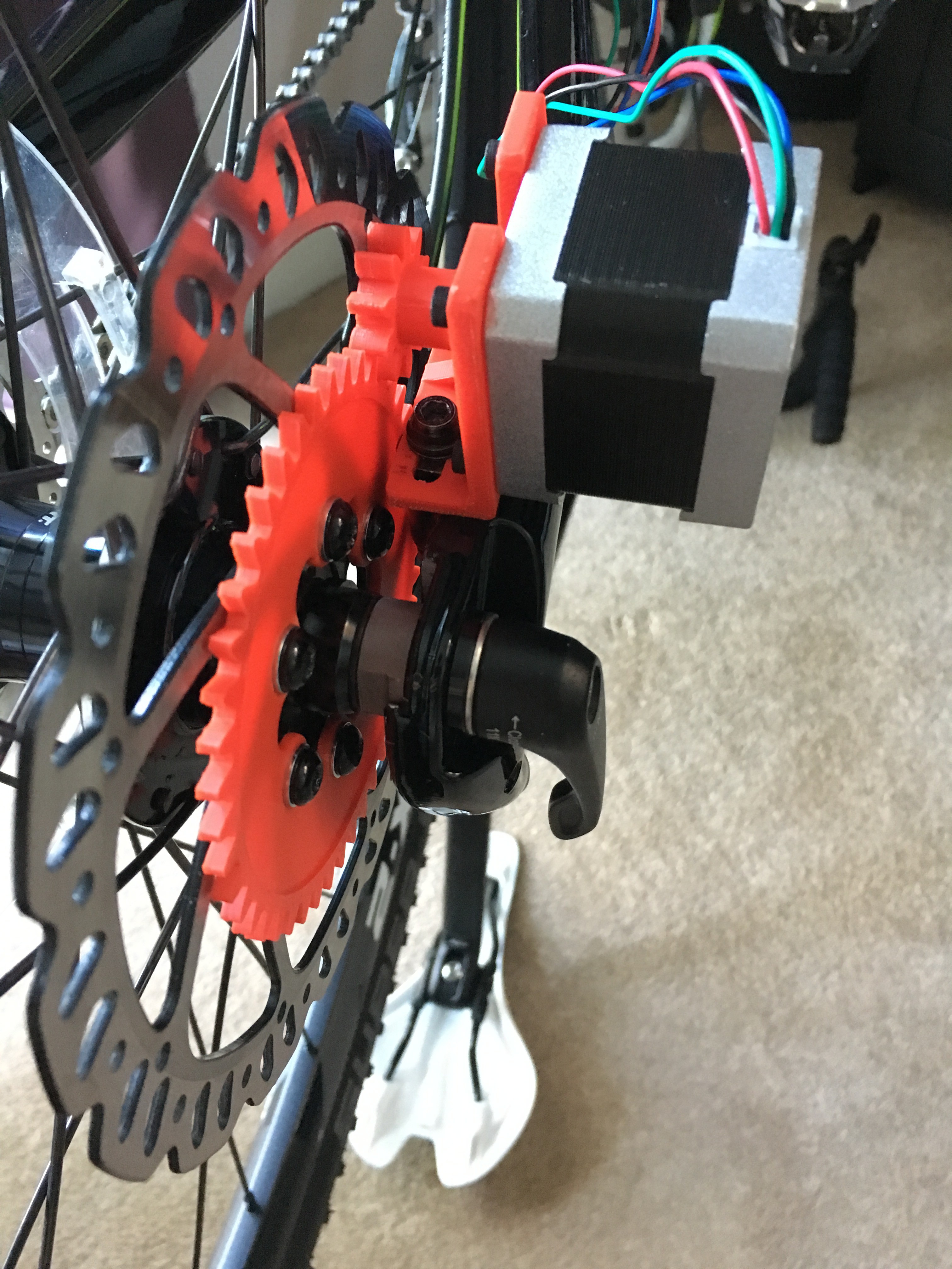
By the way, I already did more than 200km with the same gears. I think it is a very good figure considering that we are talking about medium quality 3D-printed parts!. Well, this is how it looks like on the bike!!!
I tested it on the road and...IT WORKS!!! The bike + motor bracket + stepper motor works as a single system, no oscillations at all!
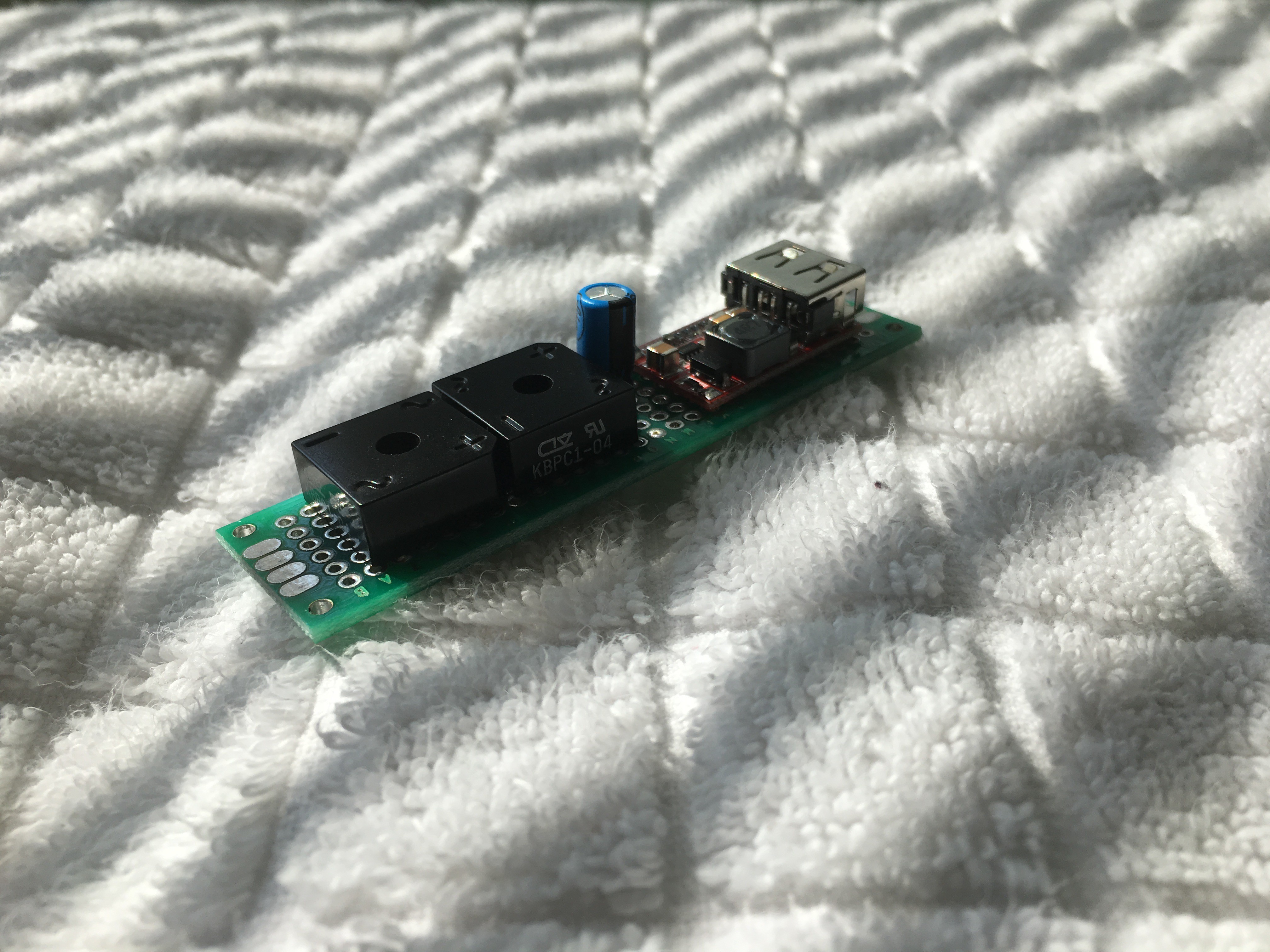
Now, the last bit for this upgrade: the rectification circuit. First of all, thank you hex4def6, electrobob and K.C. Lee for all your different ideas regarding the capacitor issue. I really appreciate it and it also made me think...a lot! I would like to share my thoughts with all of you.
I finally decided to use a 100uF@25V smoothing capacitor. I made my choice based on this post:
https://www.electronics-tutorials.ws/diode/diode_6.html
I also managed to simulate it using PartSim, but first I measured the max. voltage with no load, 50V and also the load resistance, 1.12MOhm. I also simulated it using two coils in Falstad. (Import files on GitHub):
http://www.partsim.com/simulator/#154948
Now, my options to store most of the generated energy based on your suggestions are:
- TL431 Shunt regulator - Nice option but its maximum current is 100mA, so it need to be used in conjunction with a PNP transistor to be able to handle more power. (http://www.bristolwatch.com/ccs/TL431A4.htm)
- MPPT - Excellent choice. I already bought one from Amazon (https://www.amazon.co.uk/SODIAL-Controller-Step-down-Charging-Display/dp/B076BFCGG6/ref=sr_1_3?ie=UTF8&qid=1534878476&sr=8-3&keywords=5A+MPPT) I think it would be nice to try, but it is bulky and I believe I have more choices.
- LM78XX or LM731 linear regulator - Not very efficient for this purpose as a buck converter will do the job perfectly (https://www.youtube.com/watch?v=CEhBN5_fO5o&frags=wn).
- What I had since the very beginning is a 'Step-down Buck Converter Module' (https://www.ebay.co.uk/itm/DC-6-24V-12V-24V-to-5V-3A-Car-USB-Charger-Module-Buck-Step-Down-Converter-Phone/401265883616?hash=item5d6d4f79e0:g:OjoAAOSwQctbMTOy) with the MP2315 synchronous step down converter embedded (https://www.mouser.com/ds/2/277/MP2315_r1.01-478439.pdf).
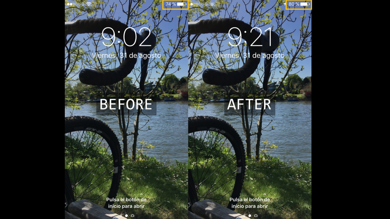
I think I am already making the most of it. To prove it I decided to quantify the amount of energy stored by charging my phone (iPhone 6S, 1,715mAh battery) instead of a power bank. Below you will find a screenshot of the phone before and after the trip:
![]()
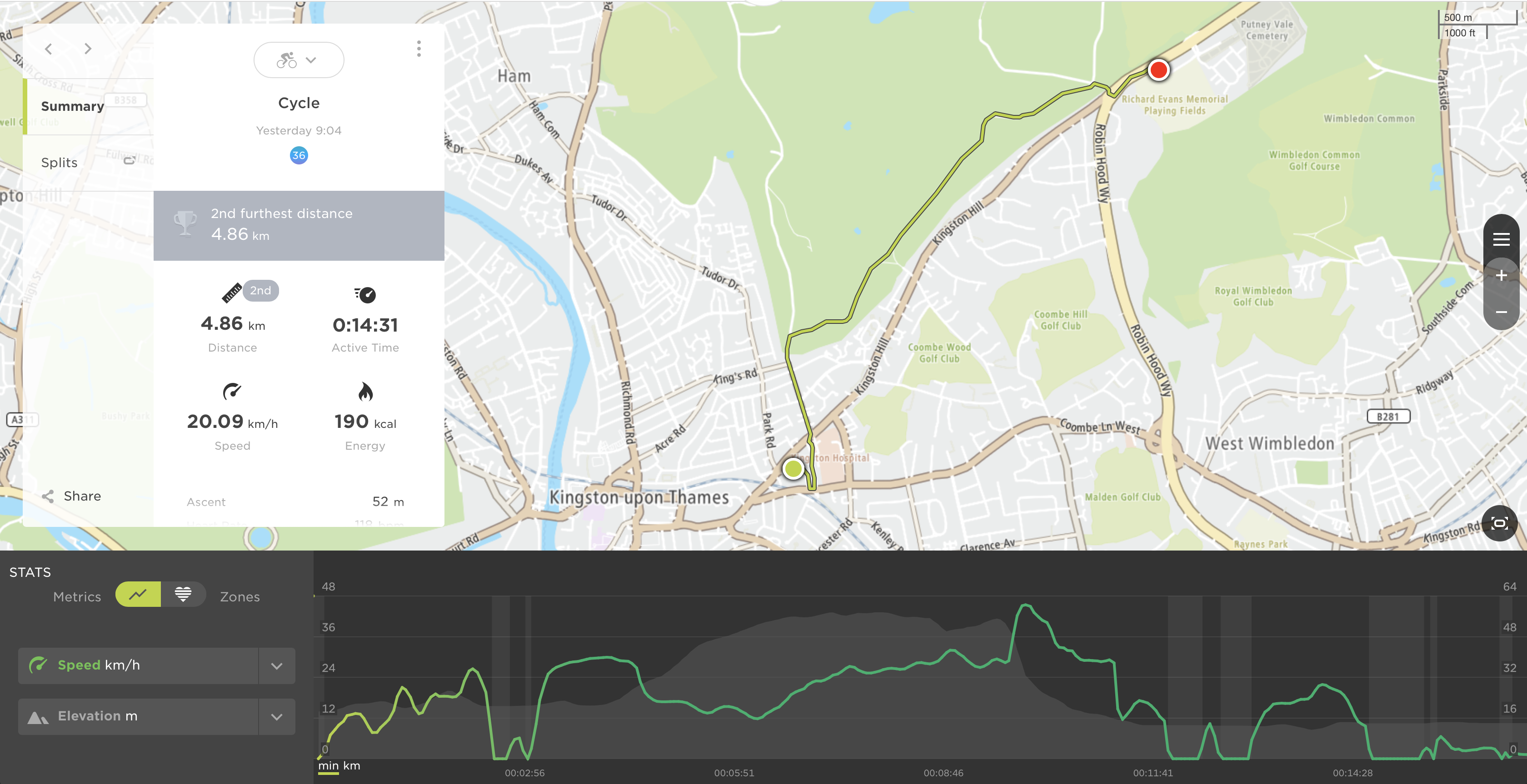
Yes, I know. I could have charged the phone for that time and that is it! That is why I decided to take my TomTom watch with me. From picture below you will be able to figure out the distance covered, time and speed:
![]()
To sum up, 4.86Km in around 15min for a 6% charge. All in all, I am very happy considering that I could have also changed the motor for the same one but more powerful (bigger coils), but I will do it once I finish the project.
Just to let you know, NO DRAG AT ALL. I cannot prove it, but I could have felt it. Thank you for spending some time reading about this entertaining adventure and I hope you like it! See you on my next log!
-
Bill of Materials
08/18/2018 at 19:11 • 0 commentsThis log entry will be focused only on all running costs. I will show all components needed per stage (tools are omitted) and the corresponding spreadsheet will be uploaded at the end of this entry.
Power Generation Stage
- 1 x Stepper Motor (17HS4417)
- 1 x JSP XPH-4 male + female + inserts
- 4 x M3 screws
- 1 x Aluminium U channel for the Motor Bracket
- 1 x 3D-printed Spur Gear
- 1 x 3D-printed Pinion Gear
- 6 x M6 stainless steel washer
- 2 x Full-wave rectifier (2W08M)
- 1 x Electrolytic capacitor (25V, 100uF)
- 1 x DC-DC step-down converter (MP2315)
- 1 x M3 Allen Grub Screw
Data Logging Stage
- 1 x FireBeetle (ESP32)
- 1 x Current sensor (ACS712-30A)
- 1 x 1 kOhm resistor
- 1 x 120 Ohm resistor
Smart Lighting System Stage
- 1 x 10x10 RGB LED Matrix (WS2812B)
- 3 x Light Dependant Resistor (LDR)
- 1 x 3D-printed Front Light assembly
- 1 x 3D-printed Rear Light assembly
- 5 x M3 screws + nuts for the headlight and rear light
- 3 x JSP 2.54mm XPH-3 housing (male + female + inserts)
eBox Stage
- 1 x 3D-printed eBox assembly
- 2 x 3D-printed Power Bank Housing
- 1 x 3D-printed eBox Mounting Bracket
- 1 x Strip Board
- 1 x Relay (SRD-05VDC-SL-C)
- 2 x Diodes (1N4007)
- 2 x USB 2.0 to Micro USB cable (1m)
- 2 x Power bank
- 1 x Single Solid Core (SSC) Black wire (0.6mmx1m)
- 1 x SSC Red wire (0.6mmx1m)
- 1 x SSC Green wire (0.6mmx1m)
- 1 x SSC Yellow wire (0.6mmx1m)
- 1 x SSC Orange wire (0.6mmx1m)
- 1 x SSC Purple wire (0.6mmx1m)
- 2 x M3 screw
- 1 x Rubber Sheet (250x250x1.5mm)
- 2 x M3 Threaded brass insert
- 8 x Neodynium Magnet Disc (3x20mm)
- 1 x Stainless Steel Rod Bar (200x2mm)
- 2 x Blue LED
- 2 x 220Ohm Resistor
- 1 x DPDT Switch
Wiring Harness Stage
- Black Heat Shrink Tube 3:1 (1m x 10mm)
- Black Heat Shrink Tube 3:1 (2m x 5mm)
- 1 x Blue Silicon AWG 22 wire (5m)
- 1 x Red Silicon AWG 22 wire (10m)
- 1 x Black Silicon AWG 22 wire (10m)
- Cable ties (200mm, 100pcs)
- Cable ties (100mm, 100pcs)
I already had some of these components, so prices will be based on current suppliers. Please, find the corresponding spreadsheet here.
-
eBox Stage
07/15/2018 at 23:21 • 0 commentsI am creating this entry in order to show you how all different stages are being merged into a main system, the eBox. The eBox is the brain of the bike, a box that gathers, process and stores all data. It also has the ability to process commands from sensors, like a car ECU (lets call it bECU)!
Hence, let me start with the diagram of the system:
![]()
Please bear in mind that this schematic may change (a lot) as I am currently creating a Prototyping Board with all modules embedded.
I would like to clarify a few things before going mad:
- D stands for 'Diode' and I will show their specifications asap.
- R stands for 'Resistor'. R1 is 1KOhm, R2-R4 are 220Ohm and R5 is 10KOhm.
- C stands for 'Capacitor'. C2 is needed to smooth power surges if any (I may remove it).
- FL stands for 'Front Light'
- RL stands for 'Rear Light'
- RI stands for 'Right Indicator'
- LI stands for 'Left Indicator'
- B stands for 'Brake'
- MS stands for 'Main Switch'
Q&A Section
How many controllers are being used on this project?
At the moment only one. However, I could appreciate some lag when testing the light system. I will merge all the code and see how it goes but I believe one MCU will be for data logging an another one for the system management.
Why a diode in the Vin pin?
From previous experiences I have observed that Vin also provides 5V. This will avoid any possible issue.
A box in a bike like in the pictures?
Well, yes and no. I need a waterproof container to install all the electronics. This eBox needs to be compact, modular, small and also needs to use a common fixation point that all bikes have. The bottle cage mounting point is my first choice.
I know, it is still a box but I have some nice designs in mind, and you should be able to still use the mounting point for its original purpose.
UPDATE - 6/10/18
I have made lots of changes regarding the electronics and I would like to explain all of them in a new log entry as I am leaving this one for reference. It is always nice to see a 'before' and 'after' picture.
Please, find the new and updated log entry here: eBox Stage 2.0
-
Smart Lighting Stage
07/15/2018 at 21:32 • 0 commentsIt is time to upgrade the current setup with a smart lighting system!! The aim here is to use one of the batteries to power up a headlight and a rear light. One of the three Light Dependant Resistors (LDRs) will be used to sense the environment. The other two will be used in order to decrease the light intensity when another car/bike is coming from the opposite direction. Another functionality could be that the front and rear lights will start blinking to make sure that the car spots the bike.
On the other hand, I would like to outline the usage of programmables LEDs. You can literally program anything! And I have some ideas in mind...I will keep you updated.
Please find below the list of components needed for this stage:
- 1 x 10x10 RGB LED Matrix (WS2812B)
- 3 x Light Dependant Resistor (LDR)
- 1 x 3D-printed Front Light assembly
- 1 x 3D-printed Rear Light assembly
- 5 x M3 screws + nuts for the headlight and rear light
- 3 x JSP 2.54mm XPH-3 housing (male + female + inserts)
- Different sizes of heatshrink
- Hot glue gun
- Soldering iron + soldering material
- Patience and be willing to improve your soldering skills!
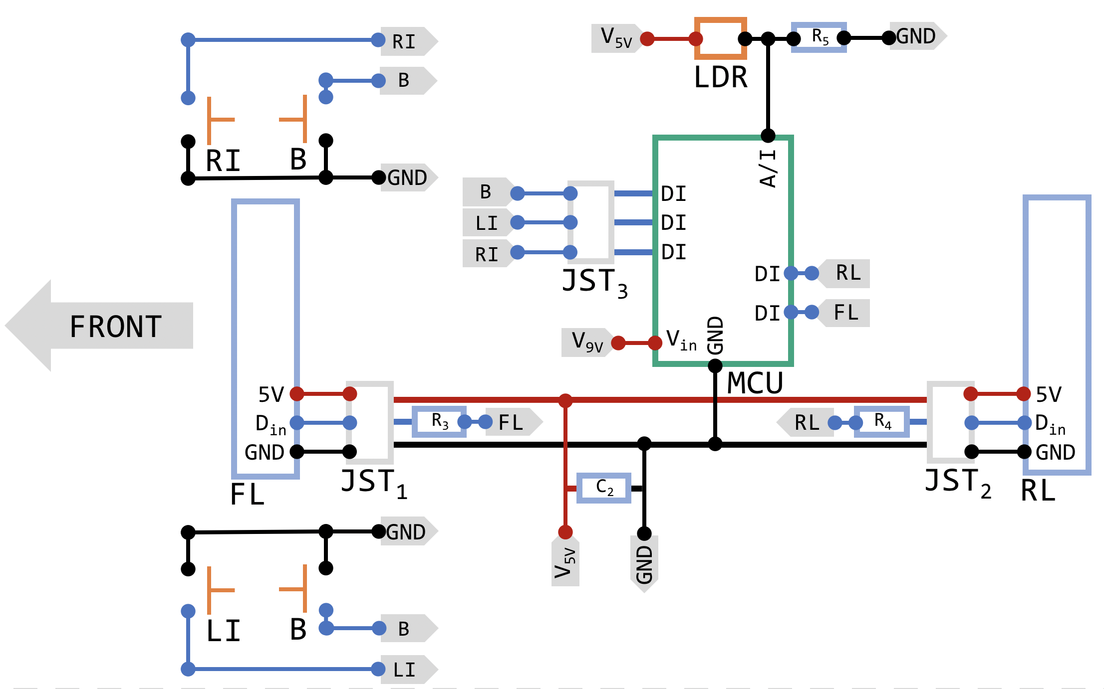
First of all, I would like to show you the schematics of this stage. As I mentioned before, my aim is to show you how I am building this system, not to teach you how schematics should be represented.
![]()
Having said that, I want you to imagine that you are currently on the bike. Now, I guess the arrow labeled as 'FRONT' makes sense. I know I mentioned 3 LDRs and I am showing only one as I managed to implement this one (I need more time!) only but the setup for the rest of them should be the same. Below you will find the list of abbreviations:
- RI - Right Indicator
- LI - Left Indicator
- B - Brake
- FL - Front Light
- RL - Rear Light
Let's start with FL and RL. I tried to make a simple design for ease of printing. However, it is not an easy task if we start thinking about the number of wires coming out and how to route them. Let me tell you something, I hate wires as they really affect aesthetics and no matter how you sort them, they are not part of the design when you first think about it. Wire routing is art, so my plan is to make them disappear!
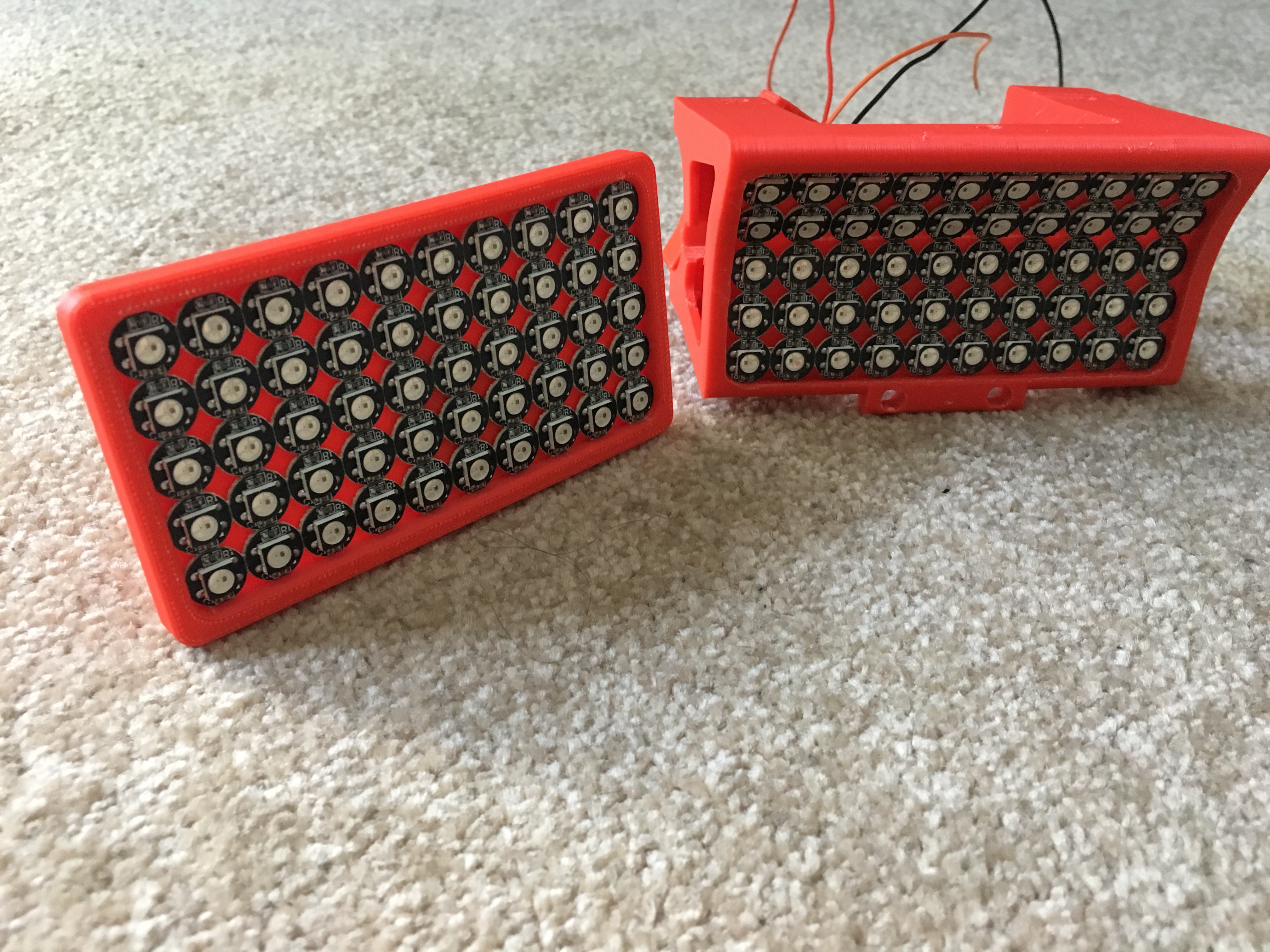
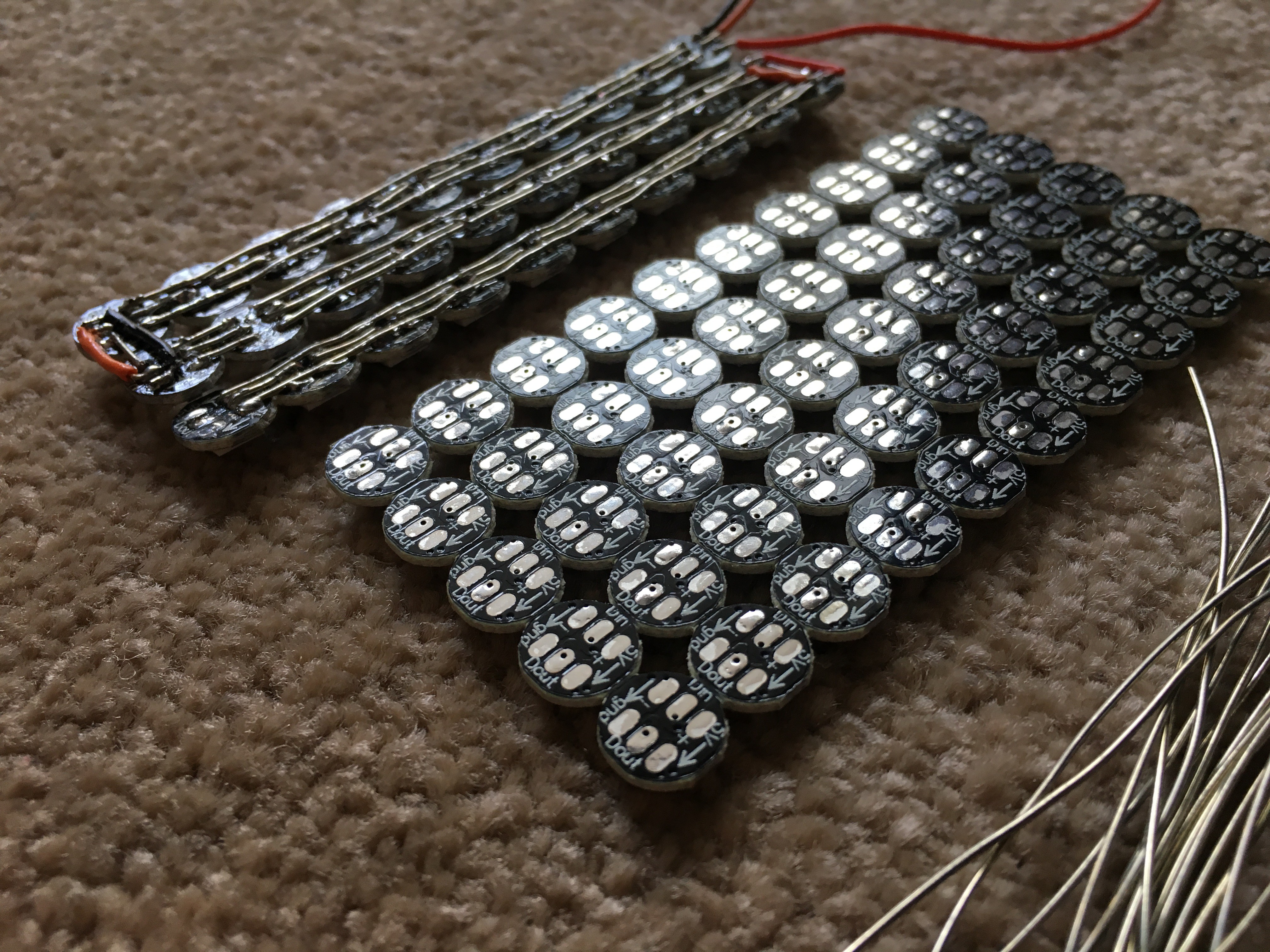
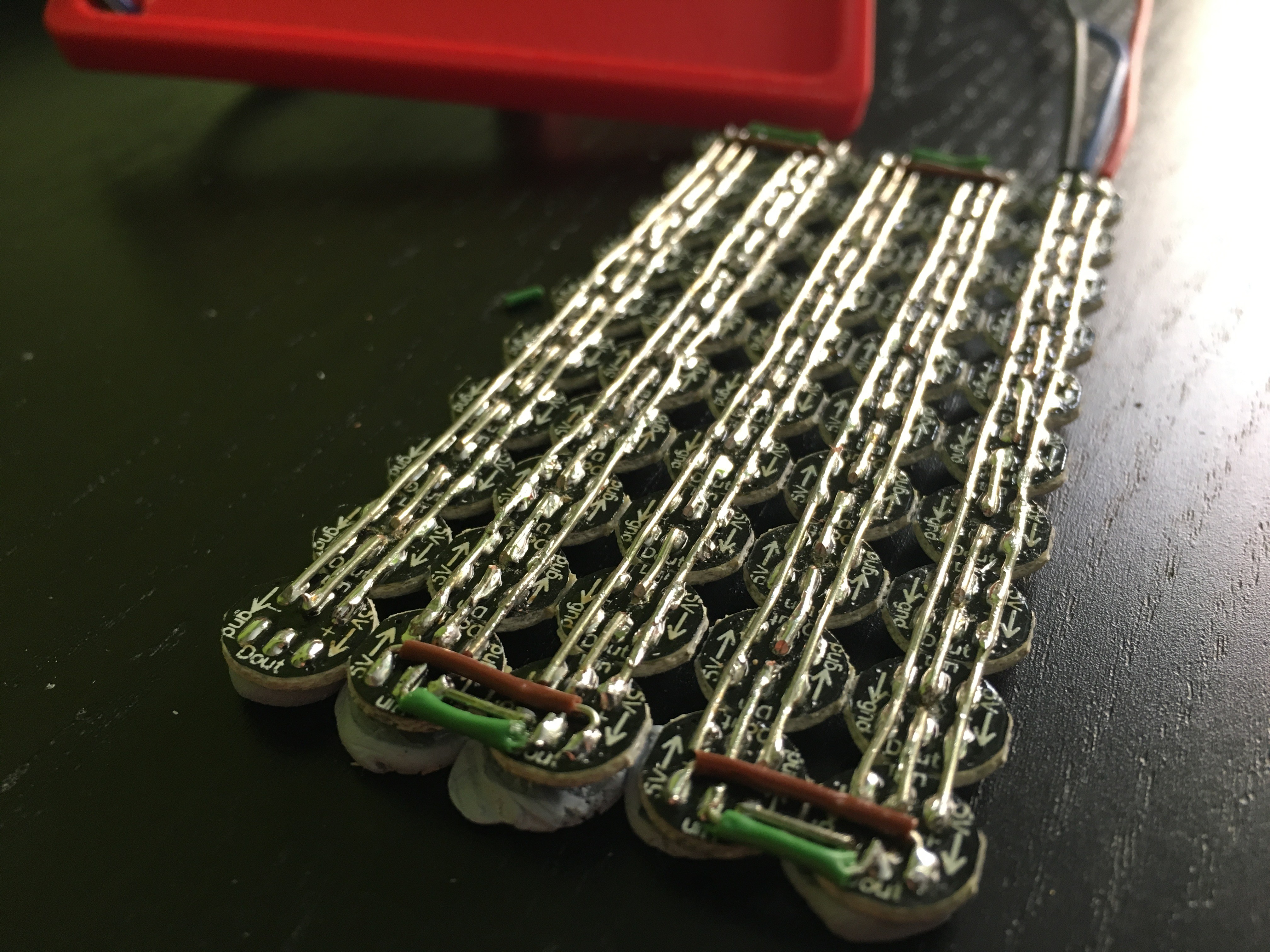
As it can be seen, I have also added the LED matrix, but all rows still need to be connected. Now, patience and start soldering! I will treat the LED matrix as a single LED stripe, so only one 'for' loop will be needed to address all of them instead of two (rows and columns).
The best way I found to solder this LED matrix is to use some 'blu tack' or similar, so the matrix will be firmly attached to the bench.
Next step was to find a good library for Arduino. FastLED seemed to be a great choice, so I decided to check each LED to see if all of them are well connected. There is an example named 'Blink' that can be used to activate one LED each time and also to get familiar with the library itself. If you want to go further, I would suggest you to add a potentiometer to the setup, so you should be able to activate as many LEDs as you want by adjusting the knob.
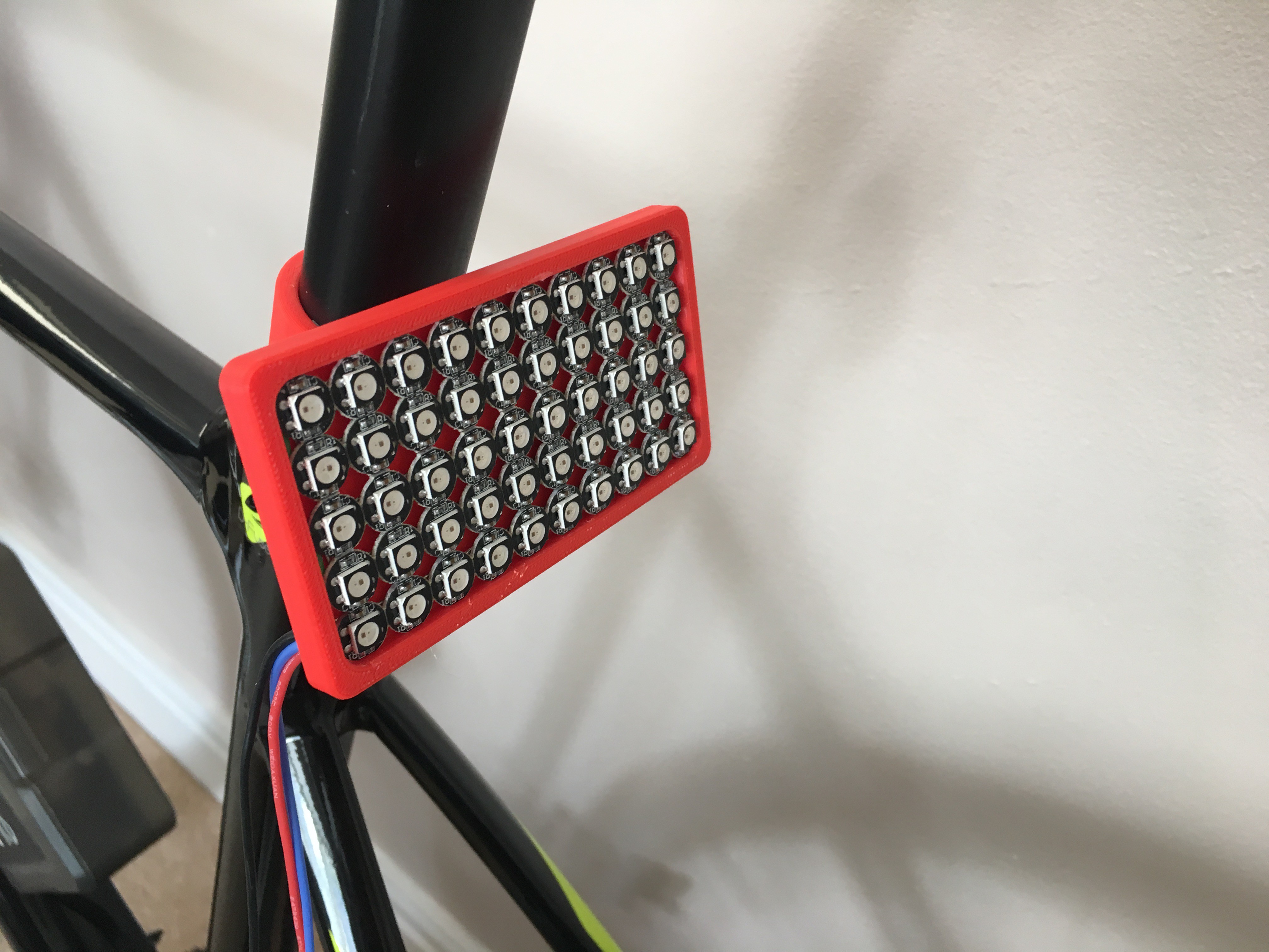
I have to say that it was a pain!! Well, I managed to finish, so let's see how it looks like o the bike, but first check out the coupling system of the headlight. Different brackets would make it easier to adapt the system to other bikes. As it can be seen, two rows of headlight were tilted 30deg to provide light close to the bike too. I will give further details on this idea as soon as I test the light on real conditions.
I know they are very basic and it would be nice to make nicer designs, but I am now focused on making a working setup first.
As the last step, I decided to add four pushbuttons on a breadboard (emulating indicators, front light and brake light) and test my code. I had to make use of interrupts as you may see in the code and pushbuttons are internally set as pull-up inputs. I also tried to make it as simple as possible, so feel free to ask me if you have any question. I am still working on this stage, so please bear in mind that the code is not finished yet.
Now it is time to explain how I designed all different functionalities for lights. Let's start from basics... I know I am very repetitive, but I tend to forget and freak out:
Braking light - brakeLight()
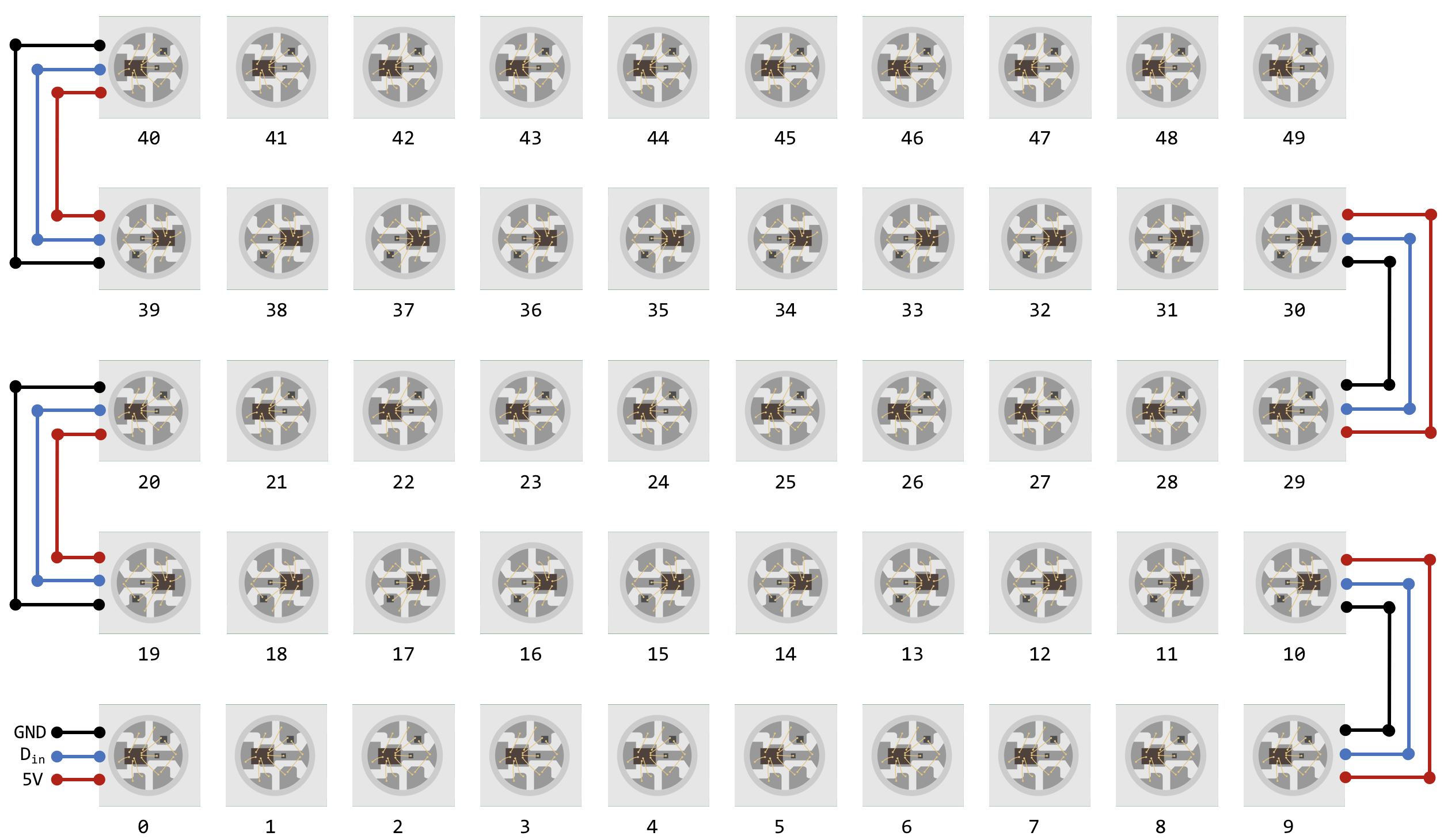
If you scroll up and check the diagram, the braking light circuit is just two pushbuttons connected to the same digital input pin. Hence, the braking light should be activated if any of the pushbutton is pressed. I am treating the WS2812B matrix as a single row of 50 LEDs, so the index should go from 0 to 49. Please see the diagram below, as graphics always help.
![]()
And here is the function that activates all LEDs in red:
void brakeLight(int k){
  FastLED.setBrightness(k);
  for (int i = 0; i<NUM_LEDS;i++){
  Rleds[i].setRGB(255, 0, 0); //Rleds - Rear Light LEDs
  FastLED.show();
  }
}
Beam Light - headLightOn()
Now that the braking light is working, you should notice that when the beam light is activated on a car, the braking light also does but with reduced brightness. In other words, another if statement should be enough to activate both lights at the same time. Here is the code for the beam light:
void headLightOn(int k){
  FastLED.setBrightness(k);
  for (int i = 0; i<NUM_LEDS;i++){
  Fleds[i].setRGB(255, 255, 255); //Fleds - Front Light LEDS
  FastLED.show();
  }
}
Indicators- indicatorOn()
Let's begin with a bit of a challenge! This is not hard because of the coding part, this is hard because you need to make it work! I love Audi's light matrix and I thought - why not?! It should be easy to switch on/off LEDs in cascade mode. In other words, on...off...on...off...got it!
After several trials, I managed to use only one function to activate the headlight and the rear light saving memory and reducing code lines!
void indicatorOn(int z,int j) {
  FastLED.setBrightness(20);
  for (int i = 0; i<=5;i++){

    //Front Light
    Fleds[(5-z)-i*j].setRGB( 255, 30, 0);
    Fleds[(14+z)+i*j].setRGB( 255, 30, 0);
    Fleds[(25-z)-i*j].setRGB( 255, 30, 0);
    Fleds[(34+z)+i*j].setRGB( 255, 30, 0);
    Fleds[(45-z)-i*j].setRGB( 255, 30, 0);

    //Rear Light
    Rleds[(5-z)+i*j].setRGB( 255, 30, 0);
    Rleds[(14+z)-i*j].setRGB( 255, 30, 0);
    Rleds[(25-z)+i*j].setRGB( 255, 30, 0);
    Rleds[(34+z)-i*j].setRGB( 255, 30, 0);
    Rleds[(45-z)+i*j].setRGB( 255, 30, 0);
    FastLED.show();
    delay(70); //Delay for cascade effect
  }
  delay(200); //Delay to start switching off with the same effect

  FastLED.setBrightness(20);
  for (int i = 0; i<=5;i++){

    //Front Light
    Fleds[(5-z)-i*j].setRGB( 0, 0, 0);
    Fleds[(14+z)+i*j].setRGB( 0, 0, 0);
    Fleds[(25-z)-i*j].setRGB( 0, 0, 0);
    Fleds[(34+z)+i*j].setRGB( 0, 0, 0);
    Fleds[(45-z)-i*j].setRGB( 0, 0, 0);

    //Rear Light
    Rleds[(5-z)+i*j].setRGB( 0, 0, 0);
    Rleds[(14+z)-i*j].setRGB( 0, 0, 0);
    Rleds[(25-z)+i*j].setRGB( 0, 0, 0);
    Rleds[(34+z)-i*j].setRGB( 0, 0, 0);
    Rleds[(45-z)+i*j].setRGB( 0, 0, 0);

    FastLED.show();
}
}
The first thing I need, is to figure out where do I want to set my starting point, which is one column further than the middle column, where LED 5 is. If LI is activated, LEDs corresponding to that column are 5, 14, 25, 34 and 45 and the index needs to go from 0 to 5 as establishing a numerical relationship between the aforementioned numbers is not recommended. The index increases in some of the rows while decreases in others (yes, go back and check the diagram). However, if RI is activated, LEDs corresponding to that column are 4, 15, 24, 35. Now the addition of 'z' makes sense as its values will be 1 for RI or 0 for LI.
Another parameter (j) is introduced to define the direction (left, -1, or right, 1) depending on which indicator is activated. Bear in mind that both lights have exactly the same layout, hence they need to have opposite signs for the indexing.
Let me show you a video of different functions I managed to program. I could not add all LDRs as I am still working on this stage.
Next update I will show you a fully working smart lighting system...on the road!
UPDATE - 01/09/2018
I know it has been a while, I am sorry. My health condition was not the best in the last two months but now I am fully recovered!
Minor changes have been carried out on the smart lighting system:
- I managed to have a fully working LDR for environment light sensing. However, when the beam light is activated, the brake light flickers. Maybe using an Arduino Uno/Nano is not enough or my way of programming is not the ideal one for this case. Anyway, I am currently optimising the code to make sure that it is robust and it does the job properly. You can find it on GitHub!
- I am planning to upgrade the controller too. I am currently testing my code with a lot of issues. It is very annoying and very time consuming... BUT I AM LEARNING! I will leave it there as this controller brings more features...
- I had some wiring issues with the LDRs and I spent some time redesigning it. The headlight works very well, but one of the LEDs needs to be soldered again. That is going to be a proper pain. I am currently working on it!
Q&A Section
Are you planning to update the headlight and rear light models?
That is for sure! As I mentioned before, I am working with very simple and easy to make designs. On the other side, the headlight requires a lot of time and material. I decided to make the least prototypes as possible as this world is already facing a huge problem with plastic waste. I would love to use recycled plastics for this models, using methodologies like in Preciousplastic while considering the amount of energy spent to recycle and how to generate energy using alternative ways.
-
Data Logger Stage
07/06/2018 at 08:17 • 0 commentsIn this part of the project I am going to focus on building and calibration of the data logger for the bike. I would like to measure the current generated at a certain voltage and save it on a uSD card module. From there I should be able to get the power generated on each trip. In other words, I should be able to validate my setup!
I know I could add GPS, speedometer and cadence sensors, but we are on the wearable era! I think it is more useful to use your watch rather than add a lot of circuits to your setup that would increase the space needed, the cost of the overall project and will also use more energy. This could be saved for future implementations, but for now lets stick to basics. First walk and then... run!!
Components needed:
- uSD card reader module for Arduino (or similar).
- 2 resistors to build a voltage divider
- ACS712-30A current sensor or similar
- Arduino MCU or similar
- Single Core Solid (SCS) wires
- Time...plenty of time!
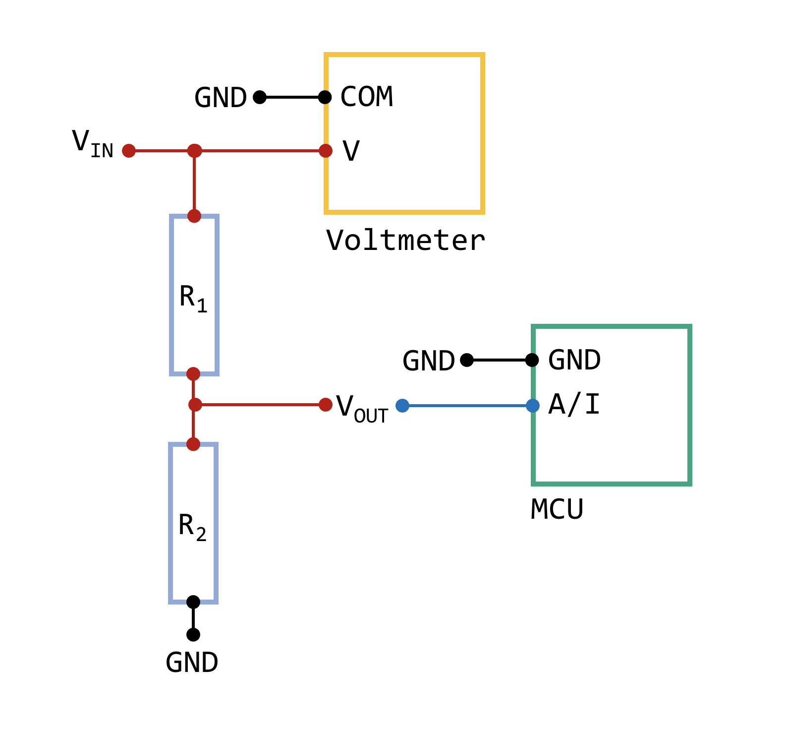
VOLTMETER (voltage divider)
My question at this stage was very simple, how could I build an accurate voltmeter with a voltage divider? And I found out that it depends on a lot of factors, so...hands on with electronics!
![]()
My aim with all diagrams at this stage is to show you how I did things (the big picture). I am not trying to draw ideal and standardised schematics as I believe it would be harder to understand. Who knows if the next 'Einstein' will read this and based on the level of difficulty will give up or continue learning about these little things! In other words, things as simple and easy as possible. It will help others to discover new areas of interest.
Coming back to the main topic, it is possible to design a digital voltmeter with two resistors in series (voltage divider). If you have a look on the diagram, I have also connected a standard voltmeter in parallel, so I can validate my voltmeter. I finally attach Vout wire to an Analog Input (A/I) on the Arduino.
Now lets look at this setup in a more 'specific' way. A/I pins on the Arduino are able to read a signal of max. 5V and the resolution of the Analog to Digital Converter (ADC) is 10 bits or 1024 divisions (2^10 bits = 1024 divisions). Remember that in programming the range would be from 0 to 1023 divisions. In my case, I am planning to read a maximum of 25V for safety, so Vin will be 25V. Vout should be less than 5V, so I set Vout to be 4V when Vin is 25V. That is how a voltage divider 'should' work.
Next step...resistors! (R1 and R2). I had available some 1 KOhm resistors, so I grabbed a multimeter and measured its real value. The real value for R1 was 994 Ohm. Now, I assume that there is no multimeter and MCU in the diagram. Applying Kirchhoff's voltage law we get two equations and two unknowns:
Rearranging,
An this is how the value of R2 is calculated. In my case, the ideal value of R2 should be equal to 189.3 Ohm. As it is fairly difficult to find a standard resistor with that value, I decided to approximate the value so R2 is 220 Ohm. Wait a second! Grab the multimeter and measure the real resistance! The real value for R2 was 217.3 Ohm. Now it is very important to check that Vout will never reach 5V, so rearranging from above equations:
If the value is less than 5V, you are good to go (mine was 4.4898V).
Now, last thing before proceeding with the calibration as with this little tweak you will avoid a huge headache. If you connect Arduino to the computer (as we all do) and check voltage in Vref pin by choosing GND as the the usual Arduino one, you will realise that this voltage is less than 5V. In other words, if Vref is different, readings will also be different. The general solution for me was to apply a consistent voltage signal through Vin pin on Arduino. What a good chance to start using my power bank (the original power source)! As it is able to provide a max. of 5V and I need 7V minimum and 12V max. (check MCU specifications) I had to add a step-up DC converter. From trial and error I found that 9V is enough, so readings are not altered when adding more devices.
Regarding the calibration, I had the chance of using a nice and reliable PSU where I currently work. Therefore, my aim was to make 100 readings from Arduino, make an Excel spreadsheet (attached soon!) with readings for each voltage increment and note the real voltage value with the multimeter. Excel has a nice feature to compute a trend line form a graph, so you should be able to figure out the gain (sensitivity) as the graph should be linear. No worries, Arduino code will be uploaded.
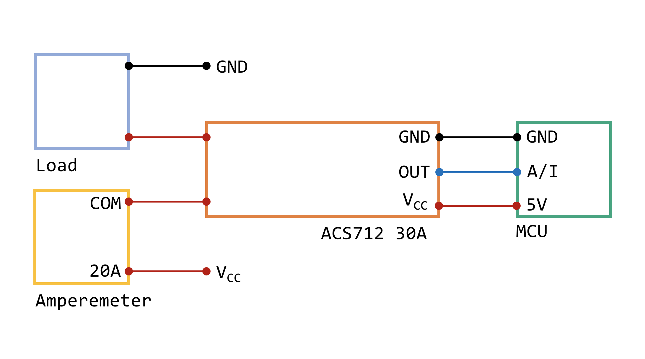
AMPEREMETER
![]()
As it can be seen, it is almost the same as the voltage divider but in this case, the multimeter is set as amperemeter. I am using the ACS712-30A hall effect sensor because I already had it, but I am sure you can try using two resistors in parallel.
The output from the module is given in mV, so the main task will be changing from divisions (div) to mV and convert it to A using the sensitivity coefficient. Please, feel free to check the data sheet for more information here.
This particular module can measure from -30A to 30A, so 511 div should be our 'zero' point. This is aka offset and has a value of 2500mV (it makes sense!). Another essential aspect is the sensitivity, which is 66mV/A for this module. Remember to check that Vref on the Arduino has a stable voltage of 5V or similar, so you will avoid unreliable readings.
All in all, we are in a unit conversion problem, so lets name the output of the sensor as in the diagram (OUT) and 'CS' the output in A:
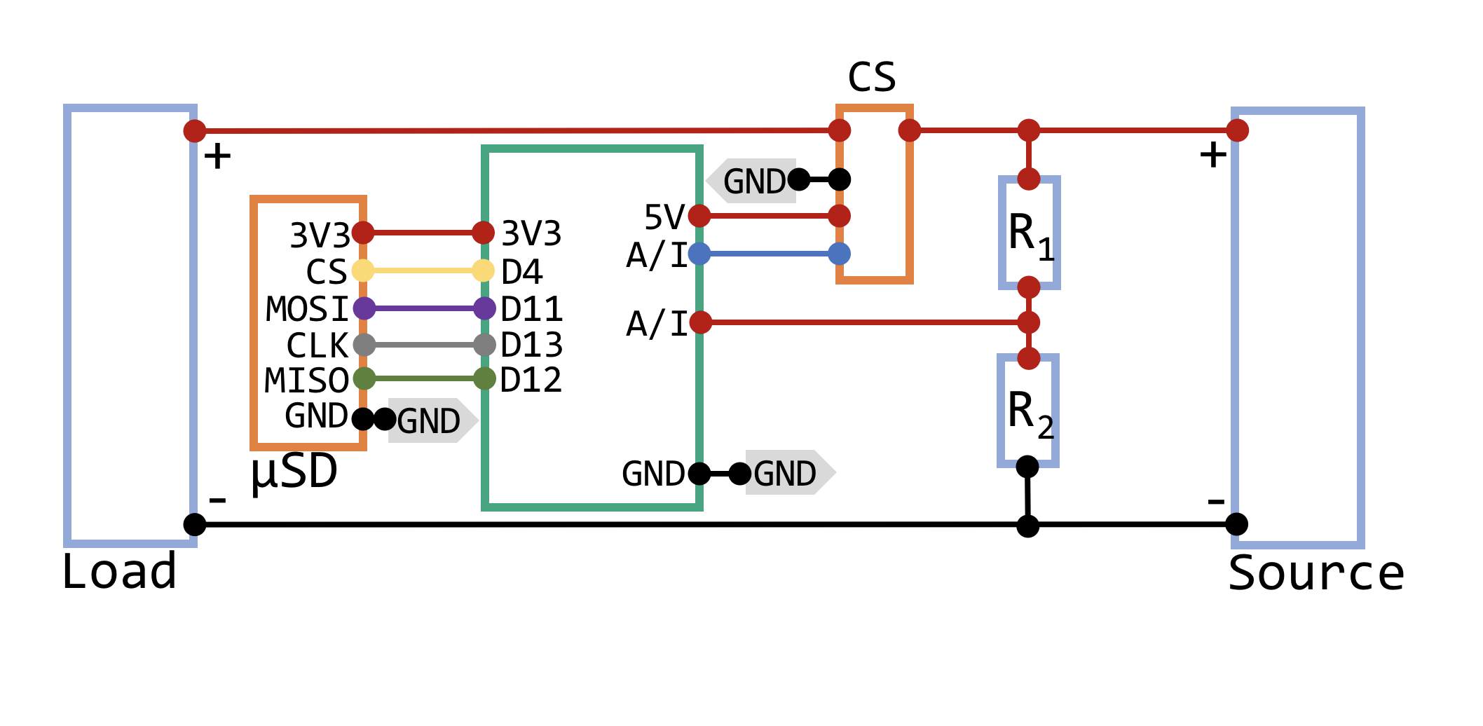
uSD CARD READER
This is very well documented on Internet, but I will explain what I did. Figure below shows where it is located on the diagram, combined with the voltmeter and the amperemeter:
![]()
I wanted to leave the default layout for the uSD card reader as I believe it would be easier to set it up. It is possible to load a data logger example from the Arduino IDE which I think has all that I was aiming for. I also wanted to add an extra feature in which a new data log will be created each time you go for a ride. I hope you enjoy the code!!
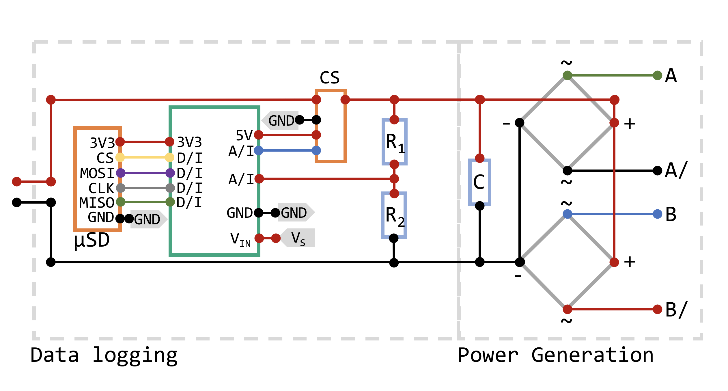
VALIDATION
This is very cool, but let me show you where exactly is located this powerful feature on the main diagram:
![]()
I hope this clarifies all work done so far on the Data Logging and Power Generation stages. I am also assuming that the data logging stage is powered by one of the power banks. I have been using different capacitors (C) for the power generation stage. The best one so far is 100uF@25V.
As you can imagine, using a breadboard you may expect a really big bunch of wires everywhere. My partner (in crime) said that it is like a rainbow!! She is definitely right...
Anyways, let me post a real proof of what I am doing, another video!!
I also managed to export the data and create a nice graph:
![]()
This was right after the video, at home and using my hands to create energy. I did not reach a very high rotational speed but I cannot quantify it as I do not have a speedometer or tachometer.
My sincere apologies to electrobob and Jurist as I mentioned I was generating a max. of 16W (1A @16V). Right now I am generating a max. 6.87W (1.03A@6.63V), which is reasonable. Further tests are coming (and fine tuning of the data logging system)!
All in all, this setup costs around 1/4 of an in hub dynamo setup and I am generating double the power without feeling any drag at all (I cannot prove It yet). I believe all of this is due to the gear system.
Guys, this is turning into something really interesting. Hope I will entertain you on my next stage!
-
Power Generation Stage
06/26/2018 at 23:47 • 2 commentsWelcome to the first stage!
The main aim is to design the system that will generate energy while cycling. Components/tools needed:
- 1 x Stepper Motor (17HS4417). It needs 1.7A (0.85A/phase) @12-48 Vdc
- 1 x JSP XPH-4 male + female + inserts
- 4 x M3 screws
- 1 x Aluminium U channel for the Motor Bracket
- 1 x 3D-printed Spur Gear
- 1 x 3D-printed Pinion Gear
- 6 x M6 stainless steel washer
- 2 x Full-wave rectifier (2W08M)
- 1 x Electrolytic capacitor (25V, 100uF)
- 1 x DC-DC step-down converter (MP2315)
- 1 x M3 Allen Grub Screw
- Calliper or similar for measurements
- Bike - I am currently using my own bike
Nowadays, most of bikes incorporate disc brake systems, so I decided to design a spur gear to be fixed using the same screws as the brake disc and brake callipers. I chose the rear side of the bike as it is easier to modify, so I can fit the motor bracket without adding extra components. However, since I am planning to 3D print first versions, I will not be able to fix all components as tight as it needs to be. 3D printed parts may brake under high pressure.
So, I made some measurements and designed a quick prototype. Measurements depends on what is the size of your brake disc, the available space between the disc and the bike frame, and the size of the selected stepper motor.
I will use ANSI metric standard to design the gear system. In other words, both gears must have the same modulus (M), which is the selected circle pitch diameter (D) over the number of teeth (T) (figure below):
In my case I manage to obtain a gear ratio of 4.5 and have some space left so it could theoretically fit smaller break discs as there are many variations.So far, I have been working on the second version. The motor bracket needed extra modifications as it needed to be reinforced with a rib. It also has been printed from one side so the filament direction will not be compromised under oscillations. The spur gear has been thickened compared to the first version and the use of washers was also very helpful.
Figure below shows the previous design (right hand side) and the improved design (left hand side). I still need to go through a third version regarding the motor bracket because the motor shaft was touching the brake disc. I am sure you will notice it on the next picture.
The next step was to assemble all components. It still needs some minor modifications, but it looks promising! As I said, only four extra screws are needed to fix the motor.I tested the system by connecting both phases of the motor in series to a capacitor, then DC/DC step down converter and a generic powerbank at the end.
Do not forget to watch the video! Unfortunately, the first time I had a 50V capacitor instead of a 25V one. I think I do not have to explain what happened to the DC/DC step down converter. However, I could still use it as a 'circuit load', so I managed to check how much current was generated. The multimeter is connected as an Ampmeter (series) after the capacitor, so as far as I know it should show the current generated at 25V (units shown are Amperes).As it can be seen, 700mA were easily generated @25Vdc. This seems quite logical for me as each phase of the motor requires 850mA to work (I will update the video as soon as I get more DC to DC converters)
Looking forward to make more tests...on the road!!
UPDATE - 2/7/2018
Yesterday, my partner and me decided to meet some friends in London. I could not see a better chance to test what I have been working on for the last few days. Well, I did not have anything installed on the bike but the motor and gears, so I opted for a quick solution by designing a PCB and putting altogether in a plastic box.
I know, I know...the box looks ugly and bulky...buuuut it is a quick and efficient solution. As you may see in the second picture, I checked the battery level on the power bank by plugging in my phone. It was dead as nothing was displayed on the screen.
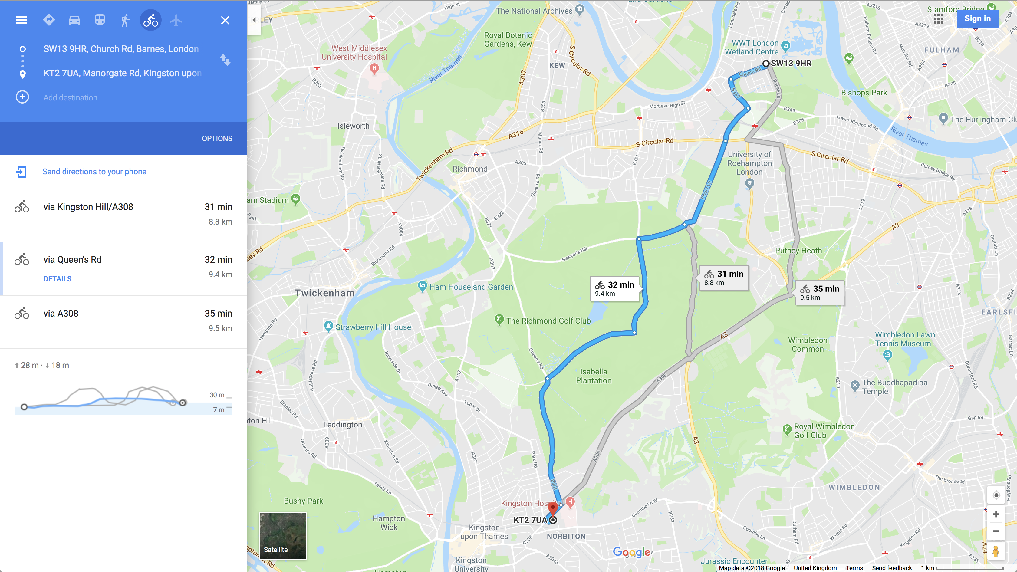
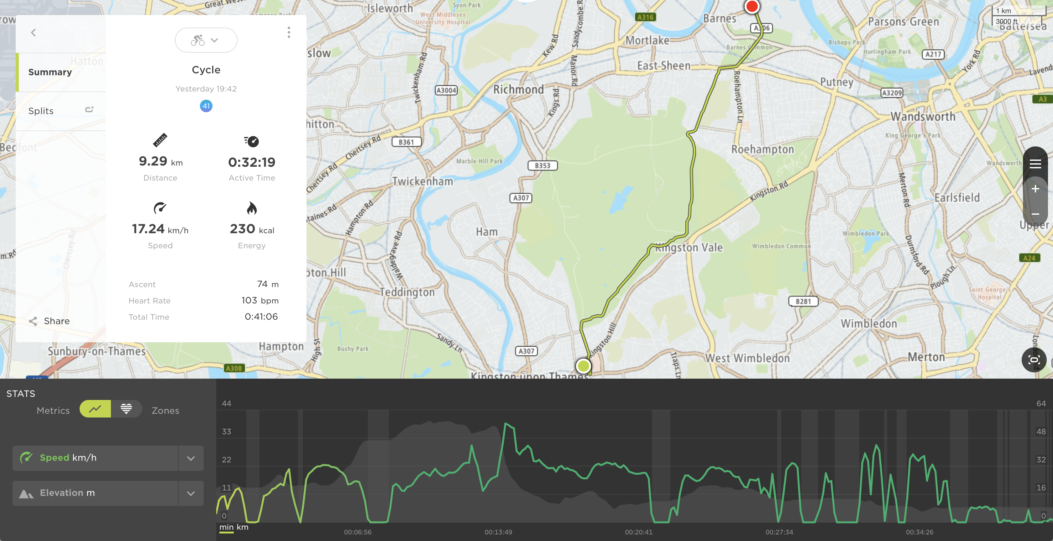
Now, let me show you the bike route. First picture is Google Maps estimations and second picture is what my TomTom Runner measured. I cannot show any data regarding the energy generated as I am still working on the datalogging system.
![]()
![]()
As it can be seen, I stopped several times to check that everything was working fine and we covered a total of 9.29 Km (one way) with an average speed of 17.24 Km/h. Having in mind that I had to come back, the total trip is around 20 Km in around 1 h. I made a picture of the power level when I finished and this is what I found:
It looks promising! Now, I need to work out some calculations to validate my results.
Next time, a trip with data logger!!
UPDATE - 6/7/2018
I have been commuting to work (15 min one way) whilst building the data logger system for the bike. Here are my findings having in mind that this is a prototype:
- There is evident tear and wear on 3D-printed parts, so I decided to apply some grease. As a result, no noise due to friction.
- The motor bracket is not stiff enough. Road bumps makes it oscillate (aka fatigue phenomena) and the spur gear tends to touch slightly the braking disc. I have already seen some cracks so I decided to manufacture a proper aluminium bracket.
- The stepper motor makes a very nice sound when it is spinning, like an electric car...the noise of power generation!!
- I tried to push hard these days to test the power generation stage and it gets really hot at high speeds, so I realised from the setup, that some connections were not properly made. In addition, Jurist made me realise that I had diode bridges connected in series (higher voltage) rather than in parallel (higher current). Again, I am still building the data logger system and still cannot upload results, but I was able to generate 1A@16V (16W).
Let's keep pushing hard...
Q&A Section
Can I use different stepper motors?
Yes you can, but bear in mind that your circuits may need to be redesigned and you may also start experiencing some drag if a powerful motor is chosen.
How can I identify phases in a bipolar stepper motor?
Grab a multimeter and switch it to resistance measurement mode. Now take two random cables and measure its resistance. If those cables are part of a coil, they must show a resistance value (value depends on the motor size).
imPulse
Energy harvesting alternative for bikes including data logging, smart lighting system and power distribution board for power banks
 Javier Betancor