-
Exploring optics
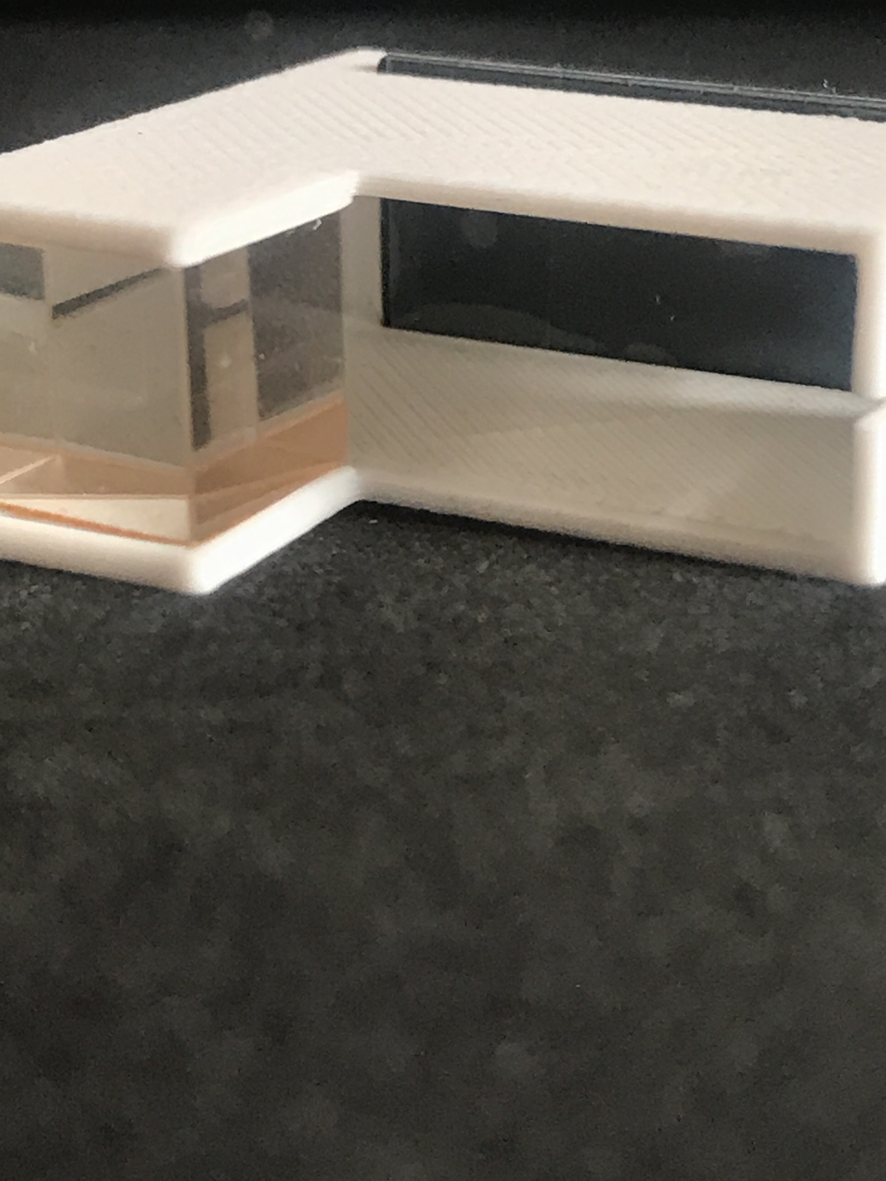
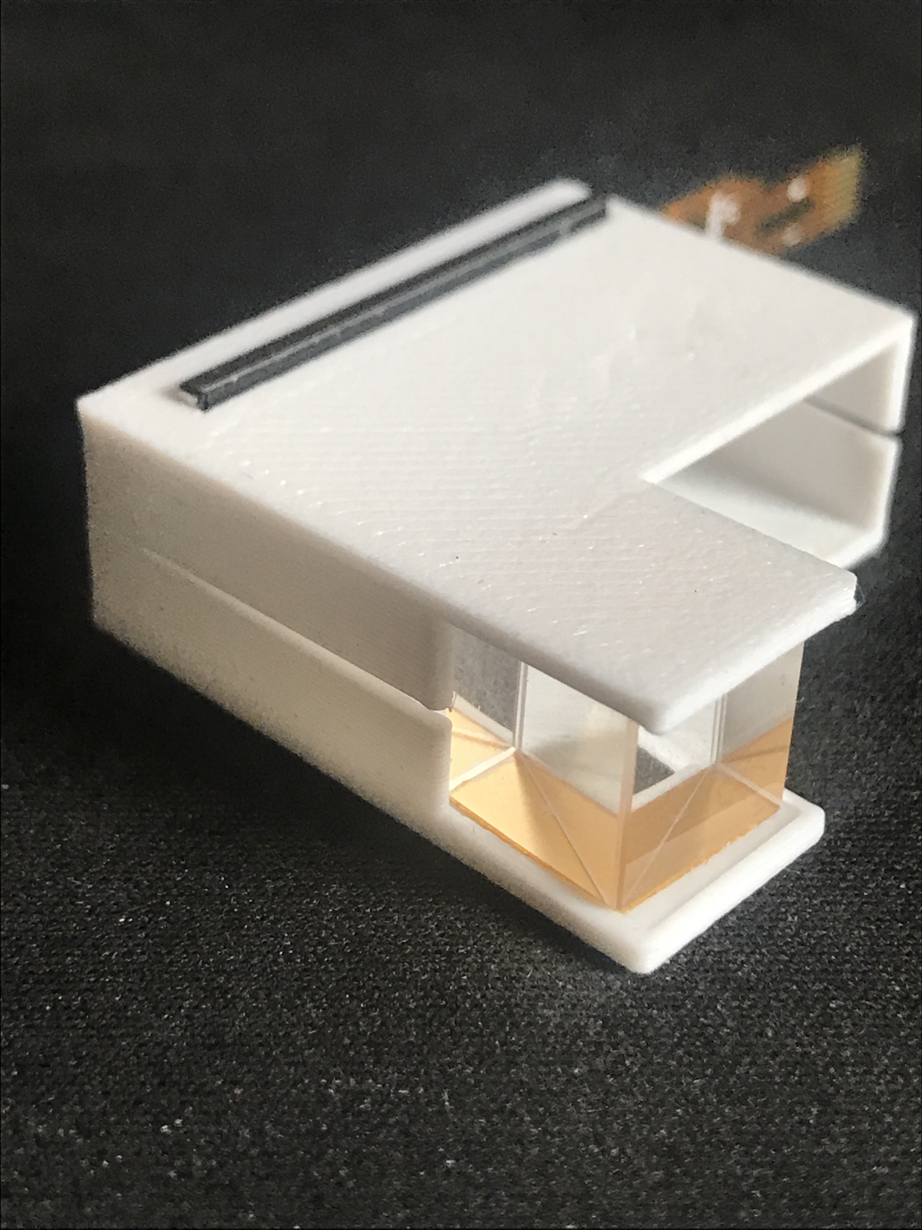
06/30/2020 at 14:24 • 0 commentsI am now trying to test some optics in order to find the most comfortable, most adjustable and most compact layout. I have printed a small case to hold the display and prism however I think I will need a new prism or get a smaller display in order to fit the full image. I have a rough idea on what lens I will need so I also need to buy that but for now I am going to try and make do with my current lens and prism.
This prism is actually two right angle prisms joined together so it forms a cube with a divide in the middle to reflect the image to the eye. -
Modifying code
01/28/2020 at 15:28 • 0 commentsI am struggling with this part of the project - modifying code that connects my ESP32 to my iOS device. I think I need to go back to basics and handle each feature of the code by breaking them down to the bare, essential parts and trying to code those into the sketch. This is by far the longest part of this project but I'm willing to learn.
I really need to buy a 3D printer, outsourcing it is immensely expensive. At least I'll be able to work on the code until I can buy a printer.
-
FPC Adapter
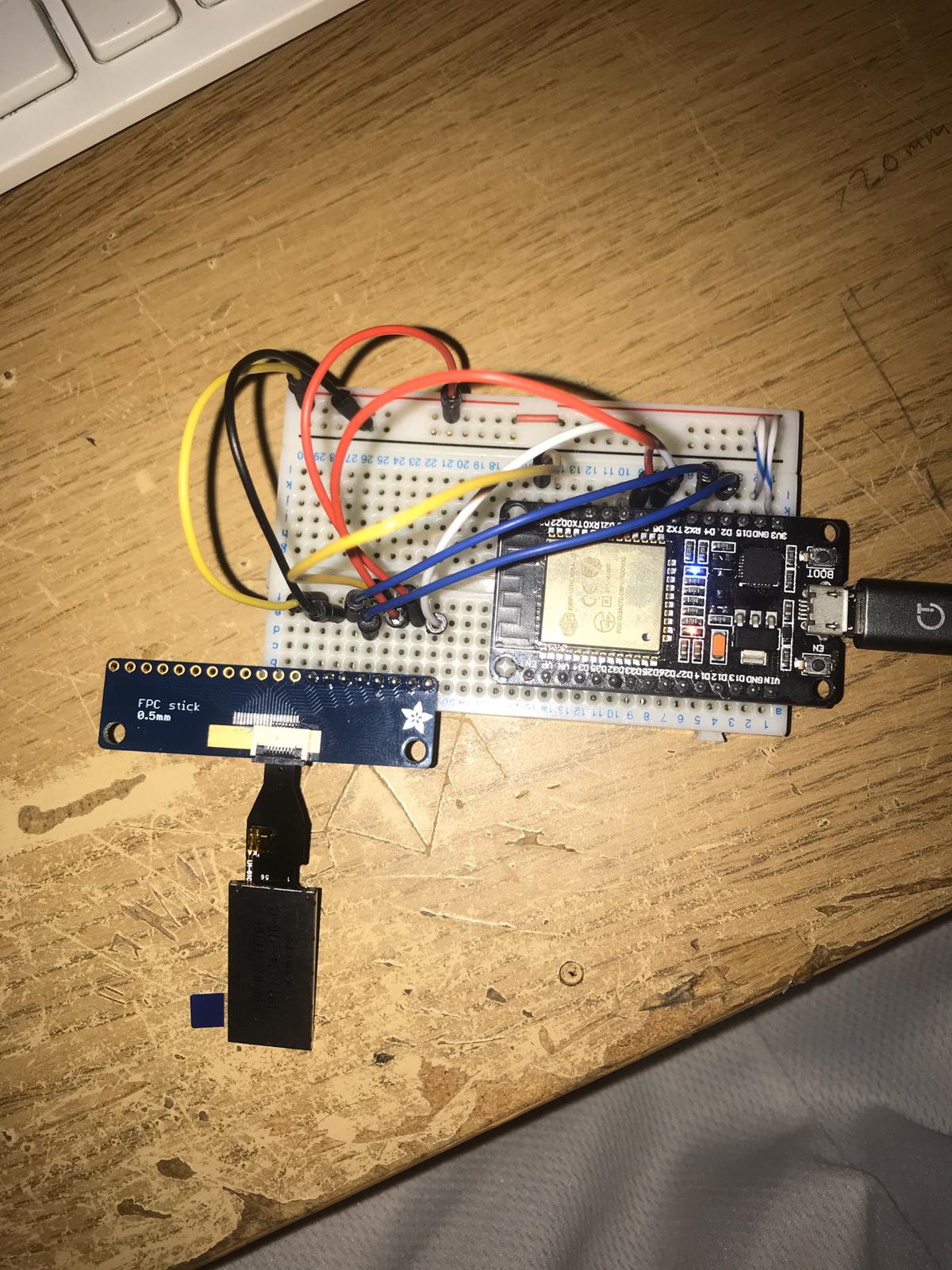
01/23/2020 at 17:58 • 0 commentsFPC to DIP adapter arrived and I went straight to testing my screen. Its not quite DIP but whatever, I got a universal one from Adafruit called "FPC Stick" It has 0.5mm pitch on one side and 1.00mm pitch on the other supporting up to 20 pins on both sides. An adapter with amazing quality though kind of expensive; I needed one quick, no regrets at all though since I'll probably need to use this again and it will last.
I didn't solder the mechanical pads because I don't really need to and makes it easier to remove (I haven't practised using hot air on plastic connectors much and don't want to melt it when I need to remove it)
Adafruit also sell a bigger version: https://github.com/adafruit/Adafruit-FPC-SMT-Adapter-PCBs
Screen works, now I need to design optics
![]()
-
New PCB design
01/19/2020 at 13:56 • 0 comments![]()
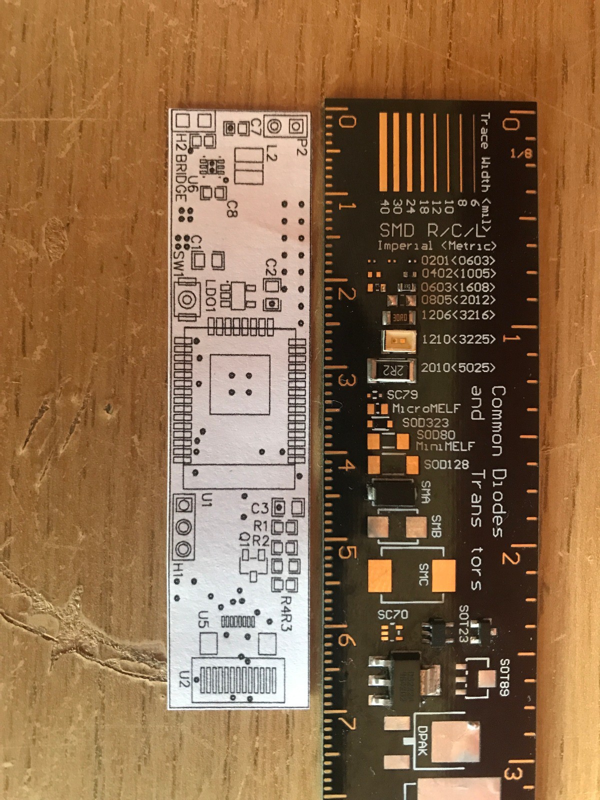
This is a PCB design I've created that lets me integrate the new ESP32 module I bought with the other components like TFT IPS display, battery and power switch. There is a 3v to 5v boost circuit on the PCB and I have designed the PCB to let me use the ENABLE pin on the boost IC with a switch (to turn the chip on and off with the switch) or to keep the ENABLE high all the time with a solder bridge or 0 ohm resistor.
I did this just as an experiment because I was wondering how other complex devices can be controlled by one switch like a laptop which has so many IC's that need to turn on at different times. So this was my opportunity to experiment with it, if it doesn't work I can just pull the EN pin high with resistor.
I also have an LDO regulator there because I'm not sure if the boost circuit will even work, If it doesn't I can cut the traces and solder the battery straight to the LDO inputs and job done. Also most importantly the ESP32 needs 3.3v to operate with a suggested minimum output current of 500mA which this chip certainly does have.
On the far right, you can see pads for an FFC/FPC connector and another array of pads to the right of it. This is so that the PCB can let me use both kinds of my display. There is one type with an 8 pin 0.5mm pitch FFC and another which is meant to be soldered to a board with 13 pins at a pitch of 0.7mm I think (I couldn't find any connectors with this pitch either). The bank of capacitors, resistors and transistor between U1 and U5 are those components that you see on the back of every display module out there. I just looked at the datasheet for the display and drew a schematic of the display module using continuity mode on my multimeter in order to see how exactly it was all connected.
Next up, I have a FPC connector to DIP adapter board coming, this will let me test my new displays without the blue driver board and see if they work with my ESP32. Then I can move on to altering the code I found online to start displaying messages on the screen.
-
New optics
01/18/2020 at 21:15 • 0 commentsScrapping the current optic design - having trouble with being able to keep the display close to my eye but also having the image in focus. I am trying out an optic layout very similar to Google Glass as the path that the light travels is visually smaller (so it can be close to my eye) but actually allows the light to travel probably double the distance. This means I can use a higher focal length lens therefore reducing the chromatic aberration since the image will now be in colour (I hope) and not monochrome like the old one.
-
ANCS and ESP32
01/18/2020 at 21:01 • 1 commentI have started work on getting my esp32 module connected to the iOS ANCS service. ANCS is a bluetooth service that essentially relays any notifications that appear on the iPhone to the device connected via Bluetooth/BLE. It's quite difficult because I for one, don't really know how to do this bluetooth stuff and secondly, iOS has quite a complex connection method in order to properly bond. If done correctly I won't even need an app for this device, my mind was blown to be honest, I've been trying to find a good app builder since I started this project.
There are codes ready to use online, however I lack proper knowledge on how to use these examples so I need to learn all this first.
This project has progressed so much and will continue to do so. I am willing to help anyone with a similar project so leave a comment or message :)
-
V2 - because why not
11/30/2019 at 13:05 • 0 commentsThis is a new version of the housing since I found a smaller version of the esp32 called the micro32. This version will be hugely slimmer than the last and hopefully better in every way. Can anyone suggest android app development programs? specifically one that can send notifications from the phone to the esp32.
-
New OLED display holder
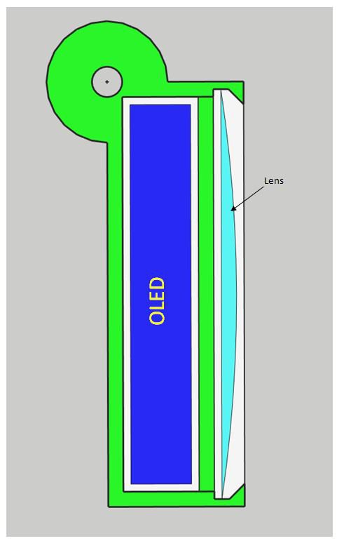
02/01/2019 at 14:05 • 0 commentsThis is the new screen holder that will hold the lens at the correct distance away from the display. The thickness of the green space between the two components is subject to change but if it gets too thick it will add weight and look odd since my goal is to make it look slim compared to other projects like this
-
Current version - almost finished
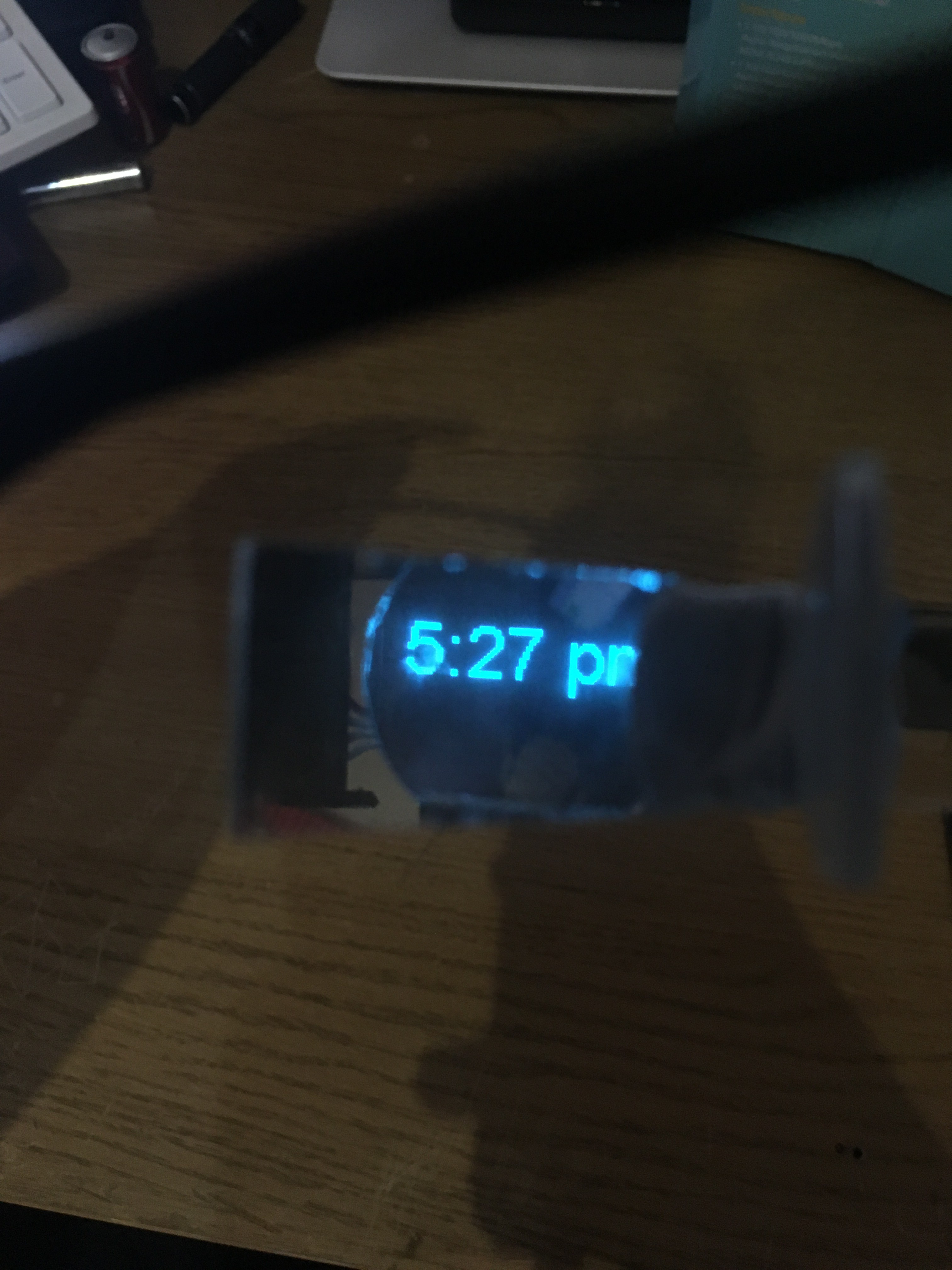
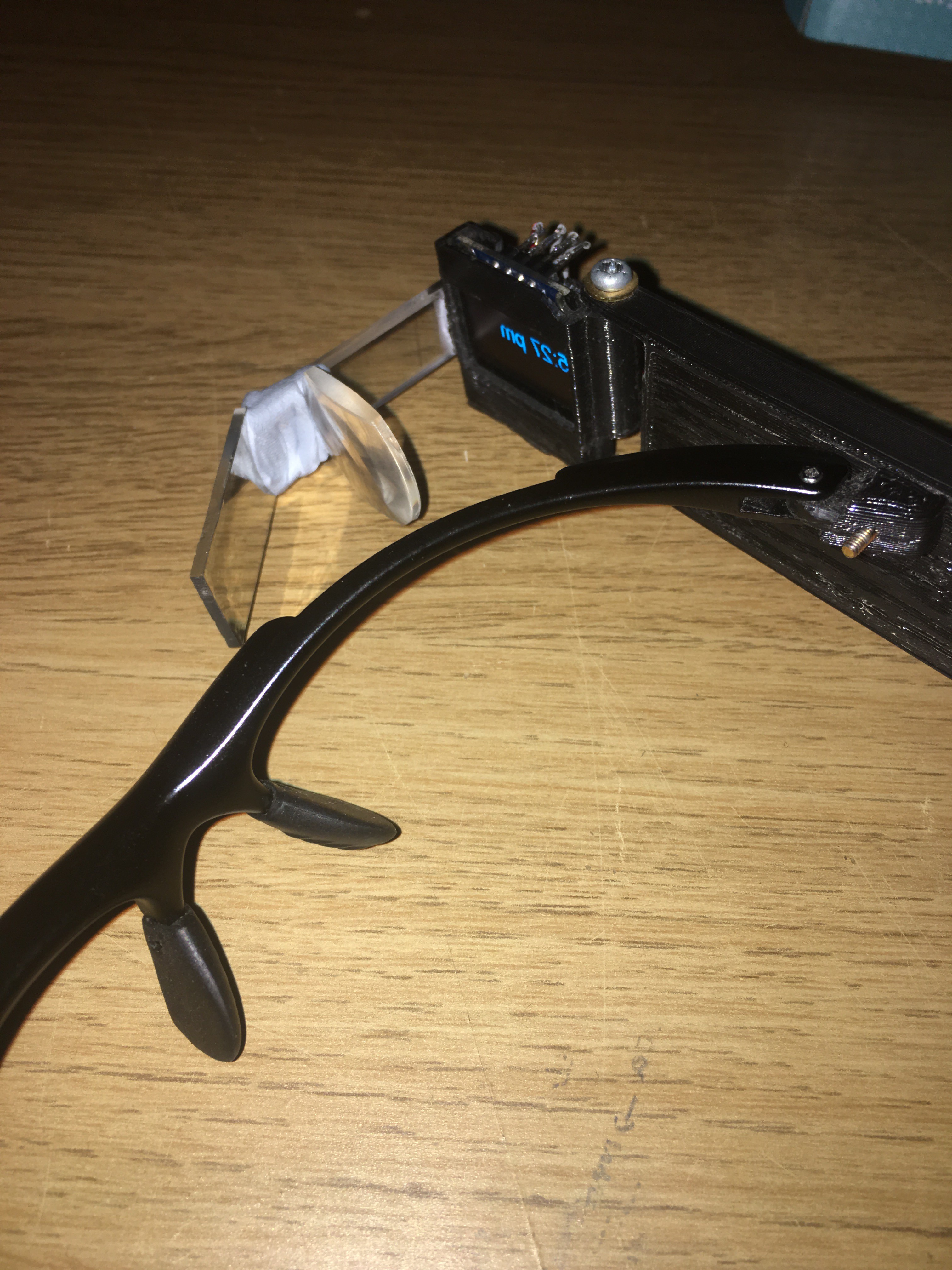
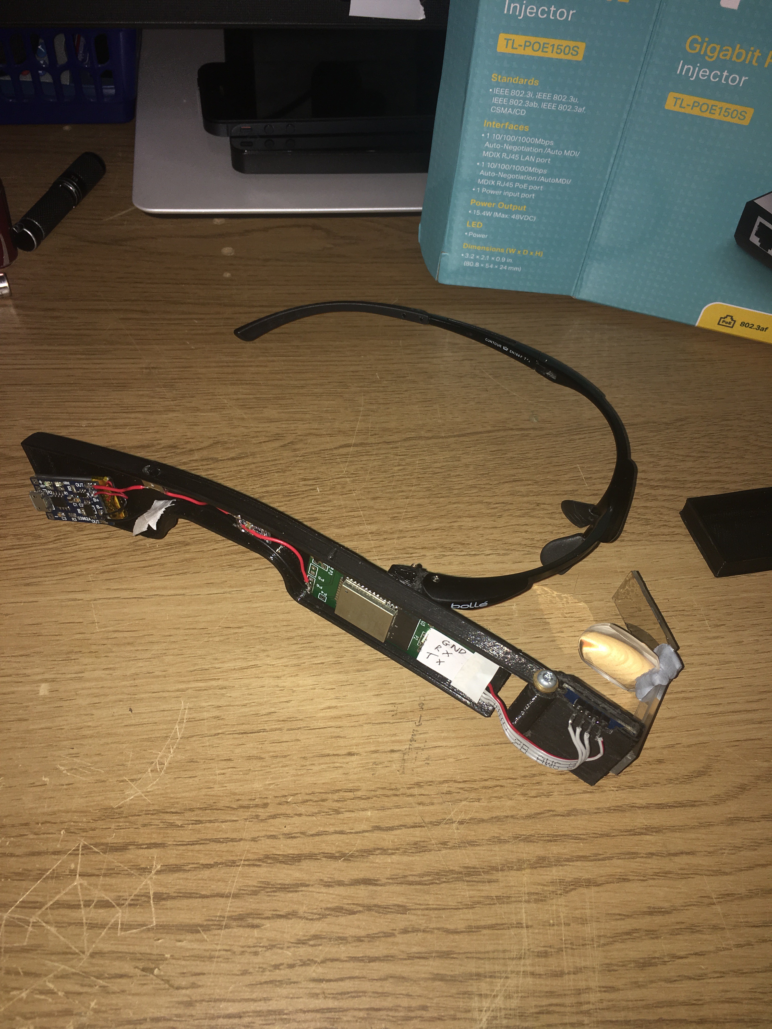
01/29/2019 at 17:38 • 0 commentsHeres an update on how the project is going so far, really close to finishing. Just need to find a lens that will let me mount it as close as possible to the oled display but still keep the image in focus, then I need to make a mount that will hold the screen, lens and reflector as one piece. Bluetack and acrylic were used to allow the current lens to focus into my eye for testing.
![]()
![]()
![]()
![]()
-
Installing components onto the body
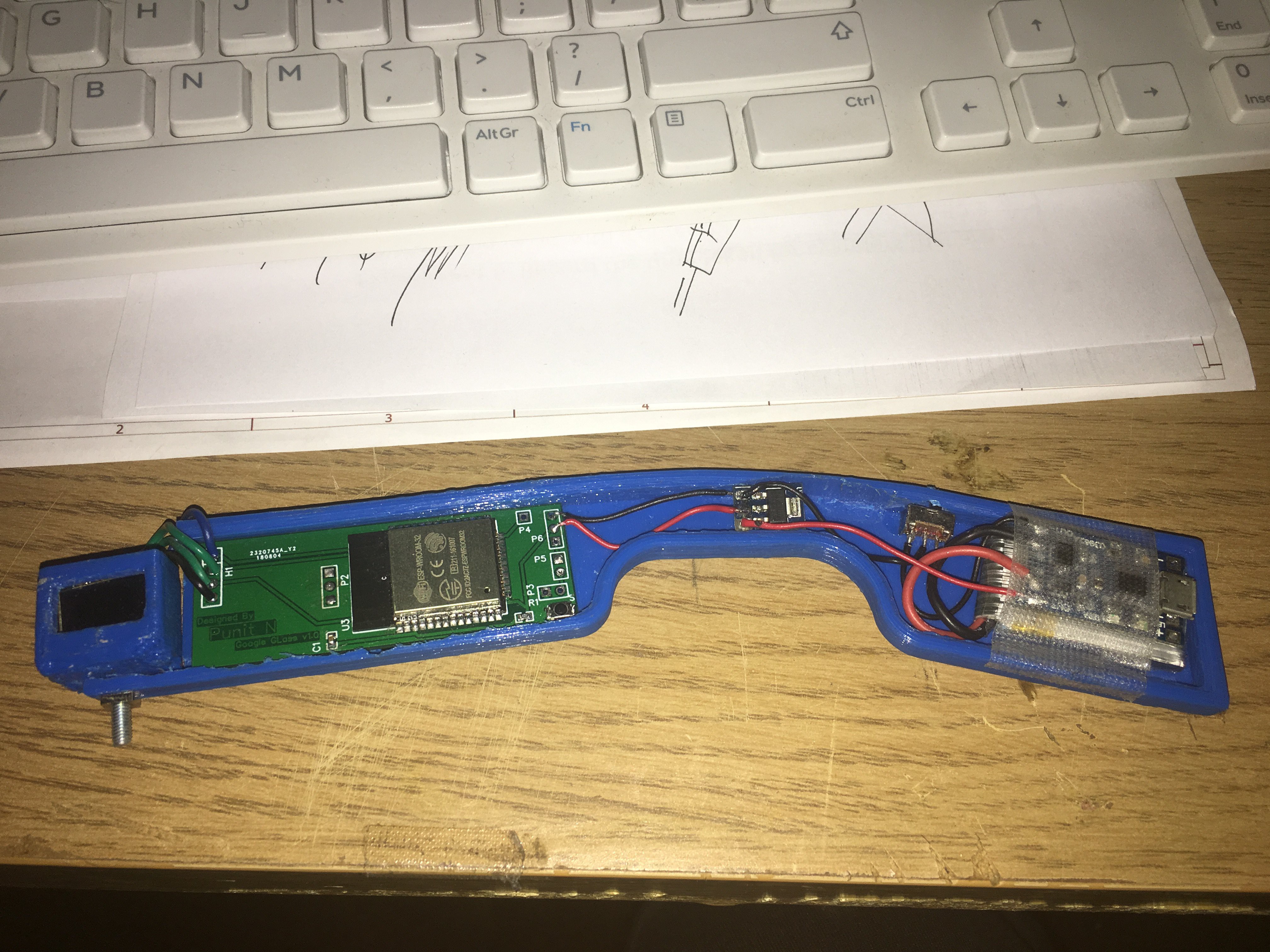
08/30/2018 at 11:22 • 0 commentsDone with installing the main components, the walls of the 3D print were too thick so I used a rotary tool to carve some space out for the custom PCB that holds the ESP32, Boot button and space for headers to connect the serial converter. next is to play around with the optics and get the software running.
