Jonathan Bumstead
-
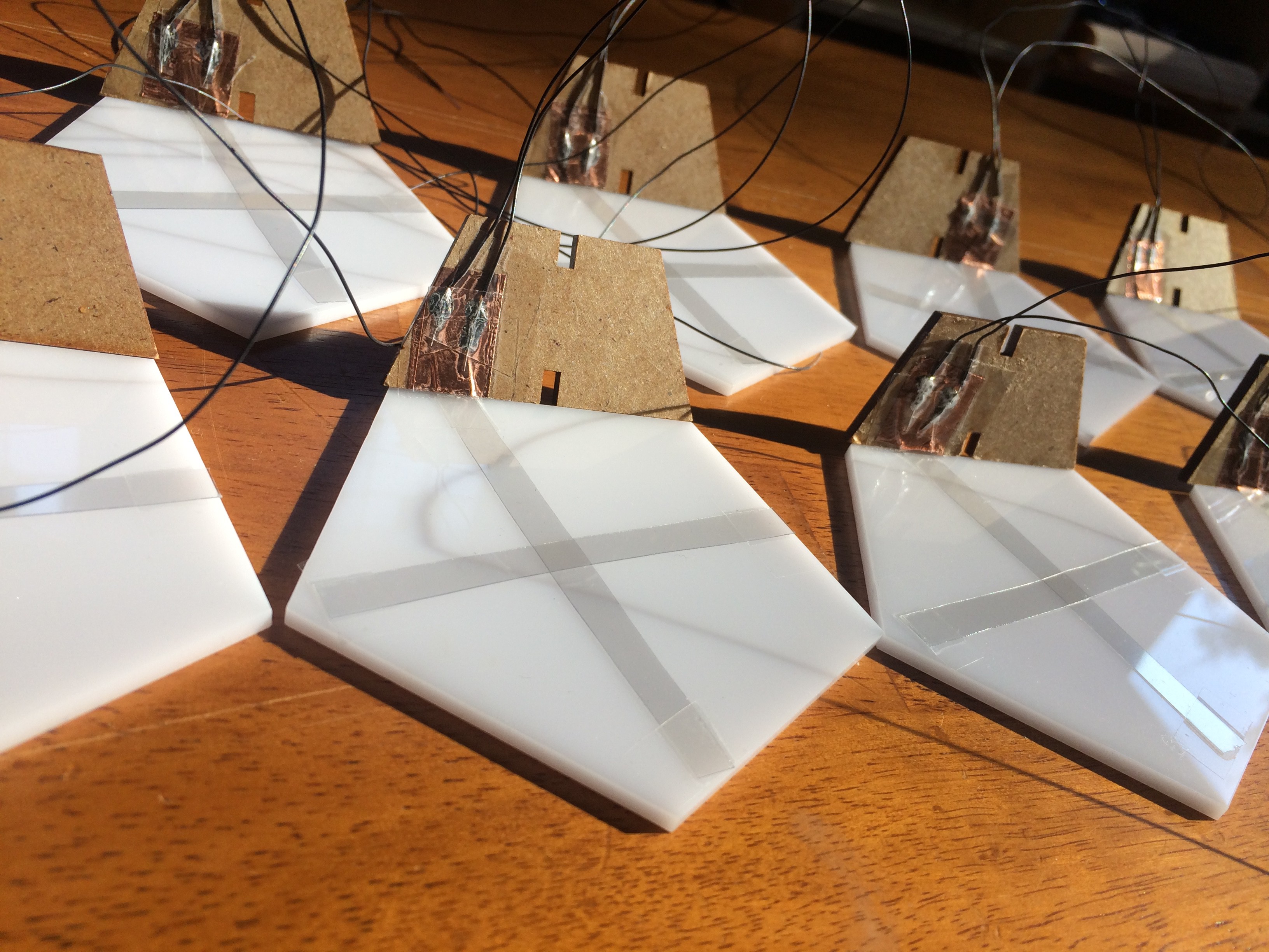
Prototype with capacitive touch keys
10/08/2018 at 03:50 • 0 commentsHere is my first attempt for using capacitive touch keys with the Bucky Glow. The challenge again is finding a transparent material that is conductive (usually copper sheets are used for these types of sensors. First I cut the ITO coated plastic into strips and taped them onto the plexiglass. An edge of the ITO plastic was connected to a copper sheet that was taped onto a wall of the Bucky Glow. The copper is required to soldering wires to the ITO plastic. NOTE: do NOT bend the ITO plastic or it will no longer be conductive. I made this mistake and it took a while to figure it out.
![]()
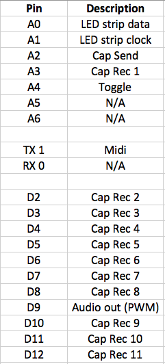
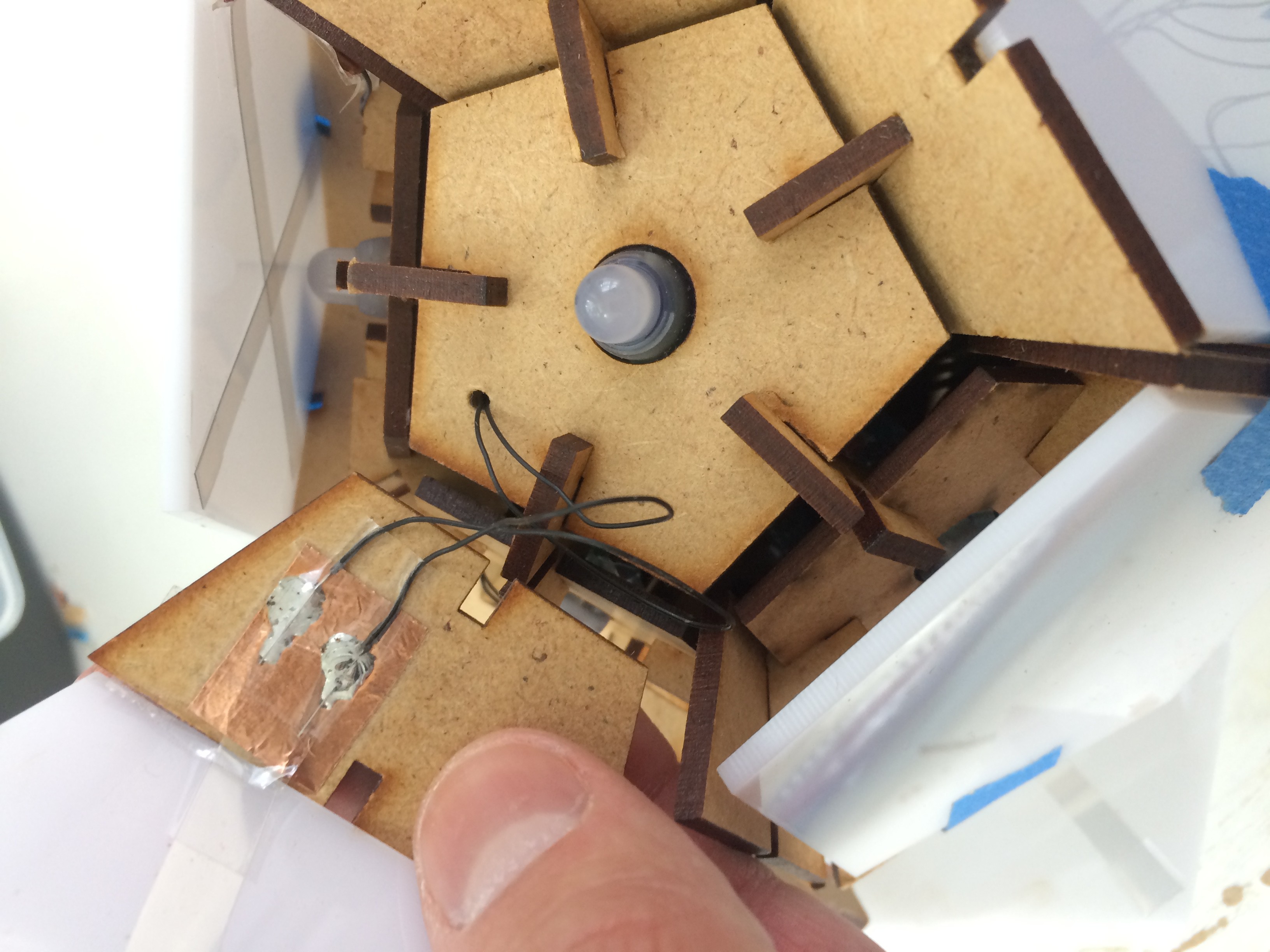
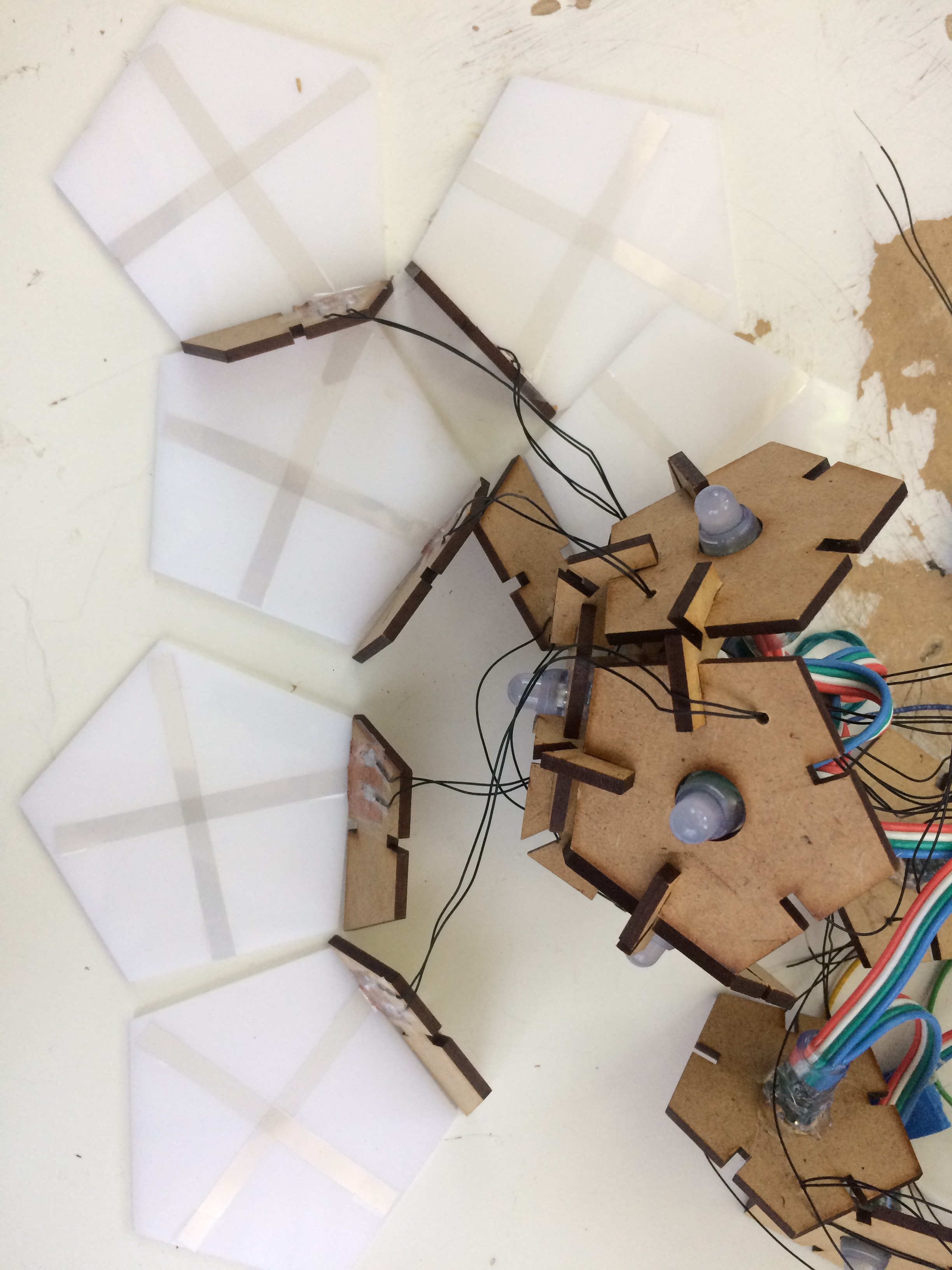
After completing all 11 plexiglass ITO keys, I assembled a Bucky Glow with cables from the capacitive touch sensors running down through the Bucky Glow to the Arduino. Here is the pin layout of this prototype:
![]()
![]()
![]()
And here is the video of the resulting capacitive touch faces for the musical instrument!
-
Audio and MIDI output
10/08/2018 at 03:30 • 0 commentsOne goal I have for the Bucky Glow is to produce both audio and MIDI signals. I recently read this article on producing more complex sounds with Arduino. It works great! However, it is still a challenge to produce high quality sounds quickly. The more complex the audio signal, the more frequency components required and the longer it takes to update the signal.
I set up capacitive touch sensors and a toggle switch to flip between audio and MIDI signals. I used my favorite MIDI library and this great article on Arduino and audio signals. Next step is to produce better sounding audio signals that are fast enough to couple with an instrument.
-
ITO (Indium Tin Oxide) Coated PET Plastic – Capacitive touch may be possible!
10/02/2018 at 04:20 • 0 commentsAfter failures with the contacts in my push buttons, I returned to the idea of using capacitive touch sensors. What is the challenge? I need something conductive right under the plexiglass that doesn't block the light from the LEDs. Today I think I may have found the solution: ITO (Indium Tin Oxide) Coated PET Plastic. ITO coated plastic is conductive AND transparent! So my idea is to place this under the plexiglass and run wires down to the Arduino for capacitive touch. I hope that this is the final solution for turning the pentagons into keys for the instrument.
![ITO (Indium Tin Oxide) Coated PET Plastic - 100mm x 200mm]()
-
Pentagon switch button prototypes
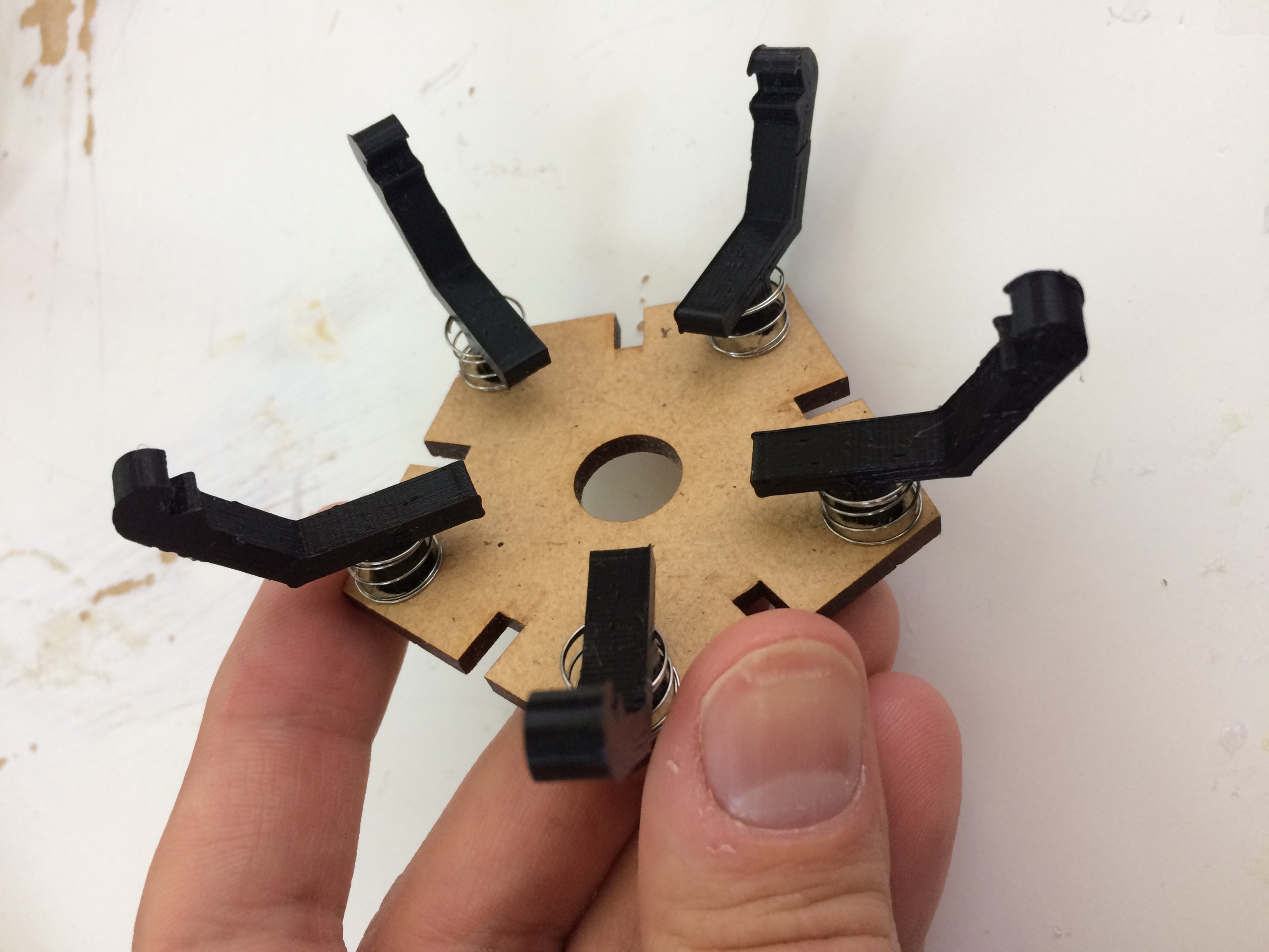
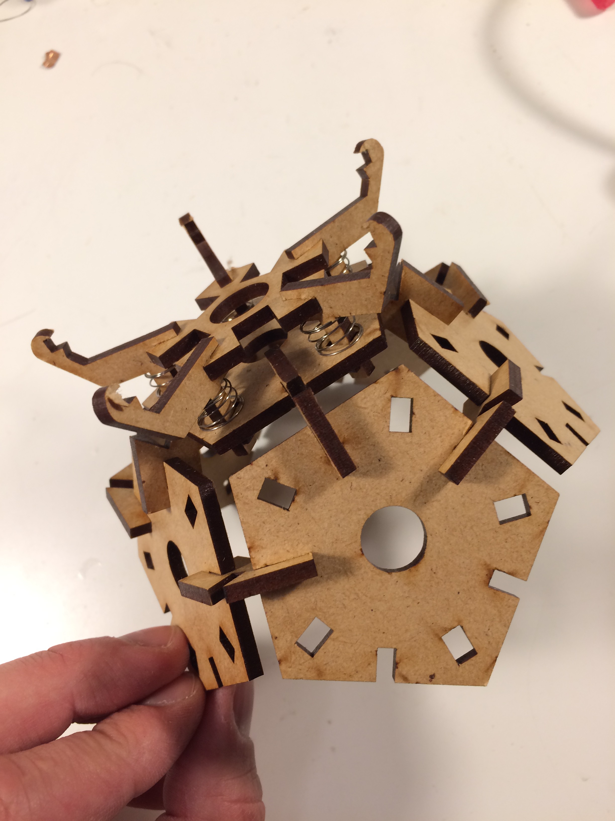
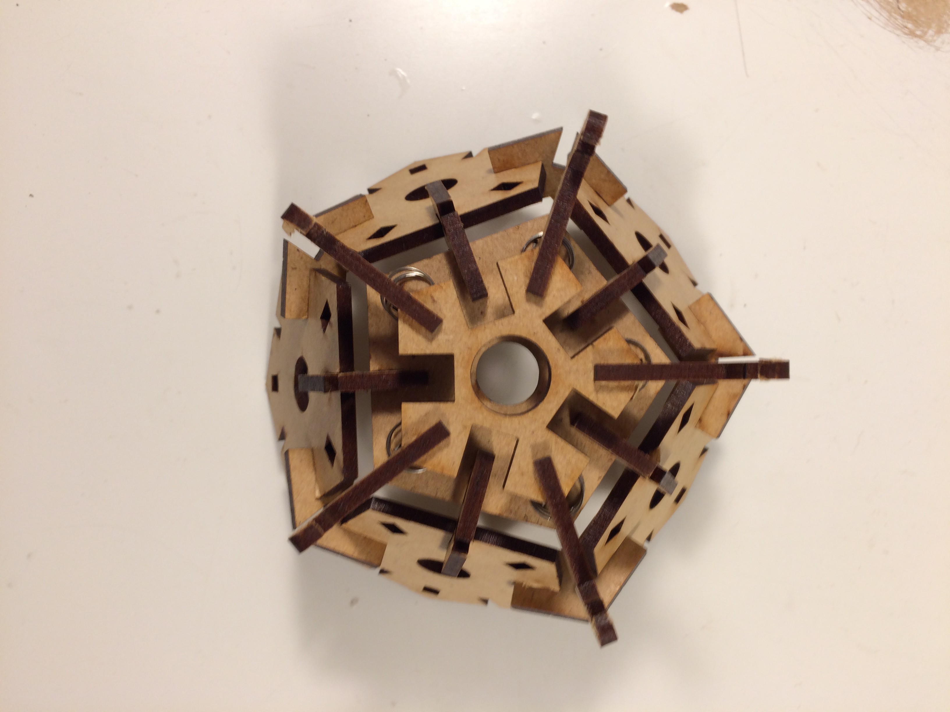
10/02/2018 at 04:14 • 0 commentsHere are a few prototypes for the pentagon switch design I showed in previous logs. After making the first prototype, I realized I needed some better supports for the center. I just glued together the arms uses some old prototype board I had. After checking that this worked, I laser cut a new prototype with a center connector piece.
![]()
![]()
The prototype board was added to support the legs. ![]()
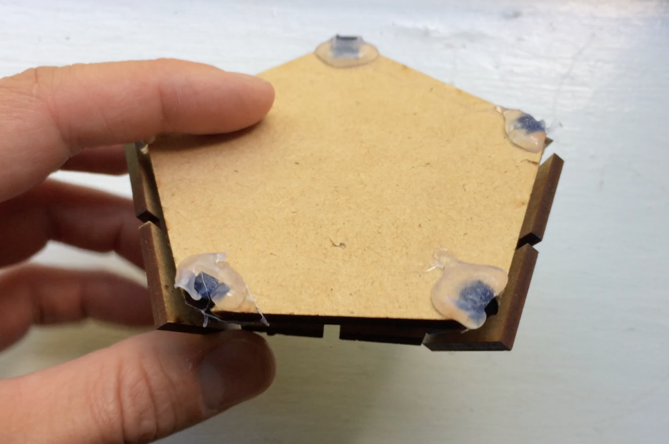
Here I have a MDF pentagon functioning as a substitute for the plexiglass. ![]()
![]()
The spring action is working great, but now I have issues with the electrical contact! I thought the electrical switch would be more dependable, but it turns out that it is sensitive and sometimes does not return to contact when the button is pressed. Most of the problem is due to the mechanical design. Now I am not so convinced that these push buttons are the way to go.
-
Frequency-encoded IR sensors
09/23/2018 at 20:02 • 0 commentsAs a final attempt for IR sensors in the Bucky Glow, I designed frequency encoded sensors. The idea is that the IR emitter blinks at a specific frequency and the detector has a bandpass filter centered around that frequency. This way the detector is only sensitive to the IR radiation emitted from the sensor, not the surrounding IR radiation (unless by chance there is IR radiation emitted at the bandpass frequency).
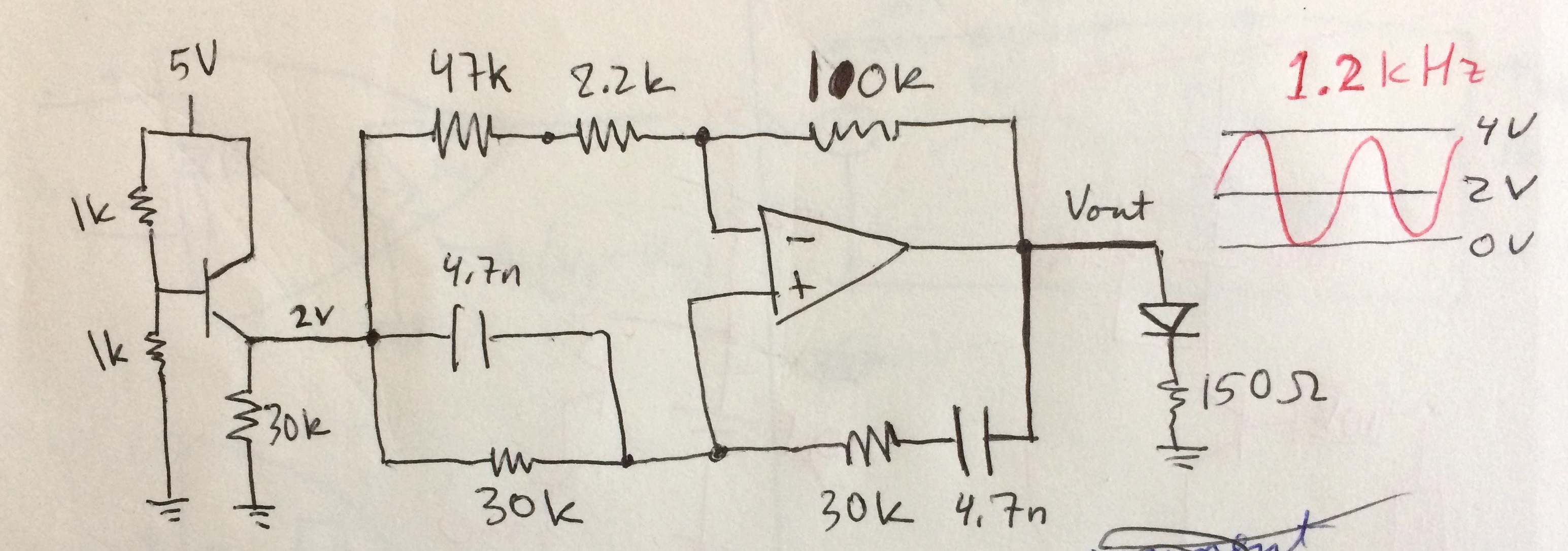
Shown below is a block design for the oscillator and bandpass filter. The signal driving the IR emitter is from a Wien bridge oscillator circuit at 1.2kHz.
![]()
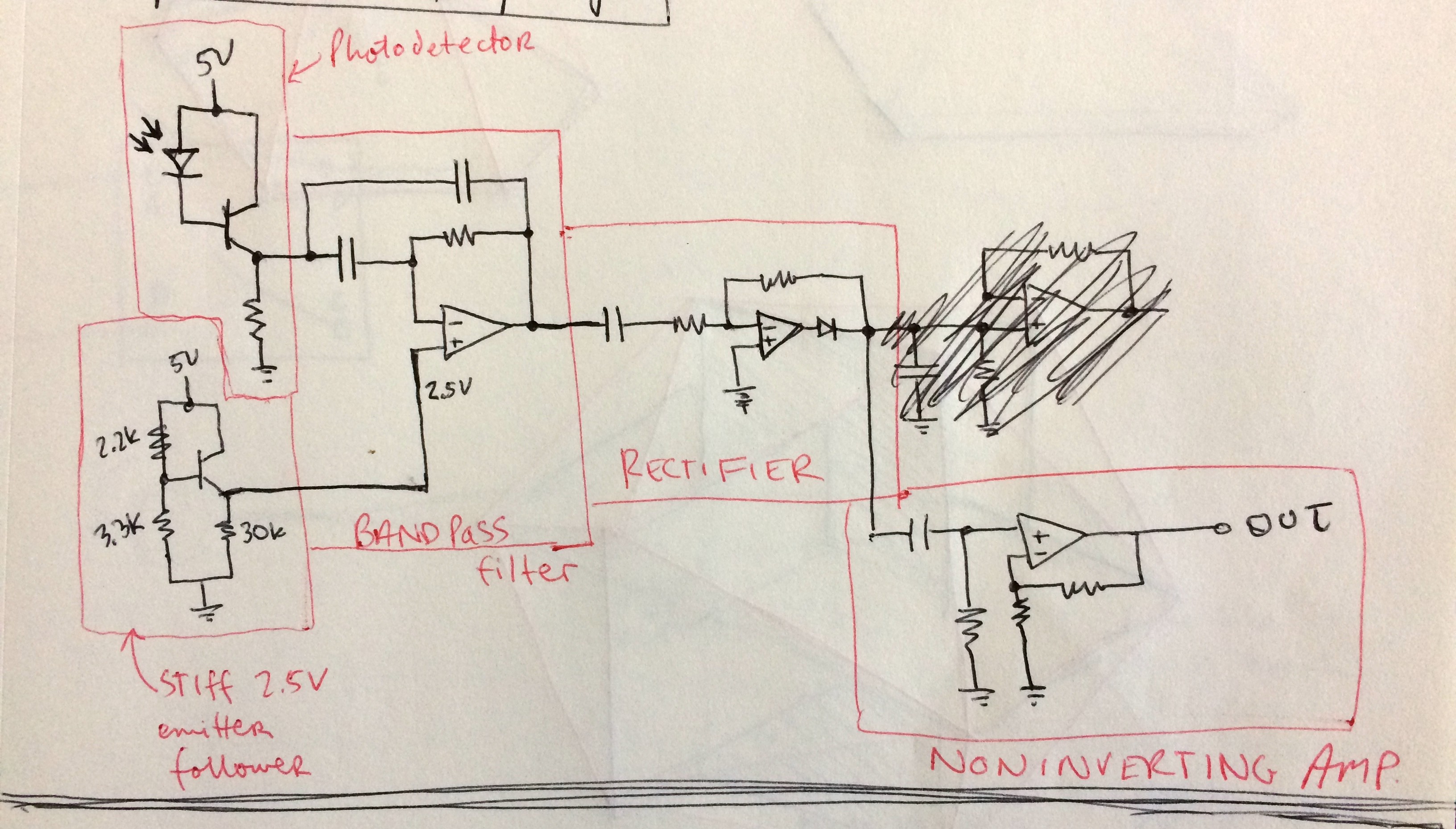
All op amps in the circuit operate at 0 to 5V because I want the board to all run on the same supply. After the photodetector is a simple bandpass filter centered around 1.2kHz. The signal is then rectified because the goal is to have a HIGH signal what the detector is blocked and LOW when it is not blocked. Without rectifying and smoothing the signal after the bandpass filter, then the output would be oscillatory.
![]()
![]()
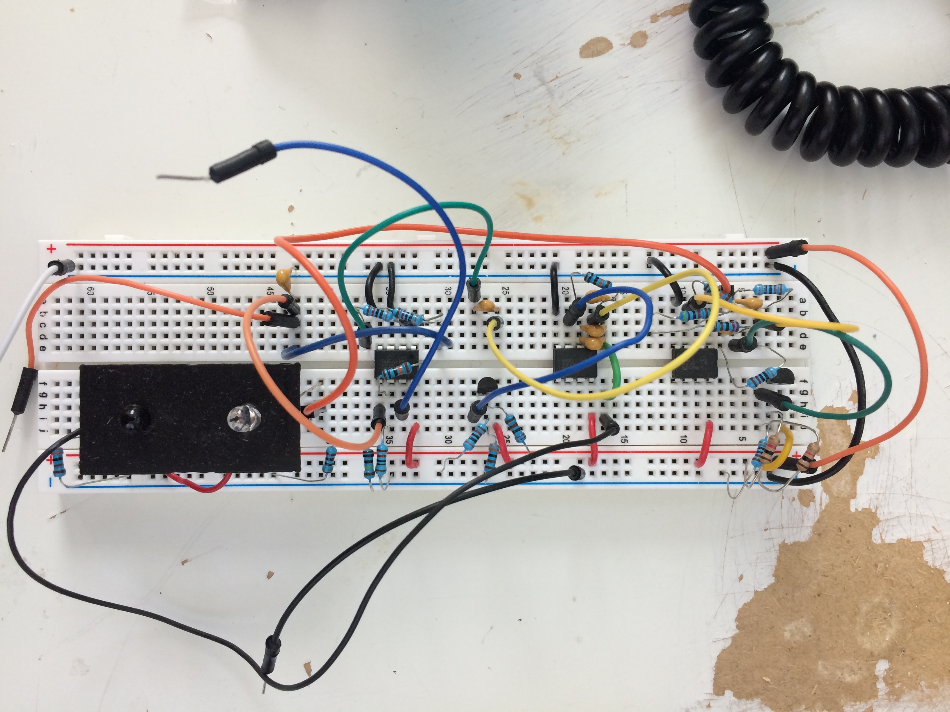
These circuits are working pretty well, but there are again a few issues. First, this design doesn't help with the IR radiation being attenuated by the plexiglass. Second, these circuits will take a lot of time to solder, and I need one for each sensor. For these reasons, I have been moving to a mechanical pentagon switch for the Bucky Glow.
-
IR switches - FAIL
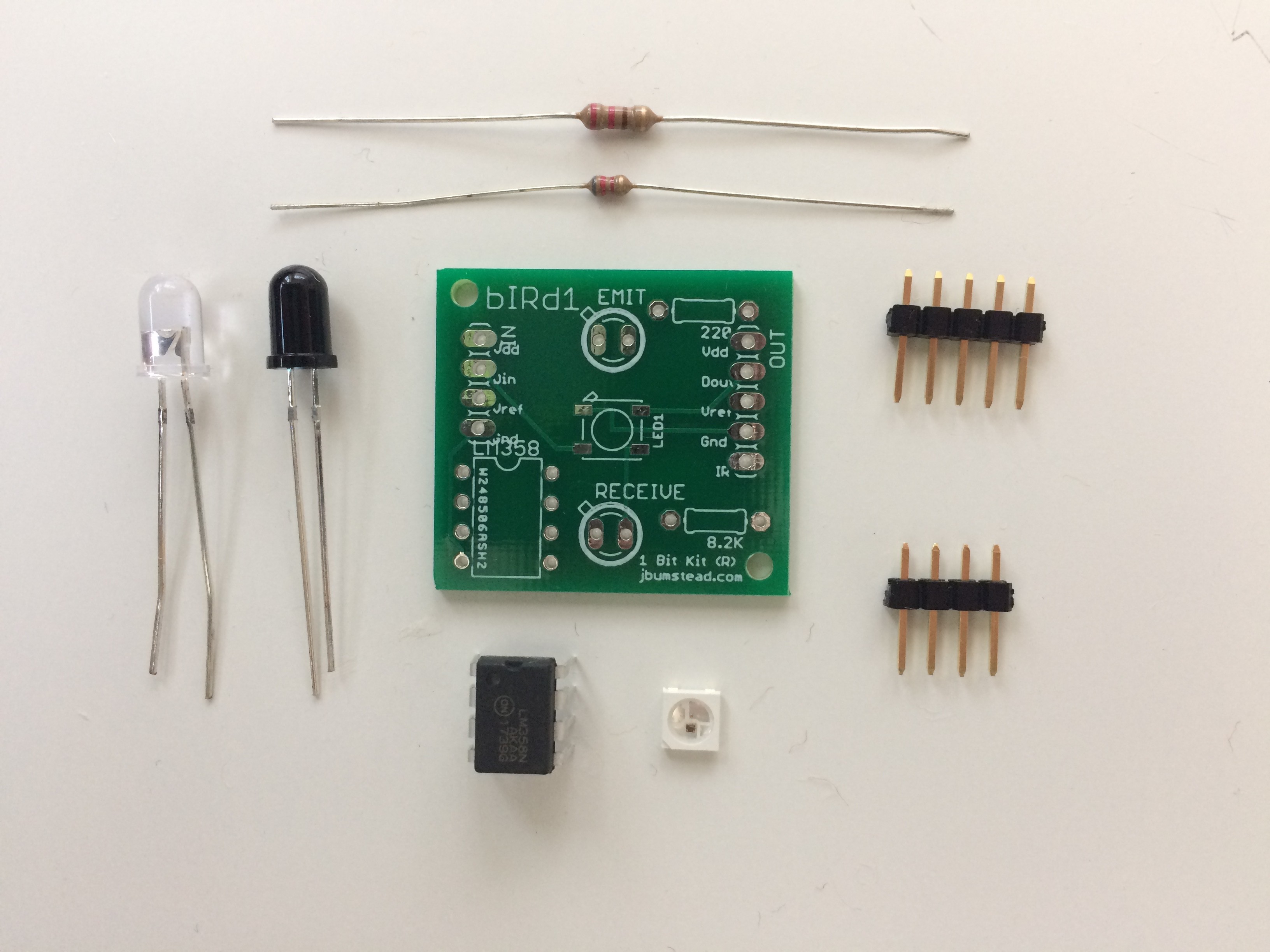
09/23/2018 at 18:04 • 0 commentsOne idea for making the pentagonal faces into switches was to use IR sensors like in my previous large musical geodesic dome. In that project, the IR sensors are above the diffusers. For the Bucky Glow, I wanted the IR sensors to be underneath the plexiglass. The idea was that enough IR radiation would pass through the plexiglass to be detected.
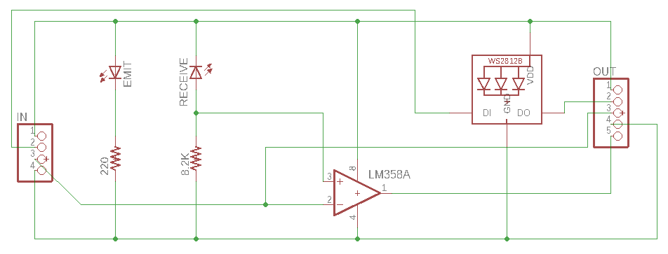
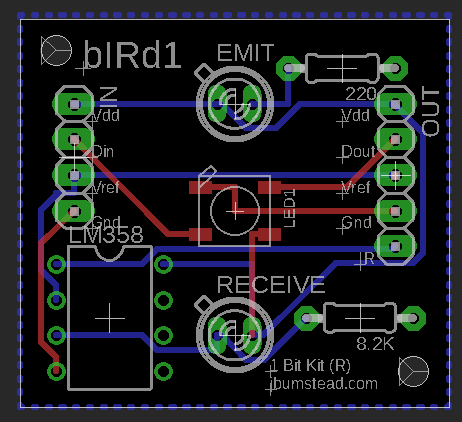
I designed the IR sensor circuit to be incorporated in the same PCB as the LED for the face. The output of the receiver portion of the IR sensor goes to a comparator with a reference voltage provided by an input pin on the board. I wanted to eliminate the need to "tune" each IR sensor like the dome, so every board would have the same reference voltage (which could be adjusted depending on the situation.
![]()
![]()
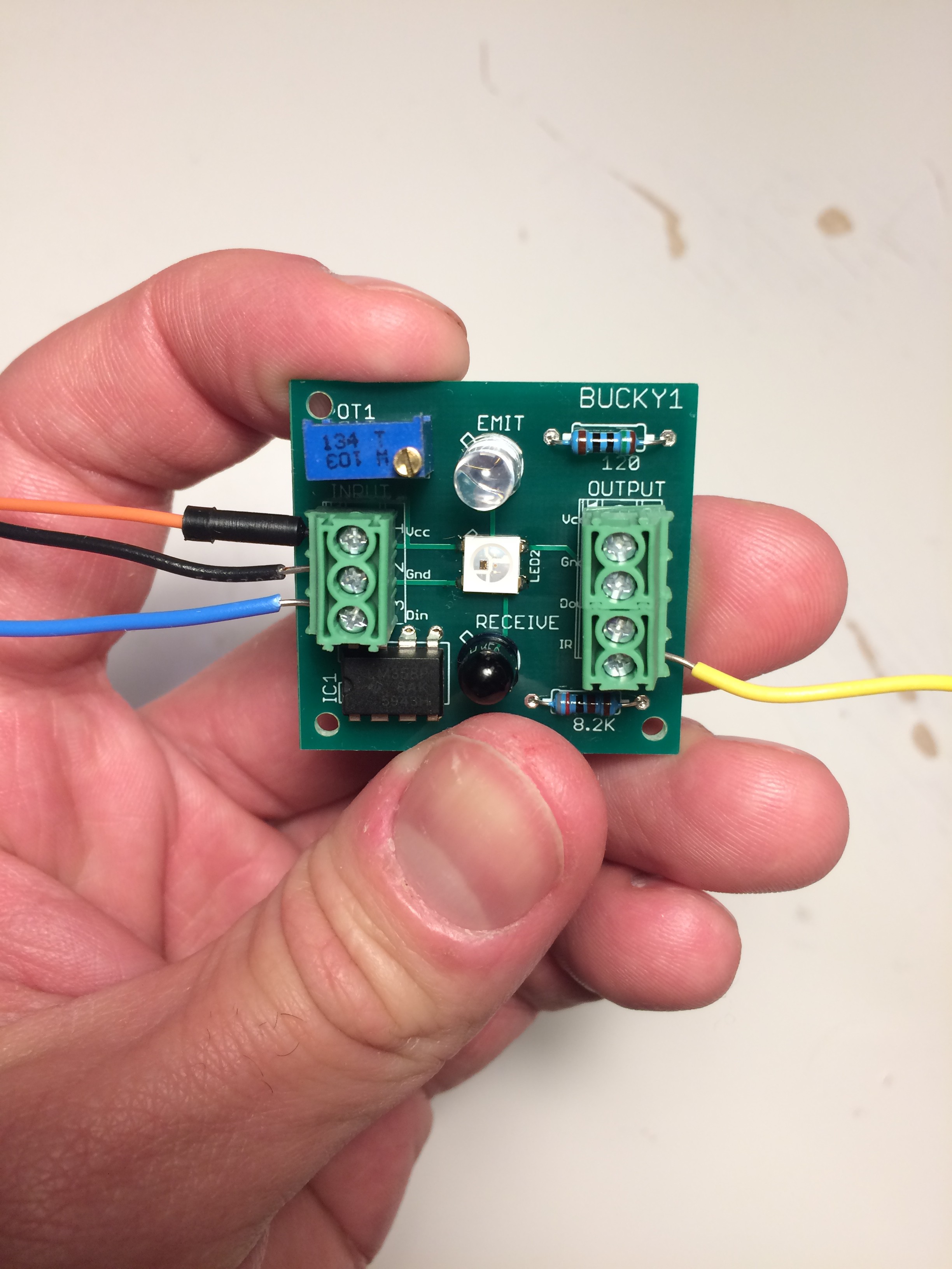
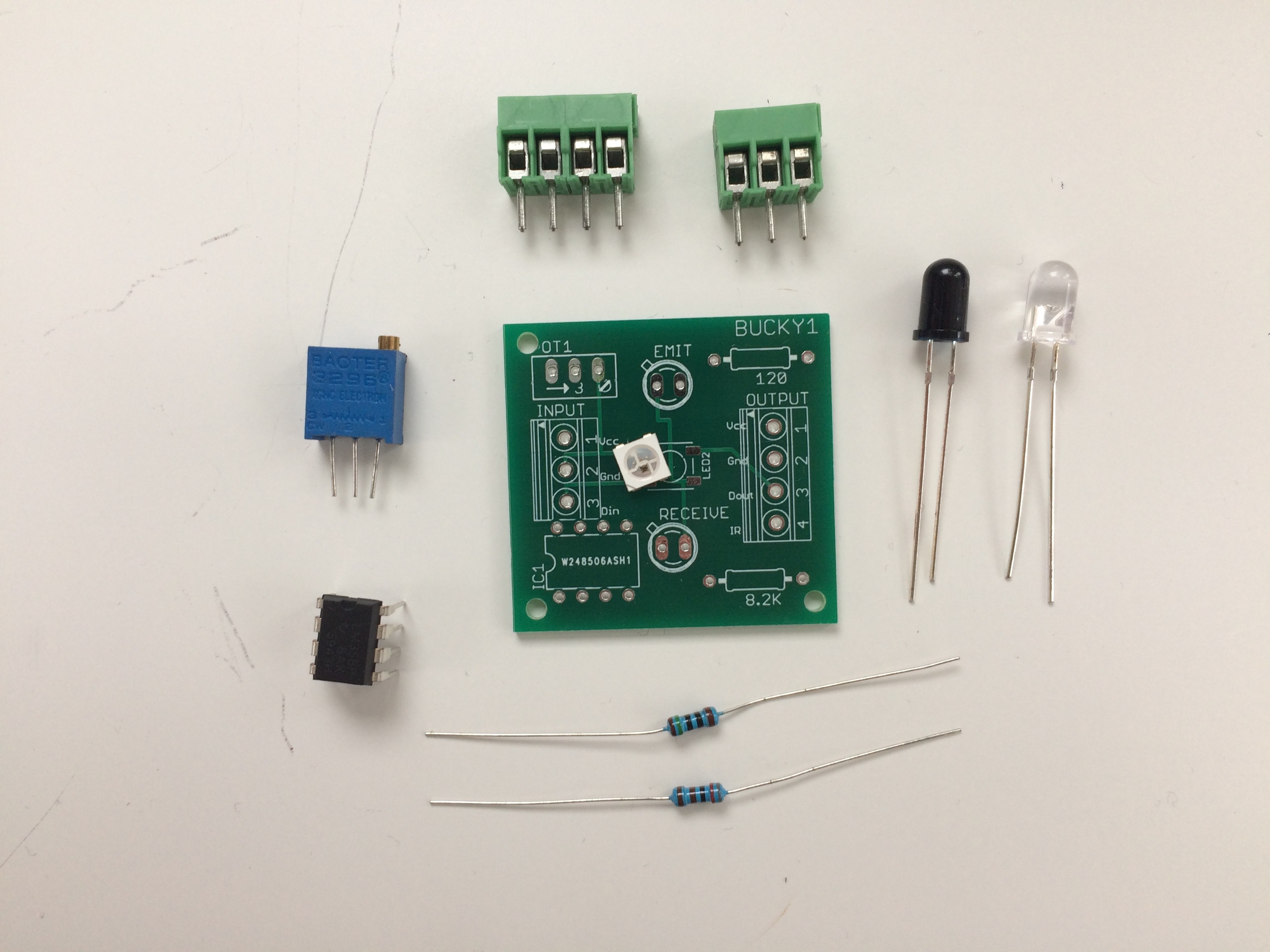
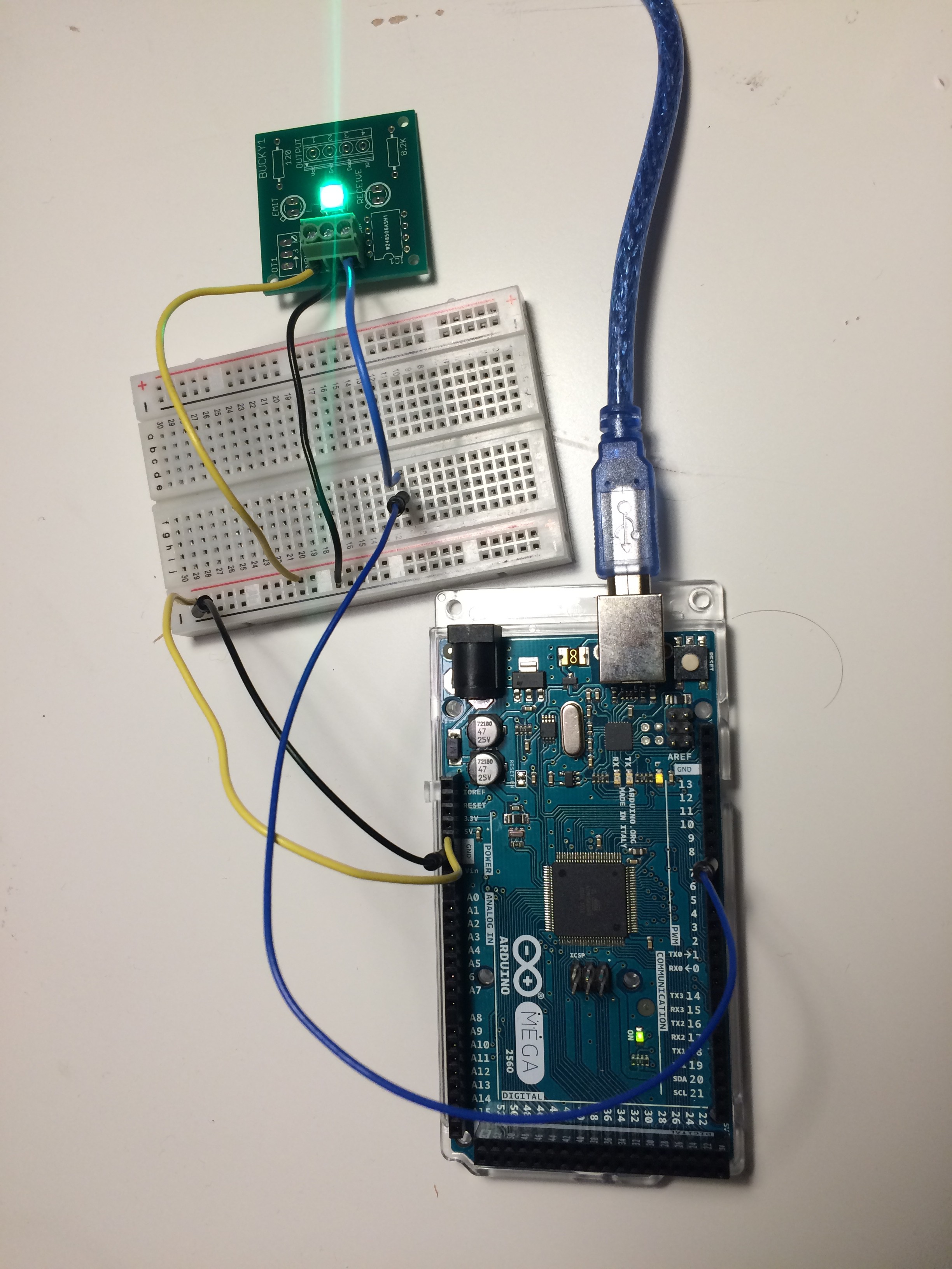
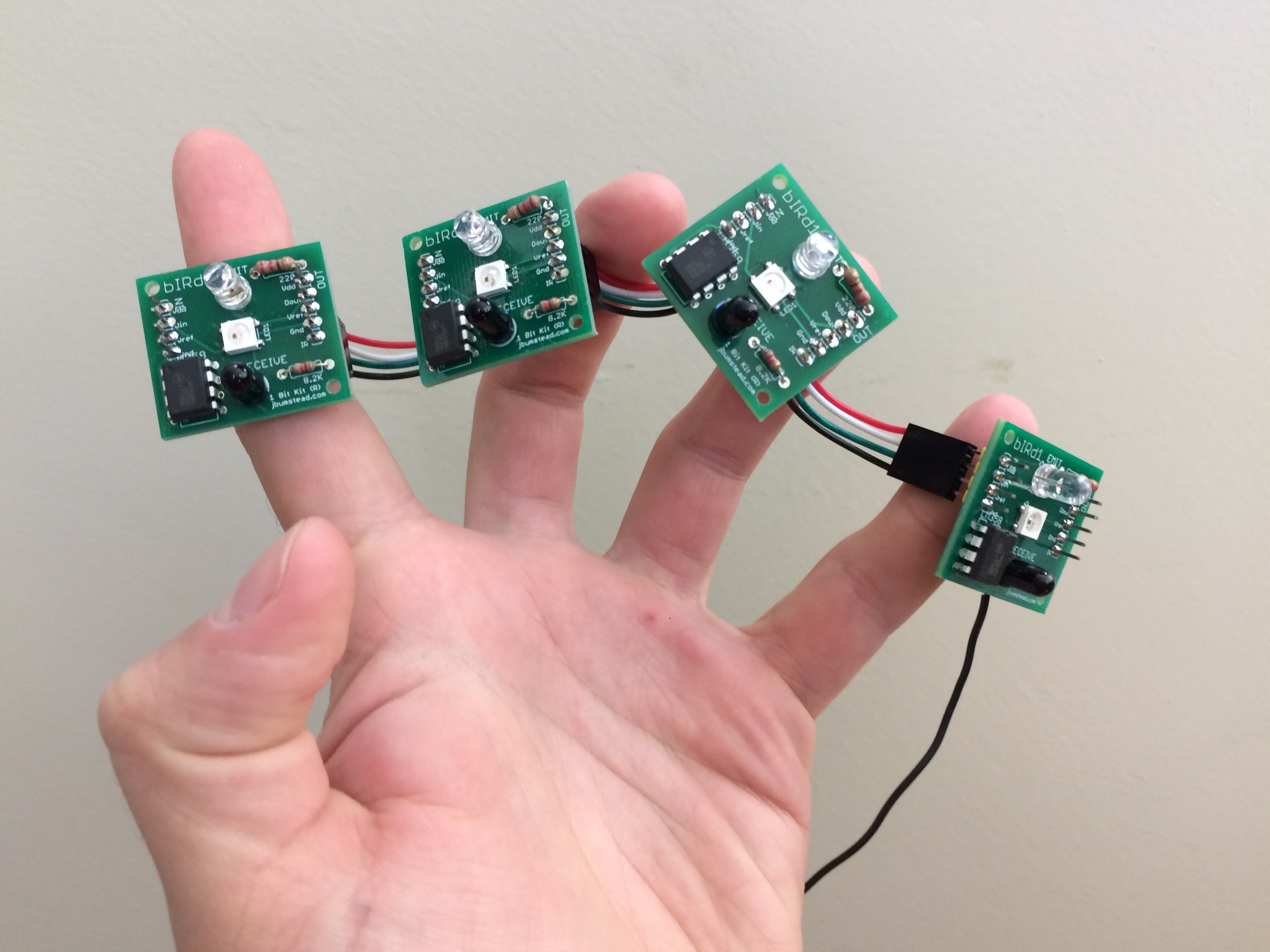
The output IR-LED board could then be connected to the next IR-LED in the circuit. Feeling confident in the design, I had the PCBs manufactured and shipped. I soldered several boards and started testing. The LED strip worked just fine, but then I started having issues with the IR sensors.
First, the outputs were heavily dependent on the lighting conditions. If there was too much IR radiation in the room, then the sensors would start to go off. I could handle this in software, but decided I wanted a better hardware solution.Second, the white plexiglass attenuated the IR radiation too much.
Third, the signal measured was highly dependent on the angle of the IR emitter and receiver. Because I wanted all the boards to have the same reference voltage for the comparator, varying signals that resulted from slight differences in how the IR emitter and receiver were mounted posed a major problem.
There were probably ways to make this PCB work in software and by paying close attention to soldering orientation, but in the end they just weren't reliable enough.
Version 1: Reference voltage on board
![]()
![]()
![]()
Version 2: Reference voltage off board
![]()
![]()
-
Pentagonal button design
09/08/2018 at 04:23 • 0 commentsThe breakout pins of the first Bucky Glow prototype enable you to customize the Bucky Glow for any sensor or MIDI, but I want the next prototype to play like an instrument. To achieve this, the faces of the Bucky Glow need to act as buttons. In my geodesic dome project, I used IR sensors for detecting when the user's hand was close to the surface. However, they were not not reliable because of IR radiation of the environment, crosstalk between IR sensors, and inaccurate measurements. For the Bucky Glow I have thought about different solutions: frequency encoded IR sensors, capacitive touch, and pushbuttons.
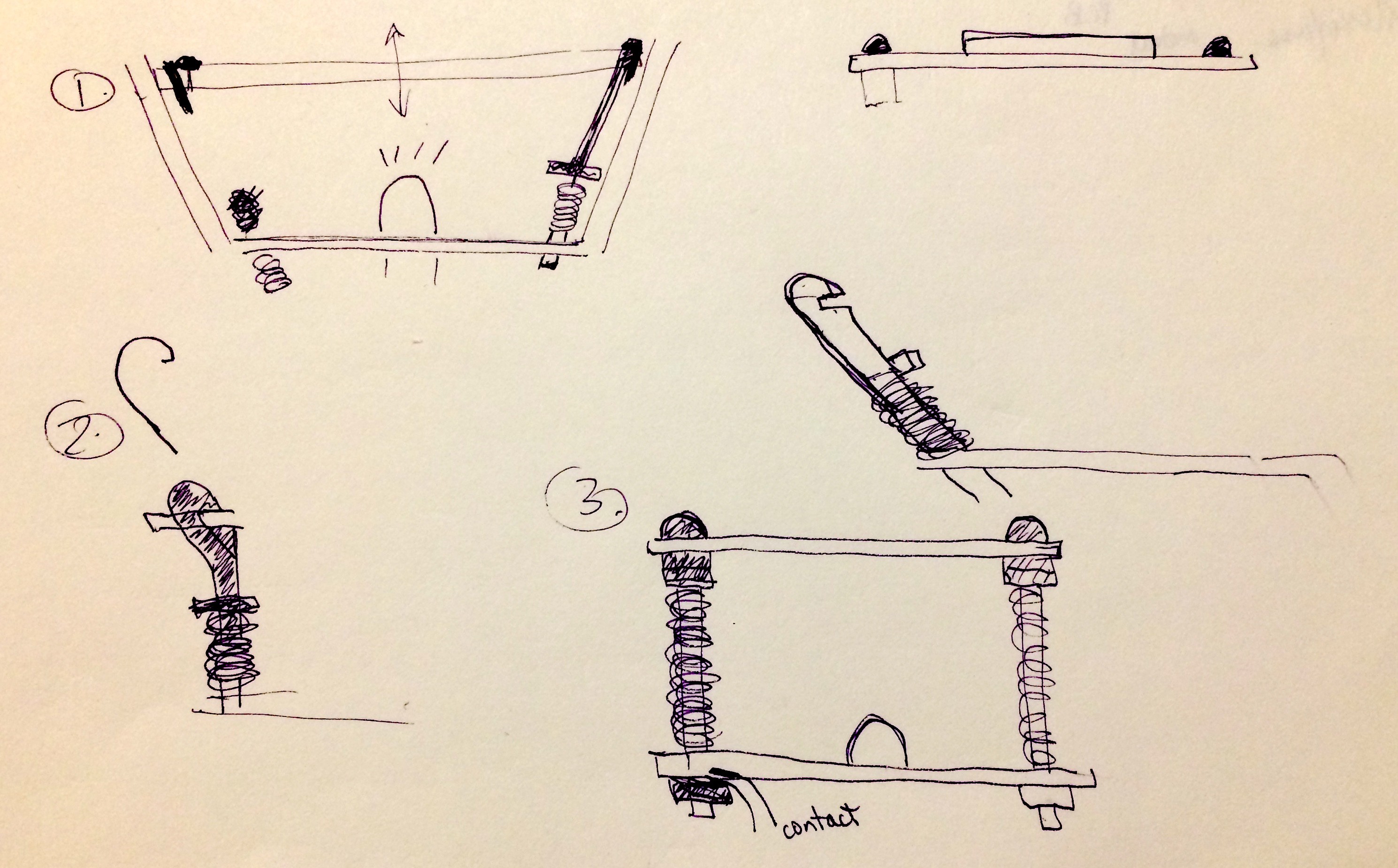
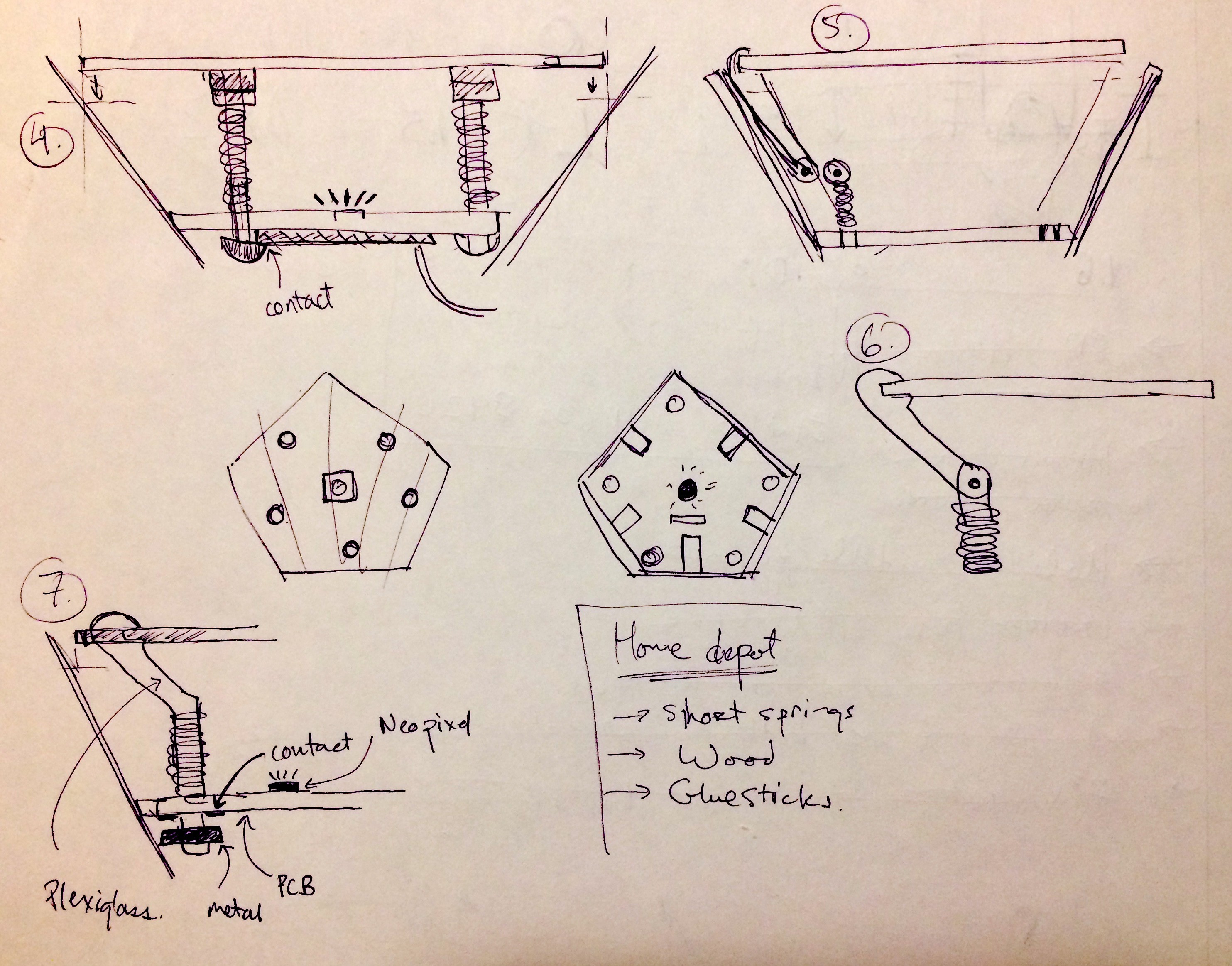
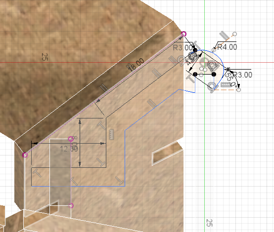
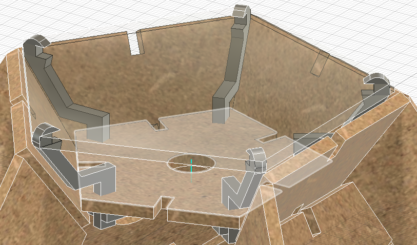
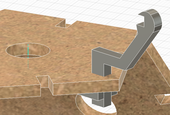
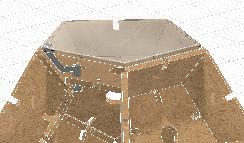
After running some preliminary tests, I have decided on going with pushbuttons. They are easy and dependable, and I think the action of the button will play more like the keys of a piano that touch sensors. The design started with a few rough sketches (see posted images). Now I am running through the modeling in Fusion. The idea is that the plexiglass pentagon will float above the walls of the Bucky Glow with spring-loaded arms. The end of the arm will make contact with a conductive material on the pentagon face.
![]()
![]()
![]()
![]()
![]()
![]()
![]()