Hunter Scott
-
Demo, schematic port, and HAL
09/29/2014 at 02:50 • 0 commentsI finished the 5 minute video required for the contest semifinals. It goes over some of the recent progress I've made and shows a quick demo.
Like I said in the video, the schematic port from Altuim to KiCAD is done. I've also got most of the Hardware Abstraction Layer (HAL) done as defined the a previous project log. I've been using a USRP to see what's going on in the frequency domain since I don't have two of these boards assembled yet, and because I don't have a spectrum analyzer. As usual, all the latest changes are up on Github.
-
Making level easy to use
09/21/2014 at 04:17 • 0 commentsUsability is a big part of engineering design. I want new users to be able to start playing with level as quickly as possible. The first way I'm accomplishing that is by enabling the use of Arduino shield libraries with level. As you know, level is not an Arduino shield, but it accepts shields in order to create bridges between whatever wireless experiments you're doing with level and a common standard like Bluetooth or WiFi or whatever other kind of interface you want. The libraries for these shields already exist, so this is a great way to leverage other work and not have to reinvent the wheel. I'm still developing this feature, but the end result will hopefully make it much easier for people to create new thing with level.
The second way I'm making things easier is by implementing an API/HAL for high level functionality. This way, you won't have to worry about setting a bunch of registers and bitmasks. Here's the functionality I have sketched out so far:
set_datarate(float) - Sets the datarate of the CC430. Returns 1 if the datarate is outside of what the CC430 can provide.
set_frequency(float) - Sets the transmit and receive frequency. Returns 1 if the frequency is out of bounds. Functionally, this programs the VCO. It may be possible to have separate transmit and receive frequencies, but I'm not sure how long the PLLs take to settle, so for now the HAL will only support a single transmit and receive frequency.
set_power(int) - Sets the transmit power. Returns 1 if out of bounds.
set_mode(string) - Takes in either "tx" or "rx" and puts the device into either transmit or receive mode. Returns 1 if not "tx" or "rx". Functionally, this controls the RF switches.
get_status(void) - Returns a struct of various status information.
get_device_id(void) - Returns device ID. Useful for simple testing.
set_message(char *buf, int length) - Takes in a pointer to a byte array and a length. The buffer is loaded into a FIFO for transmitting. If the buffer is larger than the FIFO, the FIFO is filled and transmitting automatically starts. This process repeats until the FIFO is loaded with the last chunk of data.
transmit_now(void) - This should always be called immediately after set_message(). This will force the transmit FIFO to empty by transmitting, which will send any fractional buffers still in the FIFO that did not fill it completely.
get_message() - Returns a pointer to a byte array that is the size of the receive FIFO. This array contains demodulated data from the CC430. It's up to the user to loop on this function until the end of message identifier is hit.
set_modulation(string) - Takes in "FSK", "GFSK", "MSK", "OOK", or "ASK". Sets the modulation used by the CC430.
This is all subject to change of course, but it's what I'm working on implementing now. This will first be implemented in C for use in programming the CC430 itself. I'd also like to implement a version of this for use over the SPI bus, so level can be commanded from another device.
-
Enclosure/Productized Design
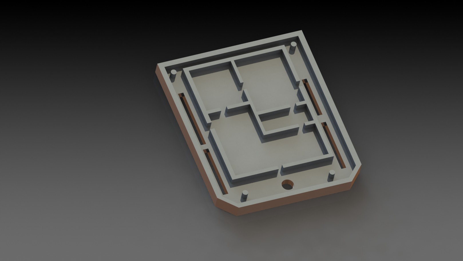
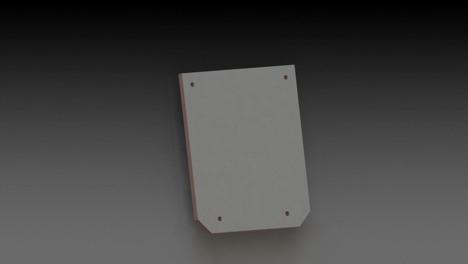
09/19/2014 at 05:42 • 0 commentsI threw together some quick drawings of what the final product may look like. This is my "artists representation". I tried to make design choices that made sense and that kept the design manufacturable. So here's what I came up with:

A couple things to note: not all the parts in these drawings are exactly to scale yet, and the exact dimensions will change based on the layout in the next iteration. The basic design is two parts that fit over the PCB, held together by 4 screws. There are several purposes this enclosure serves:
1) Protection against the elements and ESD damage from casual handling of the board.
2) Thermal relief for the circuit, since the entire enclosure is manufactured from aluminum and acts like a heat sink. This design should be able to be die cast, which will make it more manufacturable. Ideally this would be 7000 Aluminum, but I'm not sure if that's capable of being die cast.
3) Shielding for spurious radiation and interference from outside
4) Shielding for spurious radiation and interference from inside (caused by the circuit itself). Both 3) and 4) are very important in passing FCC emissions testing, so I'm hoping this (along with certain layout techniques) will keep this design FCC Part 15 compliant.
5) Shielding for self-interference. The raised channels on the inside of the first drawing will make direct contact with trace fences on the PCB. This effectively creates a tiny shield around each section of the circuit. This is important because this design uses heterodyning to generate frequencies, so there will be multiple copies of signals at different bands and amplitudes, plus harmonics, all very close to each other. Fencing in the CC430, ADF4351, mixer, and front end will prevent crosstalk and reduce noise and harmonics on adjacent traces.
I didn't want to design an enclosure that kept the user out though, so all you have to do is remove 4 screws and you can probe or modify the PCB however you want. I didn't include it in the rendering, but to help make this design more understandable, there will be silkscreened labels on the top of the enclosure beside the pins to identify each pin number and function.
Once I get the next revision done, I'll get a prototype of this 3D printed in at least plastic, maybe metal. I may also play with the aesthetics a little and try to use depth more. I don't want to design anything that can't be achieved with die casting, but I think there are still some things I can get away with.
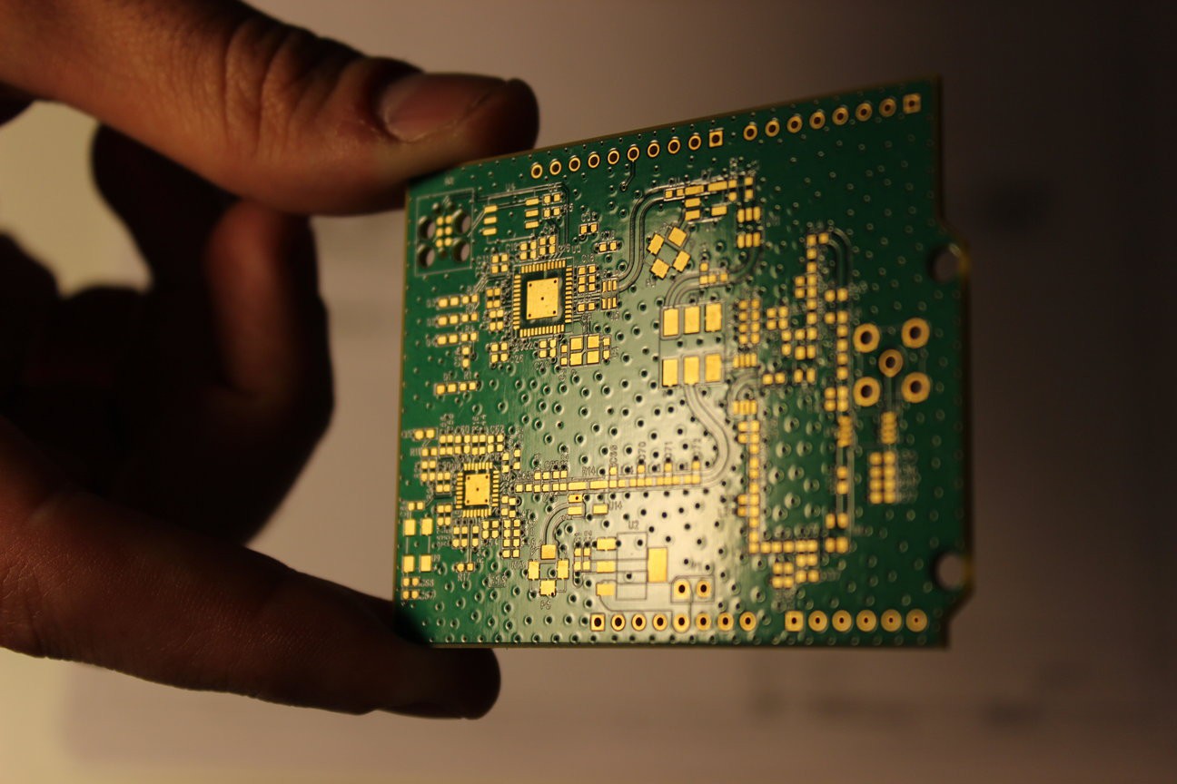
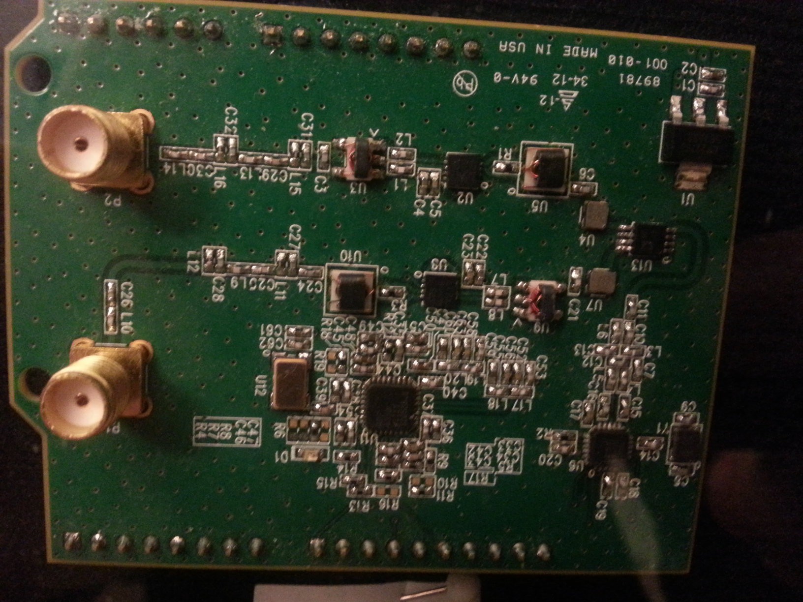
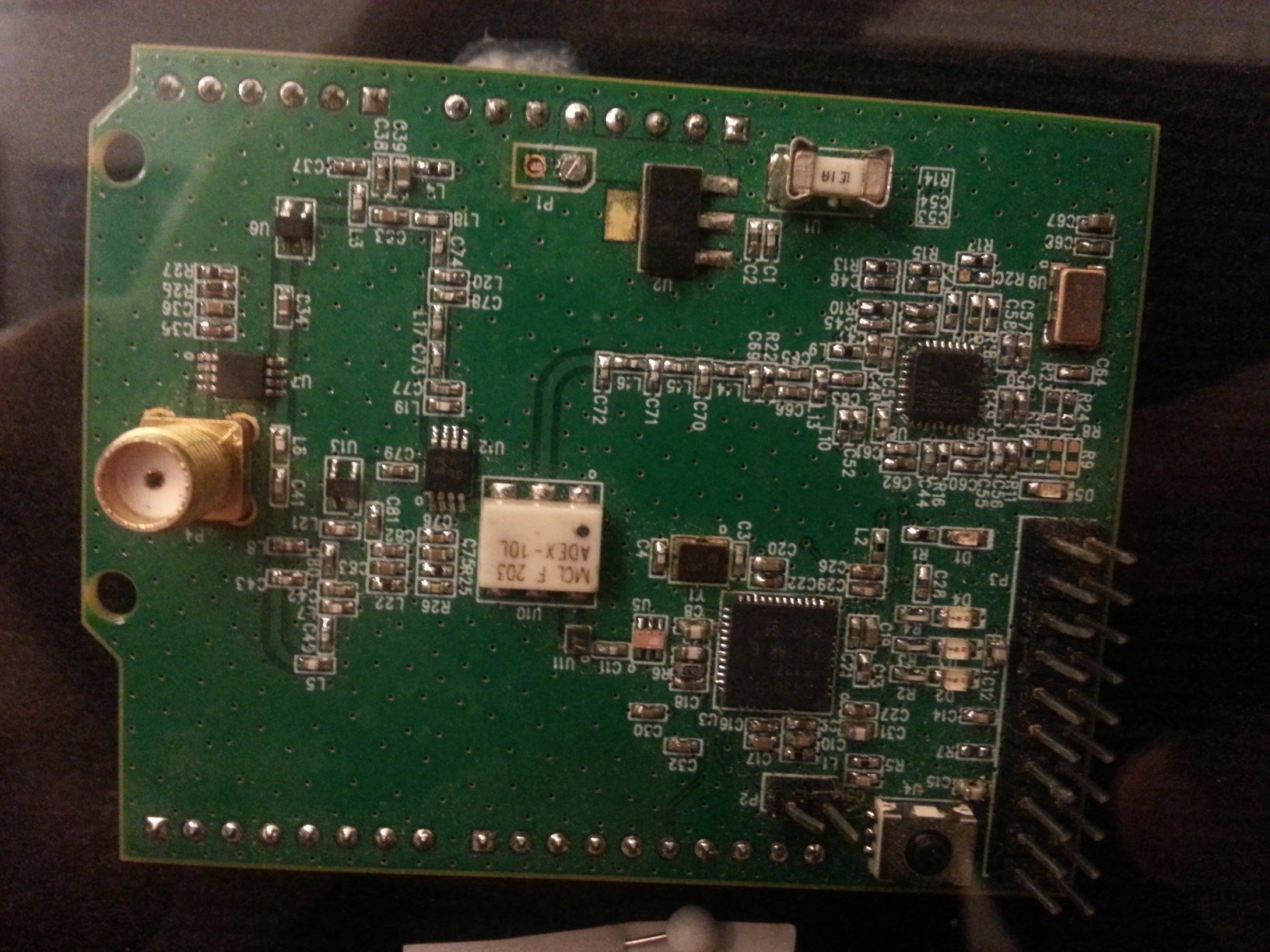
While I'm on the subject of productization, one of the often overlooked problems with getting an electronic product to market is FCC certification. Part 15 says that a device can't cause interference and must accept any interference it encounters. There are lots of good design practices used to help meet this certification. For example, having lots of easy paths to ground prevents stray inductance from occurring. That's why there are so many vias on the board:
I don't know if this will pass EMC testing, but I'm keeping it in mind and I'm hoping the combination of good layout techniques and the enclosure will make passing it easier.
-
Towards a more open level
09/14/2014 at 23:55 • 0 commentsToday I made a few changes that make level more open than before. First, I added support to building with msp430-gcc in addition to Code Composer Studio. That means that a lot of the supporting libraries and code that was under TI's license is now under the BSD and GPLv2 licenses.
The other thing I did was change the license of my code from Creative Commons to the MIT license. The MIT license is simpler and less restrictive. There's also good news for SimpliciTI: I found a guy who ported it to GNU C. That may be an avenue towards a more open MAC without writing one myself.
The last thing that I'm doing (currently in progress) is drawing the next hardware revision in KiCAD instead of Altium. Altium is closed source and costs money, so doubly bad. KiCAD is maturing pretty quickly now that CERN is developing it and this will be my first major design using KiCAD. The HackRF One by Michael Ossmann is another example of an RF board that was designed and layed out in KiCAD, so that improves my confidence in the ability of KiCAD to work well enough.
-
Overview and other things
08/17/2014 at 21:16 • 0 commentsHere's my overview video:
I only had 2 minutes, so it skips a lot of details. Here's a schematic walkthrough that goes into a little more detail:
I also wanted to address one other thing that no one has brought up yet, but I imagine may cause some confusion. I've said that this board can do 30 MHz to 4.4 GHz, but it's also narrowband. What I mean by that is the frequency synthesizer, CC430, and mixer can achieve that range (using the new mixer), but the instantaneous bandwidth is only 812 kHz. The current design has filtering for UHF. So to change the frequency to a different band (like S band), different filter values need to be used. In a real software defined radio, this would be done digitally in an FPGA. I want to change the filtering in the next version, but I haven't decided how to do it yet. Maybe an Igloo Nano or a small discrete filter bank or something. I don't want to just replicate a HackRF or Myriad RF or BladeRF or USRP, I want to make a lower performance, lower cost, and lower power radio module.
-
Previous versions
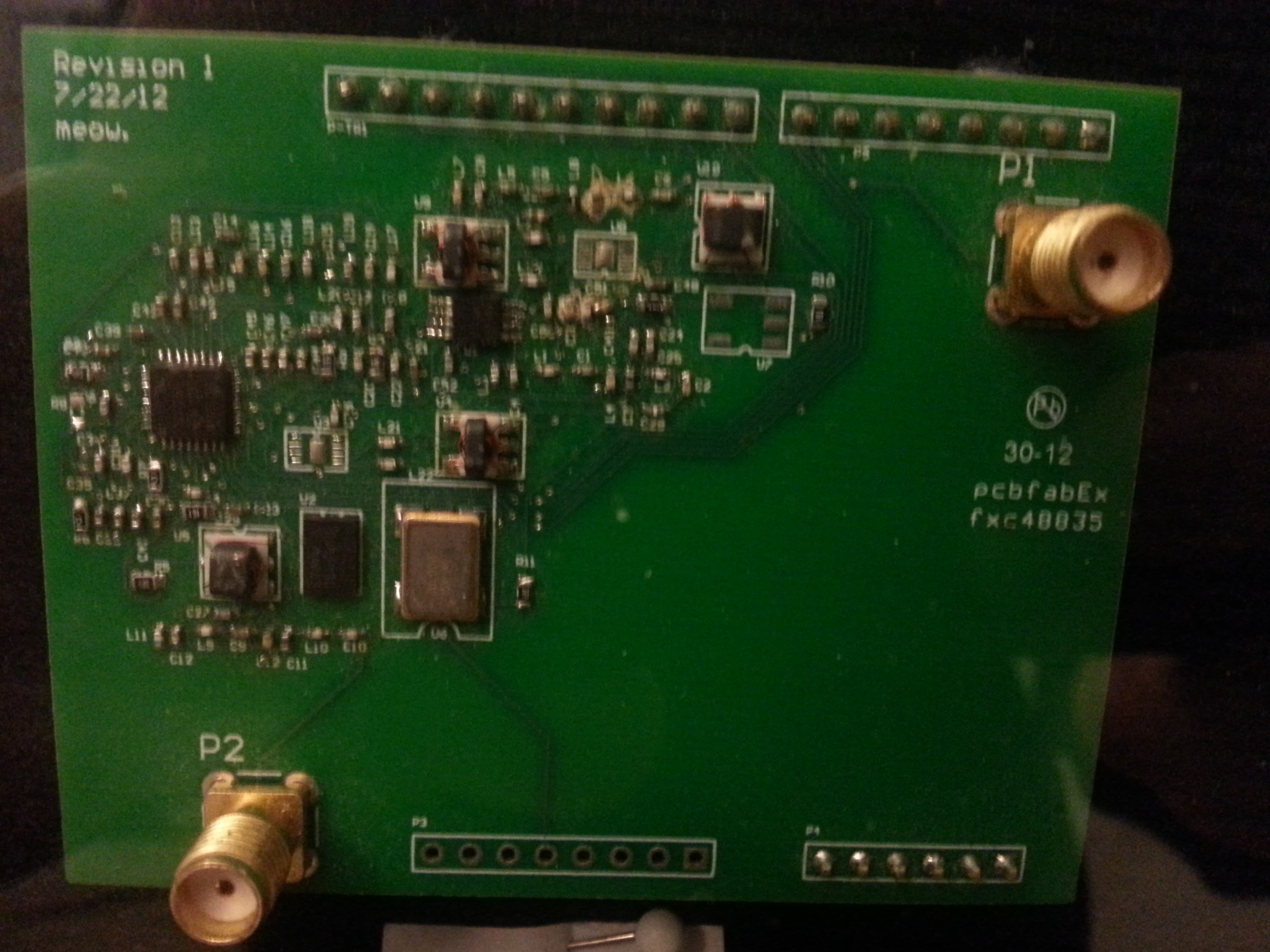
07/26/2014 at 02:56 • 0 commentsThis board wasn't created in a vacuum, and it wasn't created all at once. This is the 4th spin of the board, actually, and most of the previous versions used entirely different architectures and parts. Here's the first version:
It's old! It also didn't work at all.
Version 2:
This one was better, but it had seperate TX and RX paths, so needed 2 antennas.
Version 3:
Getting closer. A bunch more changes, and this is basically the current version, minus a few tweaks and fixes.
This is/was the first RF board I've ever done, so I'm learning as I go!
-
Protocol stack for mesh network
07/20/2014 at 19:21 • 0 commentsI forgot to mention this before, but I've been experimenting with TI's SimpliciTi mesh networking protocol for talking between devices. I like it because it's open source and designed for applications like Level. Another protocol I was looking at was BATMAN (Better Approach To Mobiel Ad-hoc Networking), which is a robust, fast protocol for P2P networks. I have an implementation for a network simulator I got from the researchers who published the paper on it, but I haven't implemented it on a real device yet. There's another implementation here (along with some other mesh networking protocols) that may be good to play with.
I also have some code written in GNU Radio for the USRP that can communicate with stock CCxx devices using the basic packet structure of SimpliciTi. It's still a little buggy, but I've gotten it to work. You can find it here: https://github.com/blueintegral/Cognitive-Basestation/tree/master/level
I don't have access to a signal or spectrum analyzer anymore, so it's difficult for me to debug some stuff. I want to pick up a Tek 492 with options 1, 2, and 3, so if you've got one you want to sell for cheap, let me know!
-
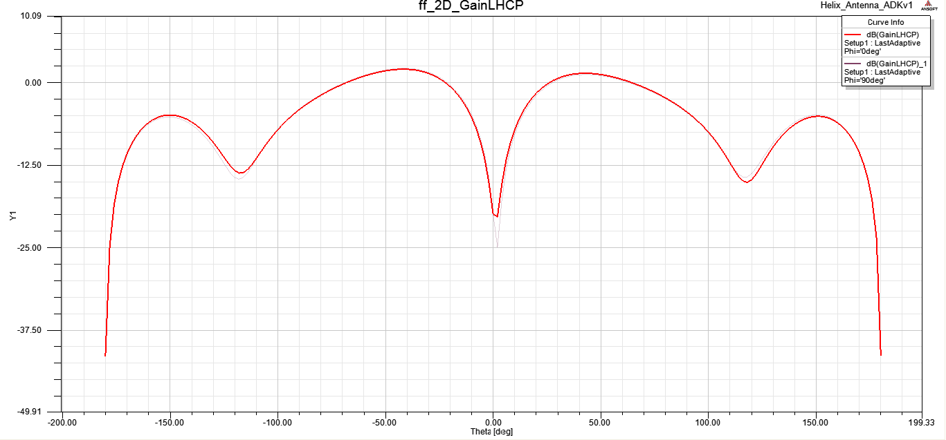
Antennas
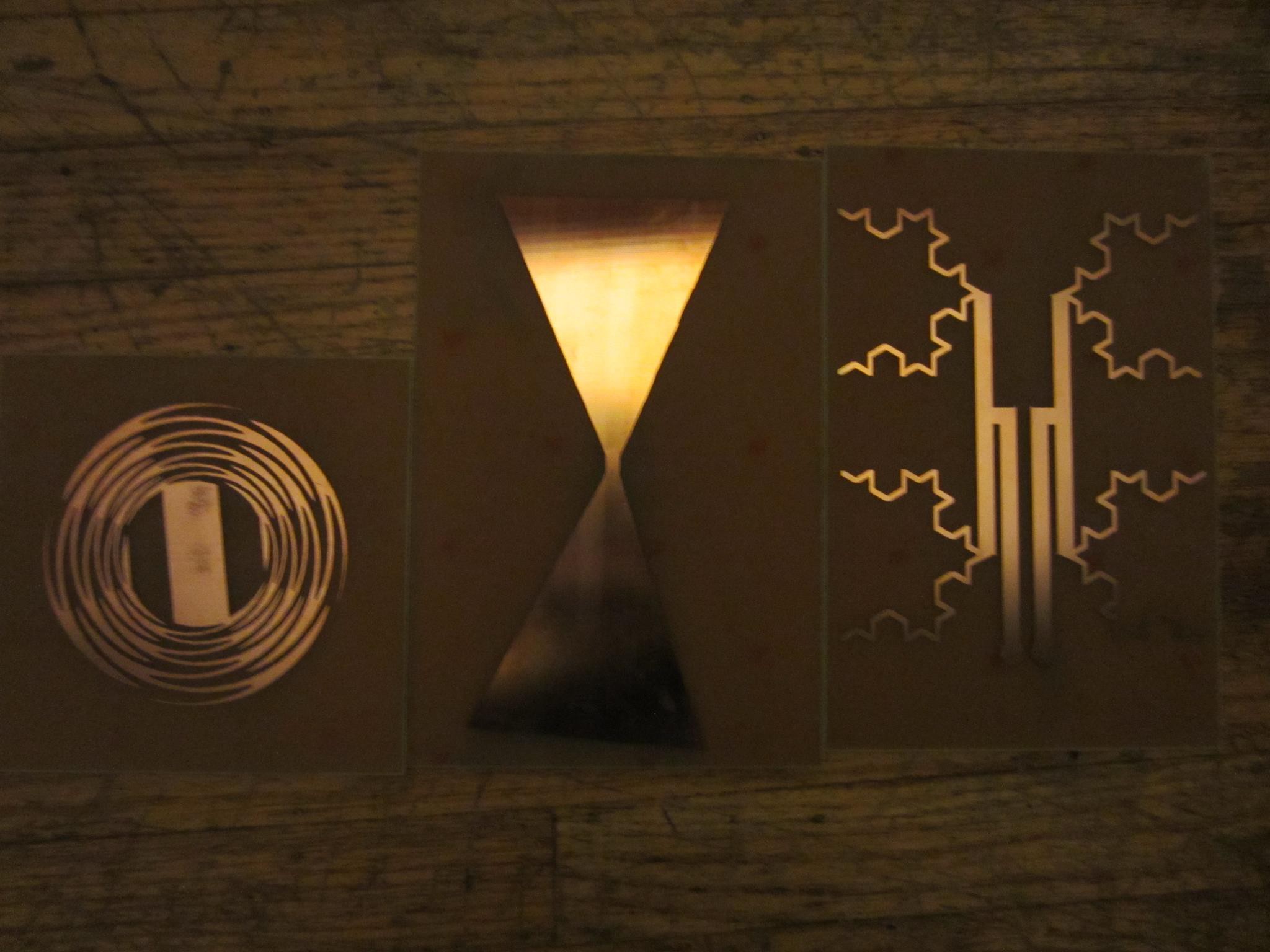
06/25/2014 at 01:40 • 0 commentsExperimented with some antennas.
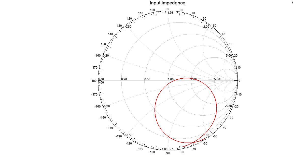
These were designed in HFSS and are targeted for the UHF band. Here are some simulations for the spiral antenna:
level: A New Kind of Radio Module
An agile radio designed for low power and narrow bandwidths over a wide frequency range.