-
Finished, Final Results
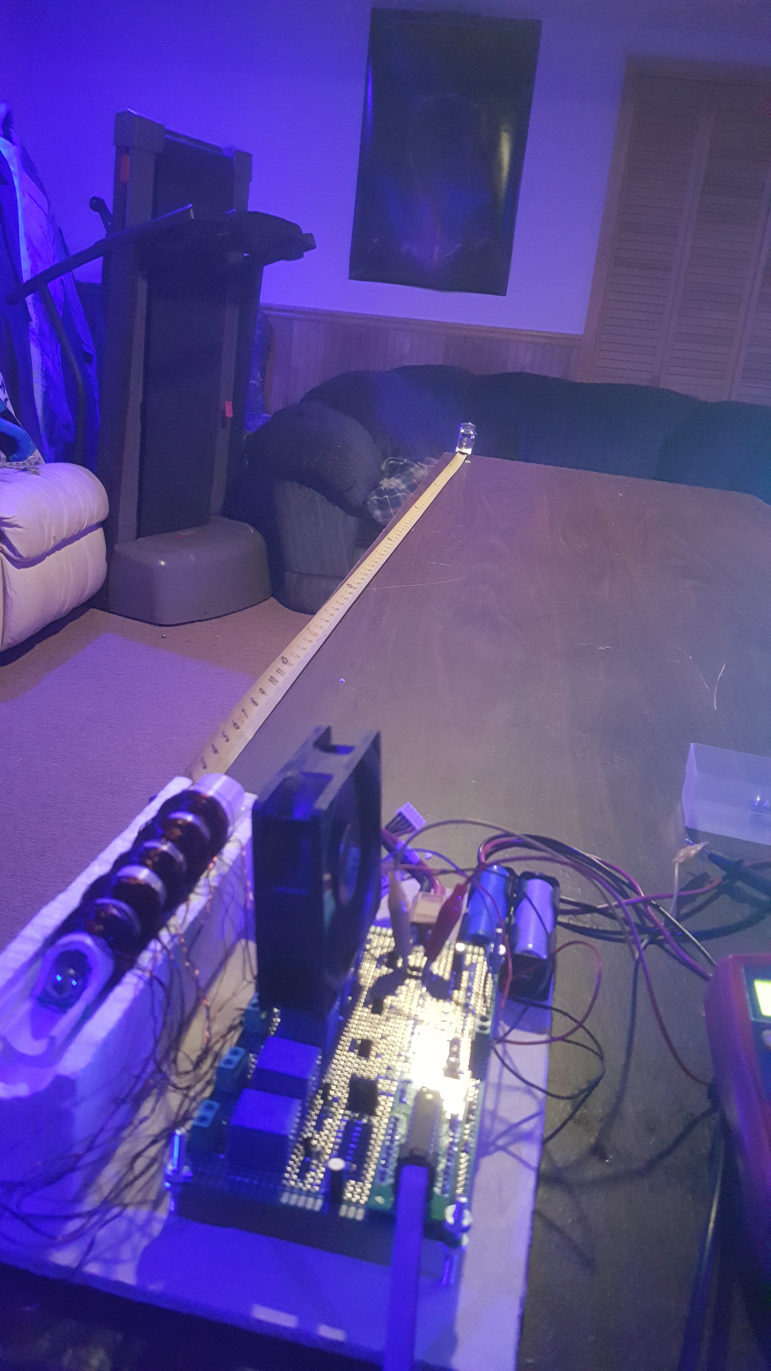
07/07/2018 at 04:47 • 0 commentsand that's it, a short and sweet project. the end result of this is that I was able to get a 1/4" ball bearing to travel 14 inches horizontally with a 2 inch elevation of the barrel. not exactly the most stellar results, but i'm glad i did it, and as a proof of concept it works.
the timing was kind of a pain, here was my basic setup
![]()
since I don't have any feedback, I just had to start with one coil at a time and move my way through, finding (roughly) what timing got me the furthest distance. I feel like the project could work better if I put even more time into getting the coils to fire perfectly, but i'm satisfied with the way it is now.
and here's the coilgun is working!!!
onto the next project!
-
Extra Coil and Isolation - Circuitry completed
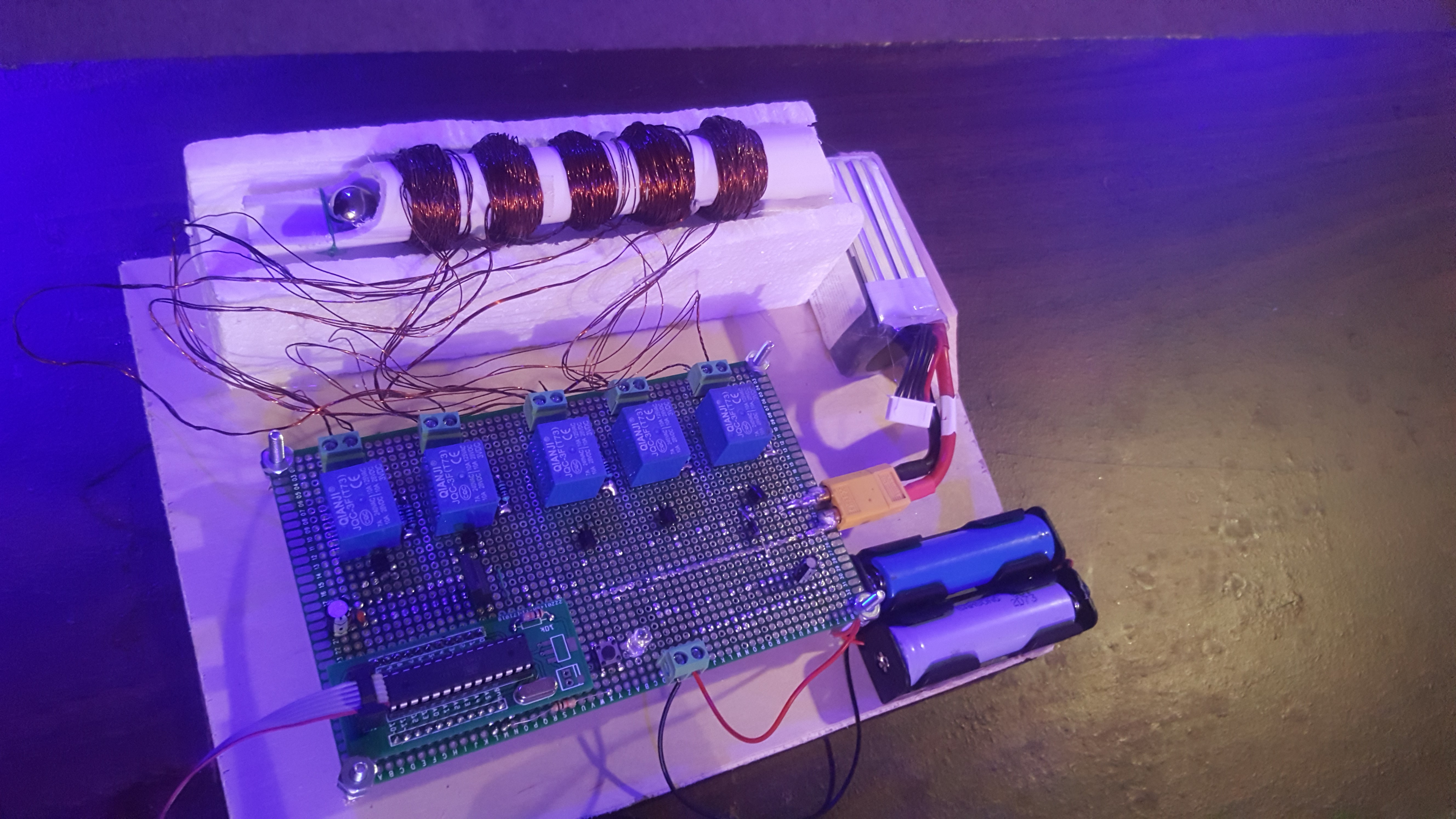
07/06/2018 at 23:20 • 0 commentsthe circuitry for this project is now complete. Since this project uses relays to power the coils i decided there wasn't a good reason to keep the micro-controller and transistors on the same circuit as the coil's themselves. This resolved an issue i was experiencing where the micro-controller would reset for seemingly no reason. It did however add another set of batteries to deal with, but i can live with that. now all that's left is to work out the timing to fire the 1/4" ball bearings that this coilgun was designed for.
![]()
-
how this got started, and basic design
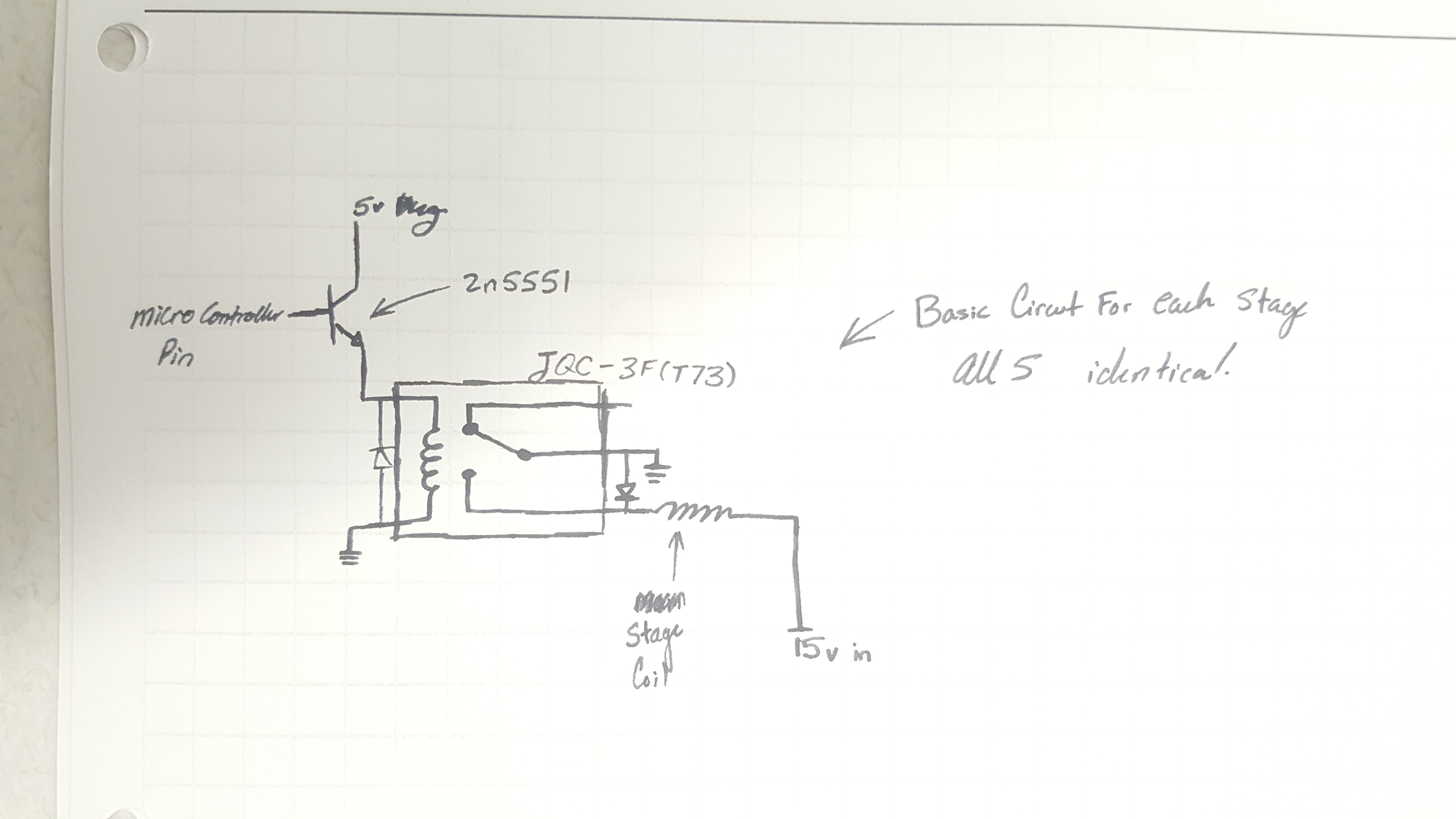
07/05/2018 at 19:29 • 0 commentsso this is really a project that was born of boredom, i was sitting around one morning and i just wanted to do a project. so i took something I've tried many times. after a few hours of soldering i ended up with a buggy protoboard prototype that seemed to look right. I wrote the code for it in about 20 minutes and gave it a shot... and it worked! twice.... added some flyback diodes to every coil in the circuit and tried it again with better results. i drew up a schematic to illustrate how each stage is wired and how i have it connected to the micro-controller.
![]()
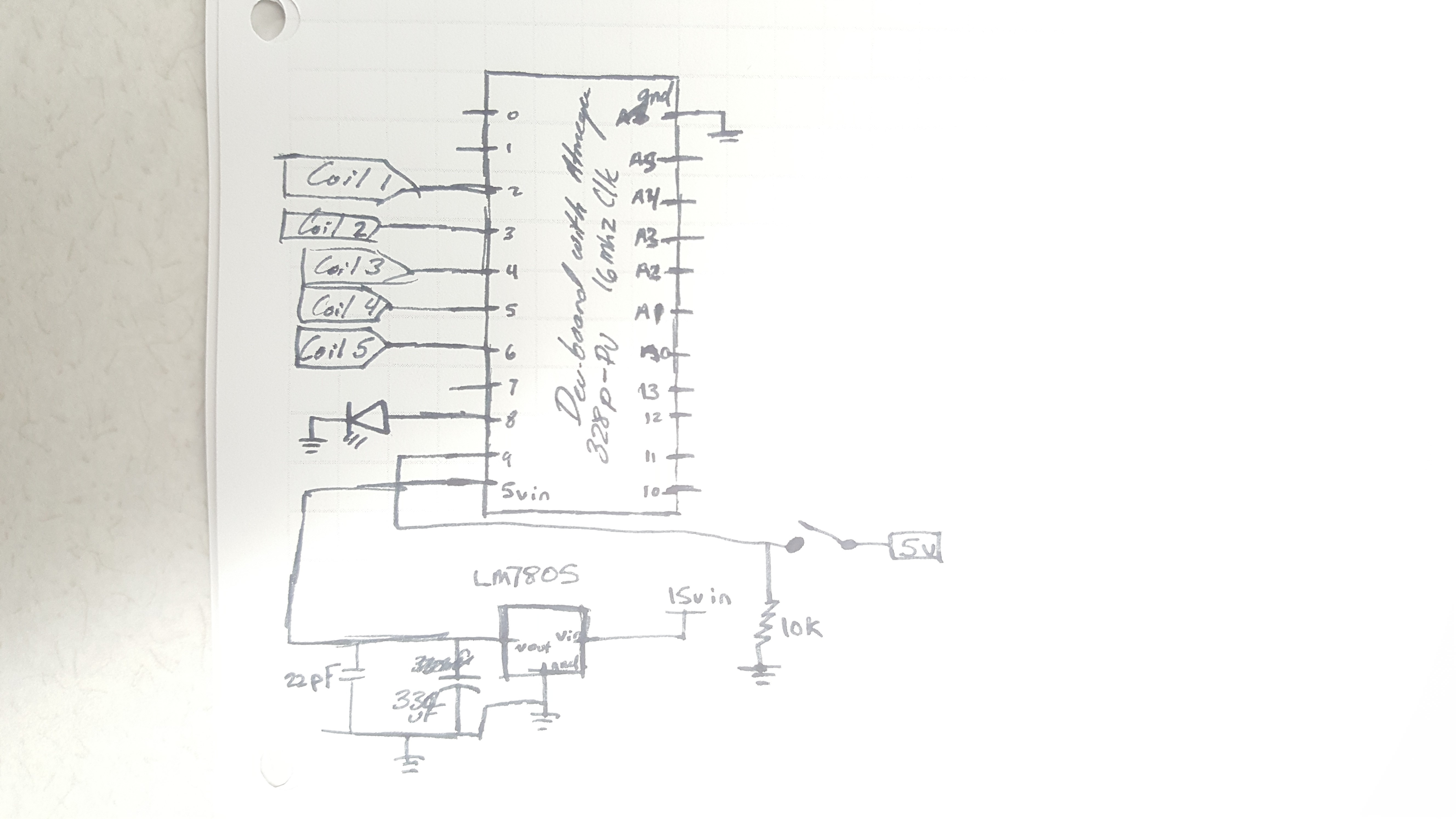
the micro-controller diagram is a bit messy, it uses an Lm7805 linear regulator with a 330uF electrolytic cap and a 22pF ceramic cap on the output. other than that most of the circuit real-estate is composed of the relay circuit which is above, each pin connects to the 2n5551 in its respective circuit.
![]()
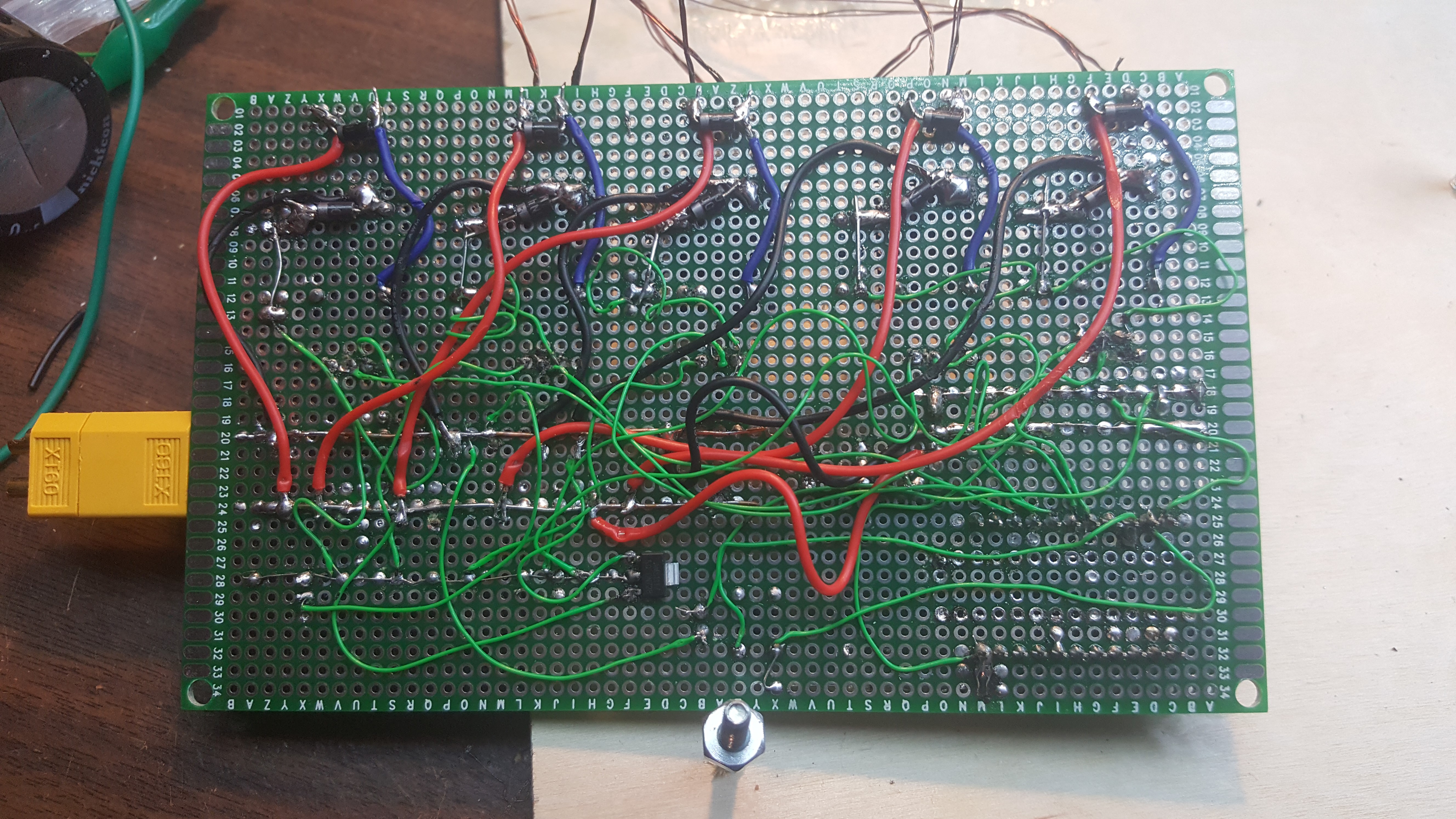
and that's basically all this mess of wires is
![]()
also, the micro controller and the 2n5551s draw from different 5v regulators, the 7805 powers the micro controller while the collector of each transistor is powered by the Vout of a AMS1117. i don't exactly remember why i did it, but it's more work to fix it than leave it.
 Matthew James Bellafaire