Christoph
-
Day 3: Y Axis
07/30/2018 at 17:00 • 0 commentsTo conceal the rough ends of the rails, I covered them with printed end caps, which also act as belt tensioners. The belt brackets are fastened to the end caps and tightened using M3 screws. Afterwards, I fixed them to the rails with more M3 screws to take some of the stress off the caps.
![]()
For testing, I connected the stepper motors to an Arduino CNC shield and tested out different speeds and accelerations. Sadly, the limit seems to be around 100mm/s, which is really, really slow for a PnP machine. Changing the Y axis to servo drive will be one of the first upgrades after everything else is working.
I'm already thinking about building my own BLDC servo using a standard 2212 motor with a printed encoder. If it works, it should allow the heads to move up and down fast enough. I need to continue with the head design now before going any further with this build, because the head will determine which motors I can use on the X axis.
-
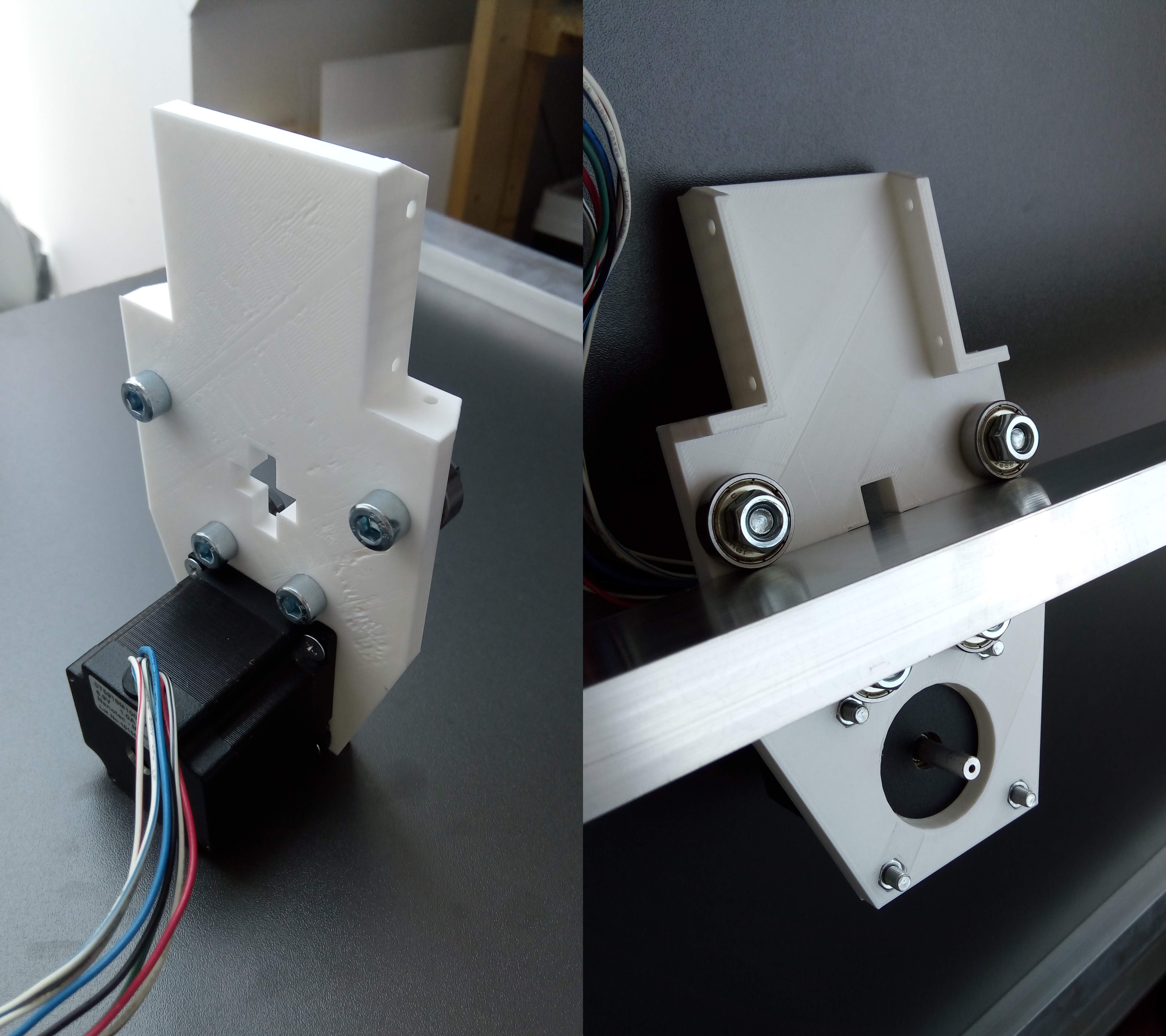
Day 2: Gantry
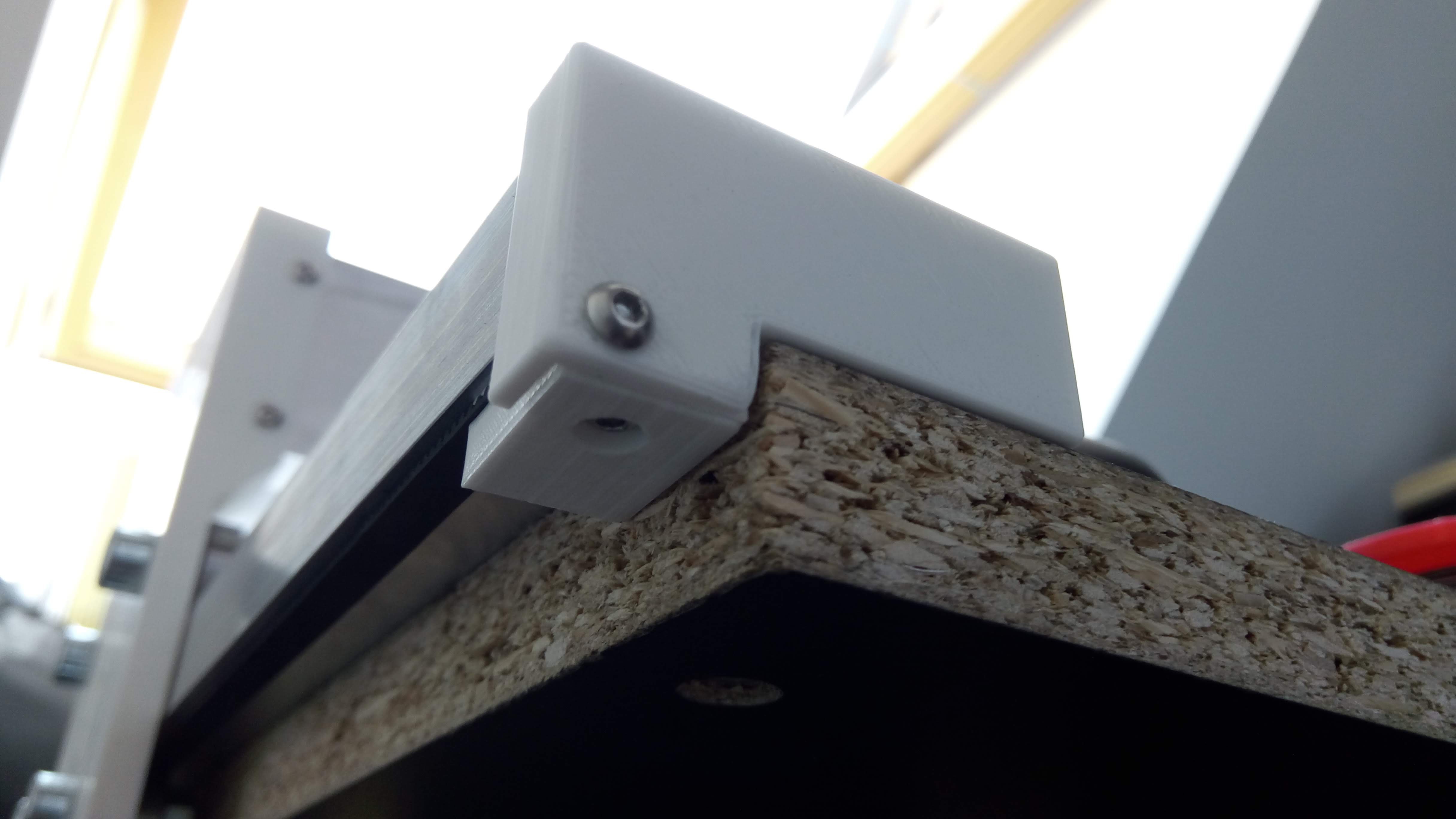
07/18/2018 at 17:46 • 0 commentsThe y carriages came out of the 3d printer and they fit to the rails almost perfectly. I'm very lazy, so I made the carriages so they fit tightly around the ends of the rails, thereby covering the ugly hand-sawn ends. They are firmly held in place by M3 screws. The ball bearings roll over the y rails smoothly enough, though I have discovered that even a small piece of dirt makes the wheels slide instead of spin. I guess I'll have to keep the rails clean.
![]()
![]()
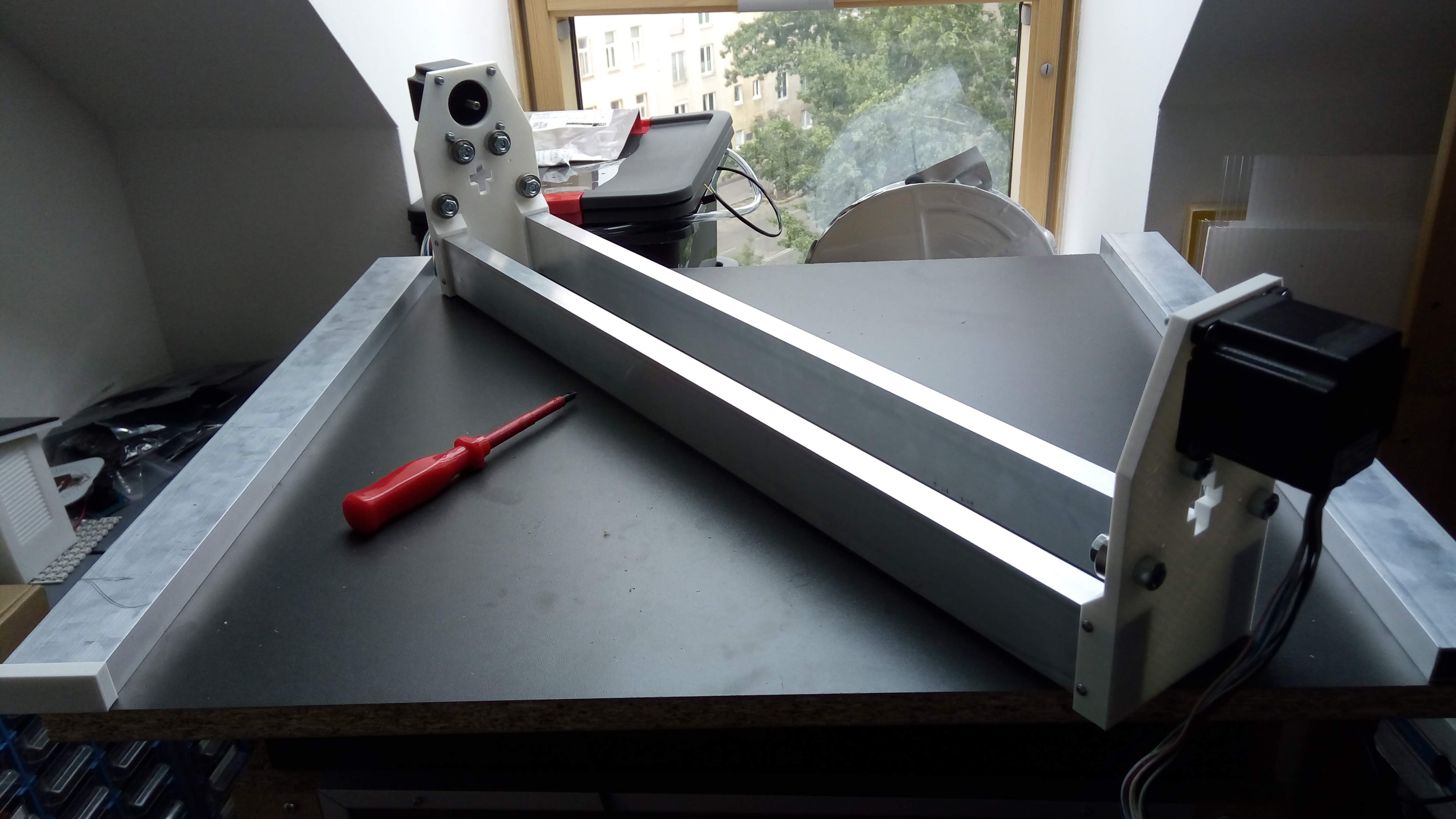
The gantry is driven by one NEMA23 motor at each end. The beauty of this design is that the gantry will align itself automatically to be square to the base as long as the endstops are mounted accurately (and the motors don't lose steps, which would be bad anyway). I only have to add one bearing to each side to keep the gantry from sliding left to right. One of these bearings will be mounted firmly to the carriage, while the other will be pushed against the rail to eliminate clearance.
The next step will be to attach the GT2 belts to the y rails and make the gantry move on its own.
-
Day 1: Base
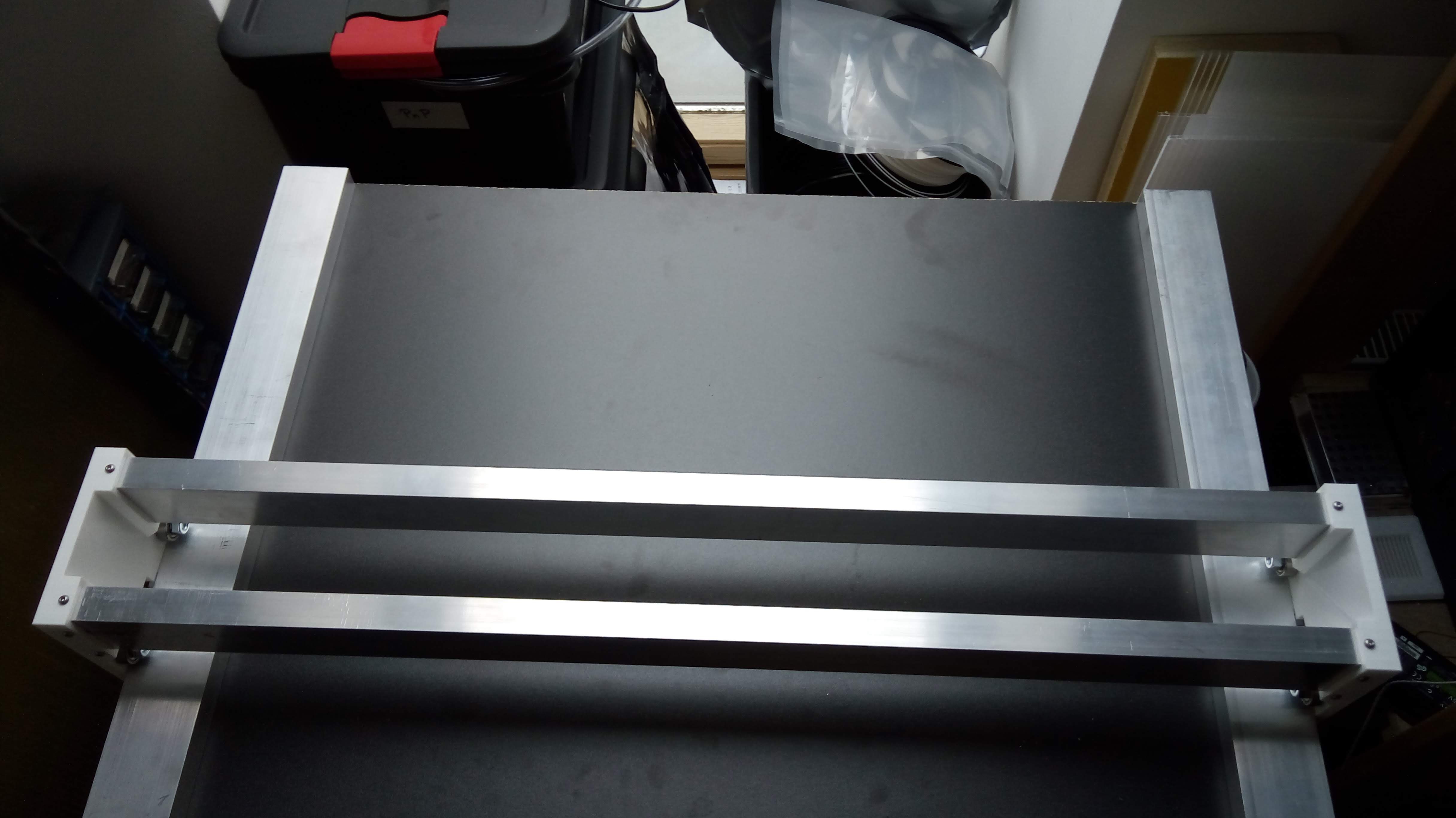
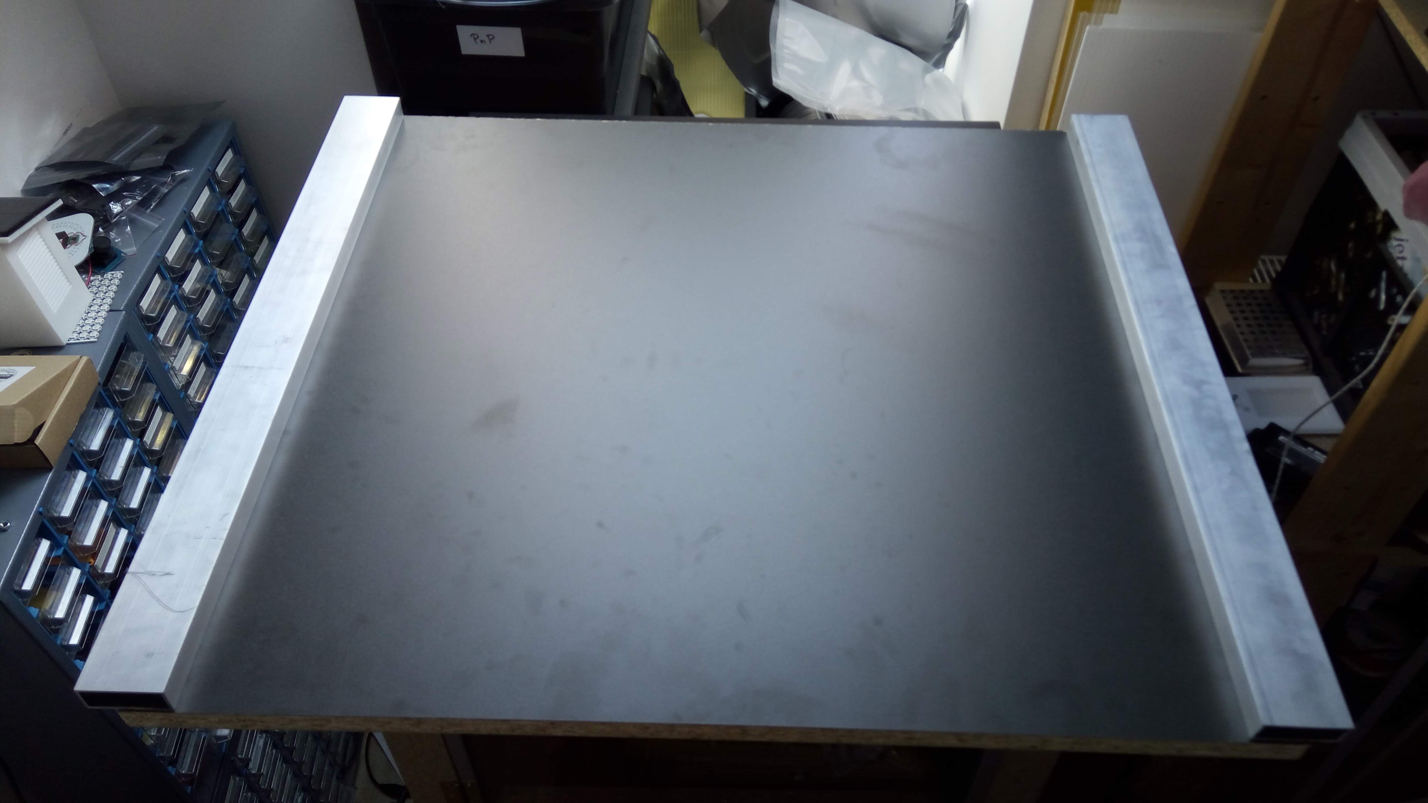
07/15/2018 at 16:33 • 0 commentsI went shopping for parts yesterday, and returned with a base plate which was a bit larger (but much cheaper) than I had intended. As I can't use a circular saw in my apartment, I just updated the design to use a larger base (more feeders, yay!). I manually cut the side rails, which are 50x20mm extruded aluminum, and screwed them to the base using M5 bolts. The distance between the outer edges is 709mm now and they overlap the base by about 16mm on each side.
![]()
I also tested the design for the Y carriages, which are 3d printed in PLA and run on skateboard bearings. I think I have a working design now, but I'll know for sure when the gantry is rolling on the rails (hopefully tomorrow).
![]()