 Open Green Energy
-
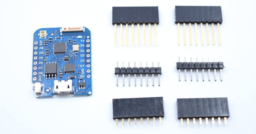
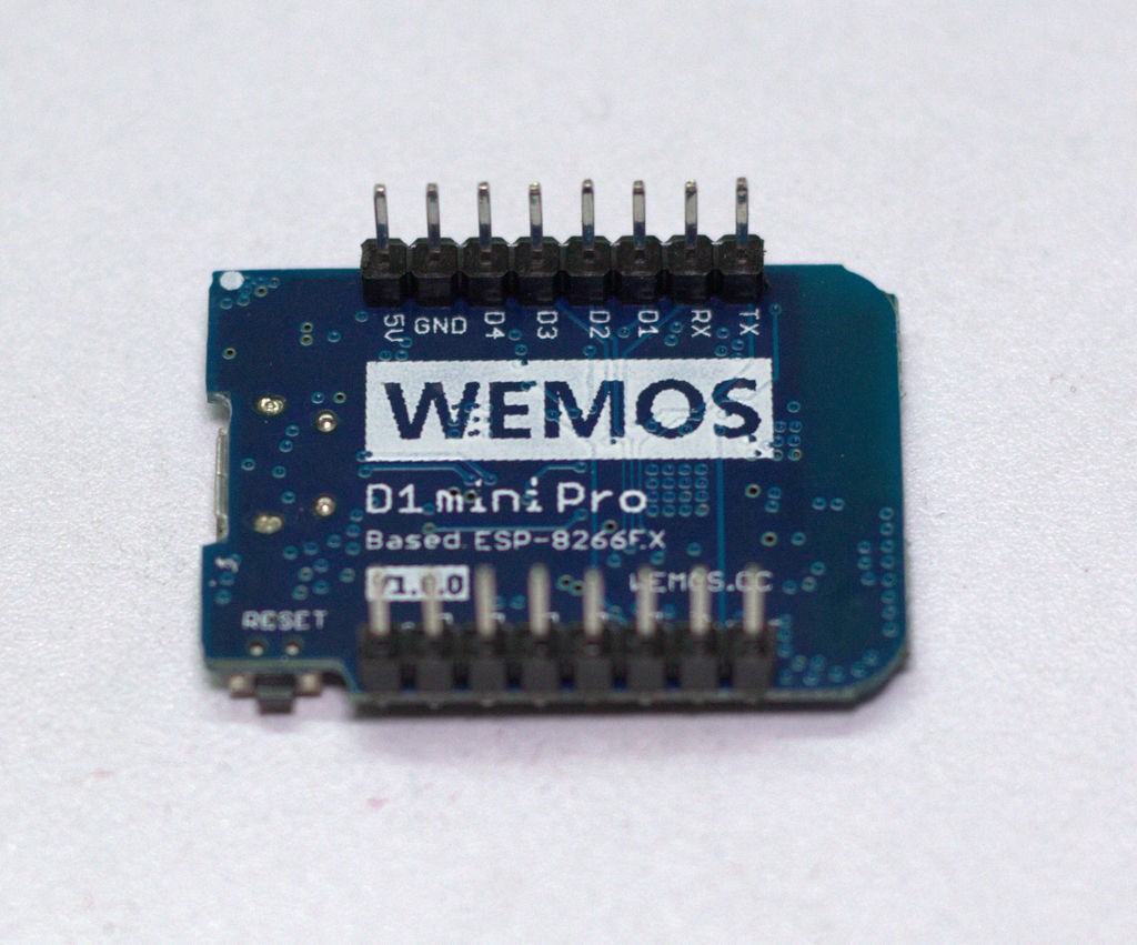
1Solder the Headers
![]()
![]()
Wemos modules come with variety of headers but you have to solder it according your requirement.
For this project,
1. Solder the two male headers to the Wemos D1 pro mini board.
2. Solder a 4 pin male header to the BMP 280 module.
After soldering the headers the module will look as shown in the above picture.
-
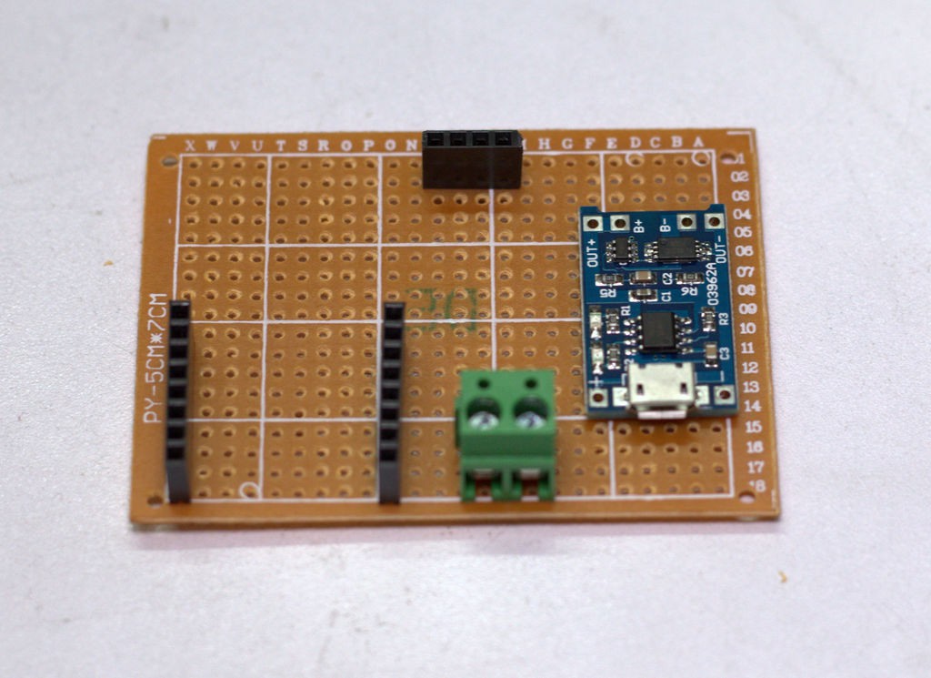
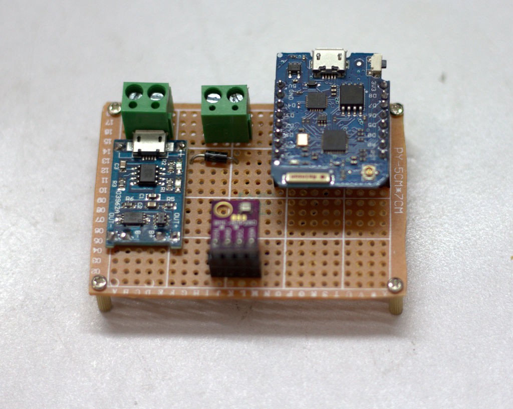
2Adding Headers and Terminals
![]()
Next step is soldering the headers to the perforated board.
1. First place the Wemos board over the perforated board and mark the foot print.Then solder the two row of female headers over the marked position.
2. Then solder a 4 pin female headers as shown in the picture.
3. Solder a screw terminals for battery connection.
-
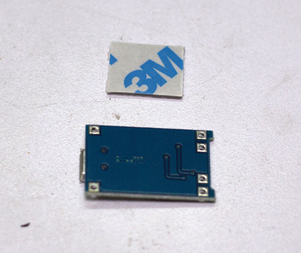
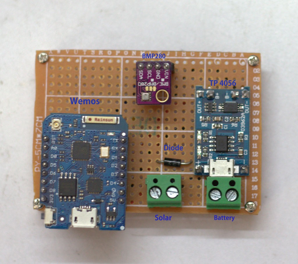
3Mount the Charging Board :
![]()
![]()
Stick a small piece of double sided tap on the back side of the charging module and then paste it on the perforated board as shown in the picture.During mounting care should be taken to align the board in such a way that the soldering holes will match with the perforated board holes.
Adding terminal for Solar Panel
Solder a screw terminal just near the micro USB port of the charging board.
You can solder this terminal in the earlier step also.
-
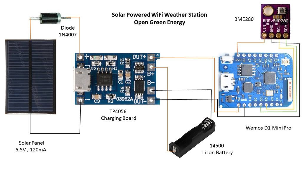
4Wiring Diagram
![]()
![]()
First I cut small pieces of different colors wires and strip out the insulation at the both ends.
Then I solder the wires according to the Schematic diagram as shown in the above picture.
Wemos -> BME 280
3.3 V - -> Vin
GND --> GND
D1 --> SCL
D2 --> SDA
TP4056 Connection
Solar Panel terminal -> + and - near the micro USB port
Battery Terminal -> B+ and B-
5V and GND of Wemos -> Out+ and Out-
Note :In the picture , I have used a 1N4007 diode but you can omit it.
-
5Installing the Parts inside the Enclosure
![]()
![]()
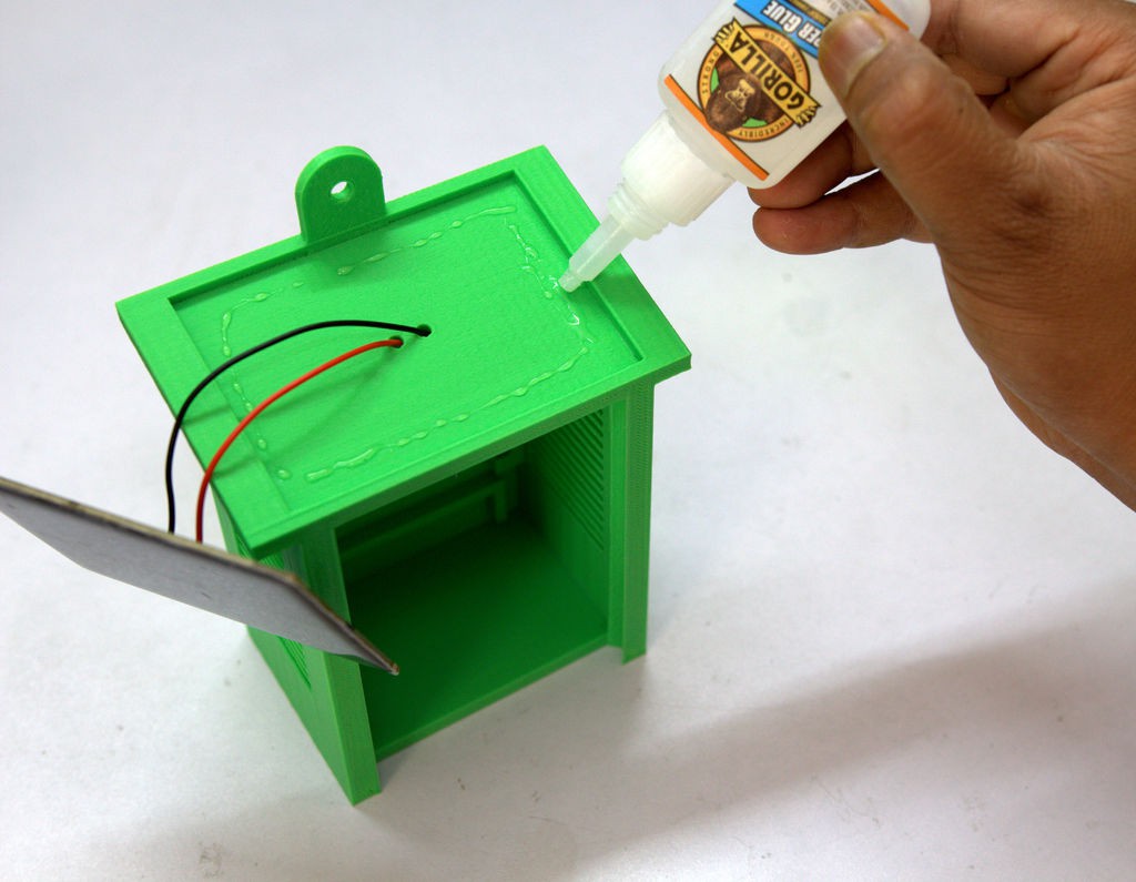
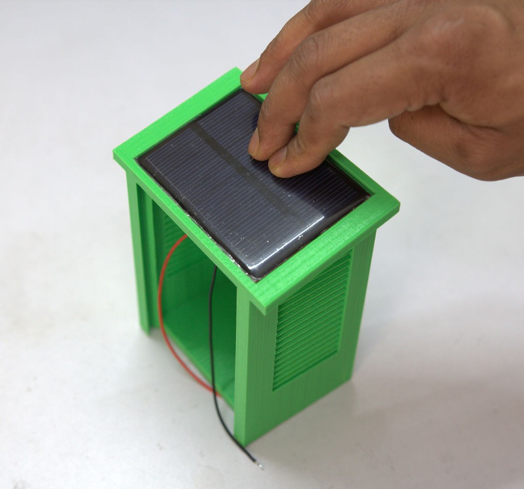
1. Installing the Solar Panel and Battery
Solder a 22 AWG red wire to the positive terminal and black wire to the negative terminal of the Solar panel.
Insert the two wires in to the holes in the roof of the main enclosure body.
Use super glue to fix the Solar Panel and press it some time for proper bonding.
Seal the holes from the inside by using hot glue.
Then insert the battery holder in to the slot at the bottom of the enclosure.
![]()
![]()
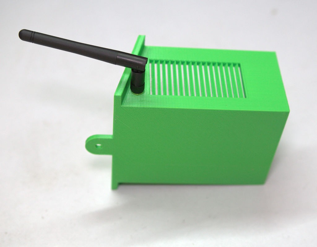
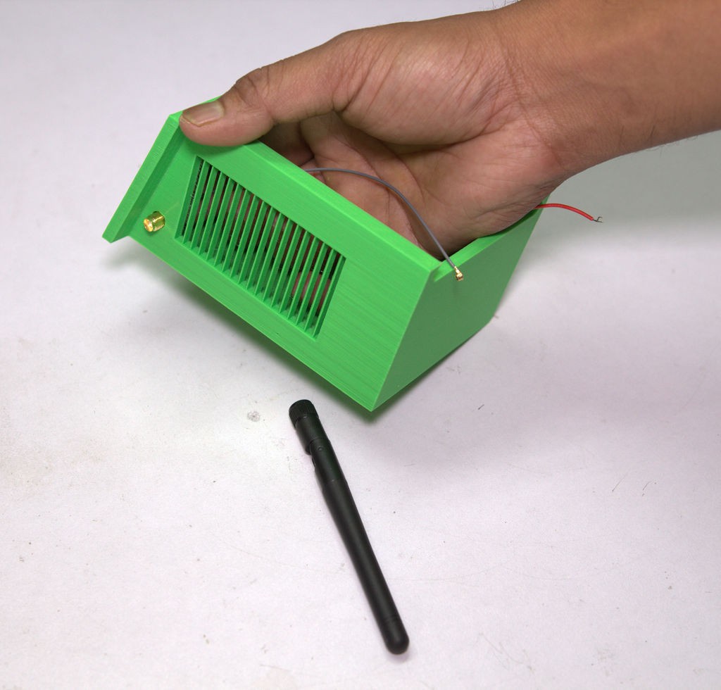
2. Installing the Antenna
Unscrew the nuts and washers in the SMA connector.
Insert the SMA connector in to the holes provided in the enclosure.See the image above.
Then tighten the nut along with the washers.
Now install the antenna by properly aligning with the SMA connector.
![]()
![]()
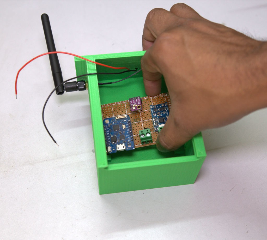
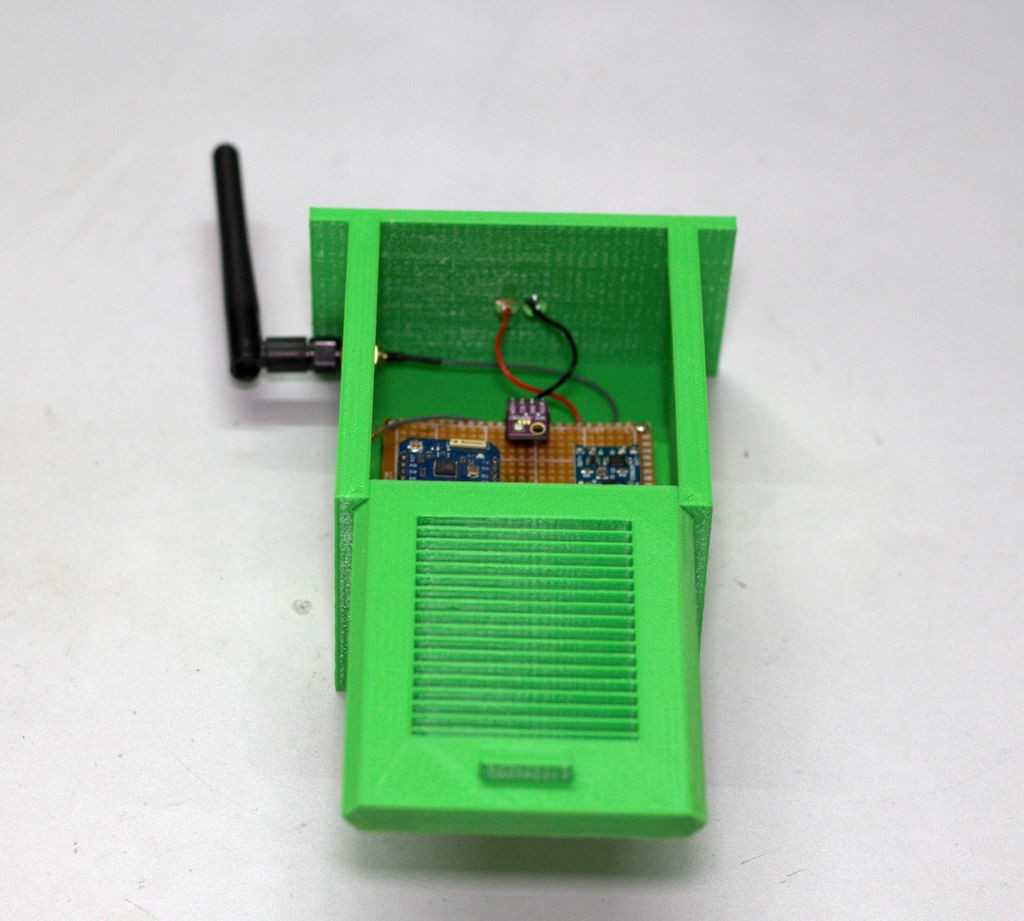
3. Installing the Circuit Board
Mount the standoffs at 4 corners of the circuit board.
Apply super glue at the 4 slots in the enclosure. Refer the above picture.
Then align the standoff with the 4 slots and place it.leave some to dry it out.
![]()
![]()
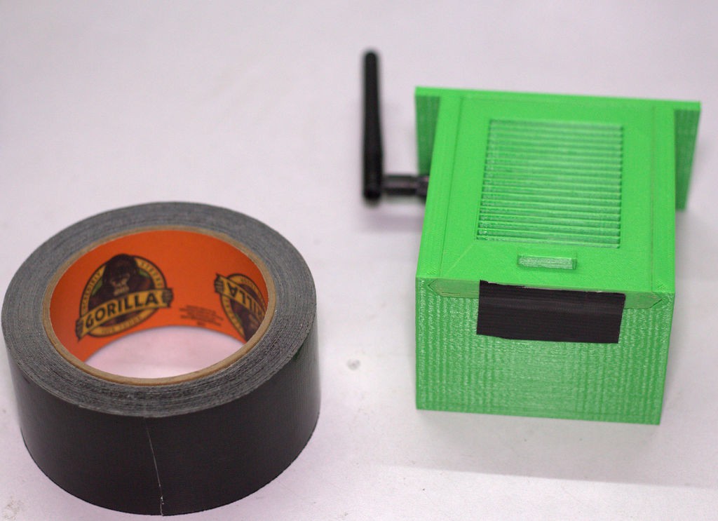
4. Close the Front Cover
After printing the front cover, it may be not perfectly fit to the main enclosure body.If it is the case, just sand it at the sides by using a sand paper.
Slide the front cover in to the slots in the main body.
To secure it, use duct tape at the bottom.
-
6Final Test
![]()
![]()
Place the device on sunlight, the red led on TP 4056 charger module will lit up.
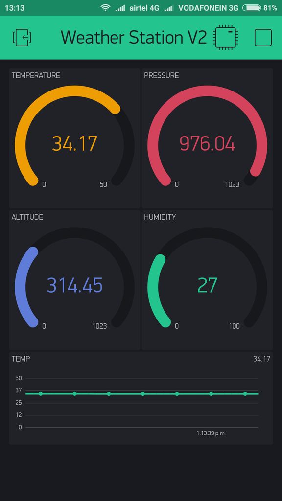
1. Blynk App Monitoring:
Open the blynk project.If everything is Ok,you will notice the gauge will live and the graph stat to plot the temperature data.
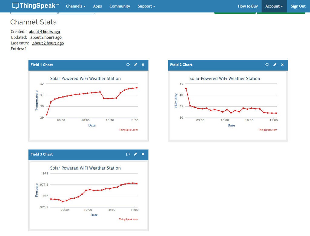
2. ThingSpeak Monitoring :
First open your Thingspeak Chanel.
Then go to “Private View” tab or “Public View” tab to see the Data Charts.
SOLAR POWERED WIFI WEATHER STATION
ESP8266 based Solar Powered wireless Weather Station

Discussions
Become a Hackaday.io Member
Create an account to leave a comment. Already have an account? Log In.
Looks great!
Just a couple of suggestions about the enclosure: it really should be white, and it should have a double-layer roof with good air flow between the layers. Google "Stevenson Screen".
Are you sure? yes | no