Dan Julio
-
tCam-Mini PCBs arrived!
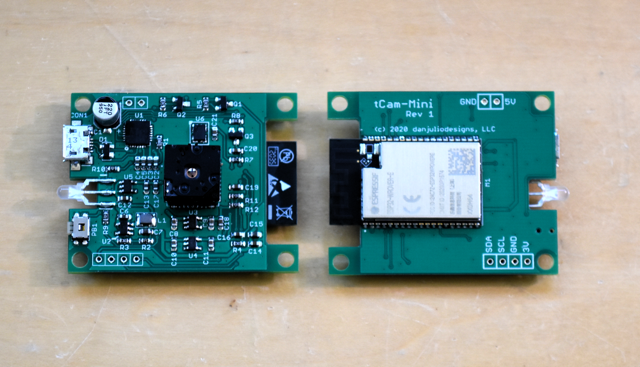
12/16/2020 at 18:10 • 0 commentsRev 1 of the PCBs arrived and seem to work great with one caveat.
![]()
I built up two boards. Both work, running the existing code, but one streams at a slower rate than the other. With this design I moved to modules using the v3 ESP32 chip and even after recompiling for that version the slow-down on one module persisted. I have noticed that one can get the FreeRTOS scheduler stuck in a pattern and I wonder if something like that is happening. Or perhaps something with one module's wifi interface. I'm going to add debugging code to see what part of the code is slowing down on one module.
![]()
The board has the ability for the ESP32 to reset the Lepton and I'll add code for that and do some clean-up. Then I should be able to post the code and hardware design on github.
Probably also eventually rev the board to add a reset button (useful to restart while the serial monitor is attached) and tighten up the cutout for the LED to make assembly easier (or hopefully find a cheap side-looker RG SMT LED with lens to poke through a 3D printed enclosure (also have to design the enclosure...)
-
tCam-Mini
11/30/2020 at 15:54 • 0 commentsA socially distanced Thanksgiving holiday finally gave me some time to work on tCam. Specifically I finished getting a new version that I’ve been working in spurts for a while called tCam-Mini debugged and running. I also put to bed some bugs and memory leaks in the companion desktop application.
![]()
My current idea is that there will be at least two models of tCam. The full tCam with a local LCD display and file storage and tCam-Mini designed to be a small, simple streaming thermal imaging camera. My work with the full tCam (now ported to the Fire Cam hardware for access to its 4-bit Micro-SD interface) shows that the ESP32 probably lacks sufficient horsepower to simultaneously display, record and stream over wifi the full 8.7 frames-per-second from the Lepton. I plan to use two ESP32 chips for the full tCam and this will be the subject for a future project log. However one ESP32 is sufficient for a small camera that forgoes the LCD and local file storage.
All tCam cameras will work with the desktop application. It will grow to include the ability to graph the temperature of selected points in the image over time (I intend to use this feature to monitor temperatures on circuit boards). I’ve also started to contemplate another computer application. This one will be a recording web server, hopefully with the ability to recognize some thermal signatures so the cameras can be left running and pictures or videos recorded when “interesting” things happen. Access will be from any web browser.
![]()
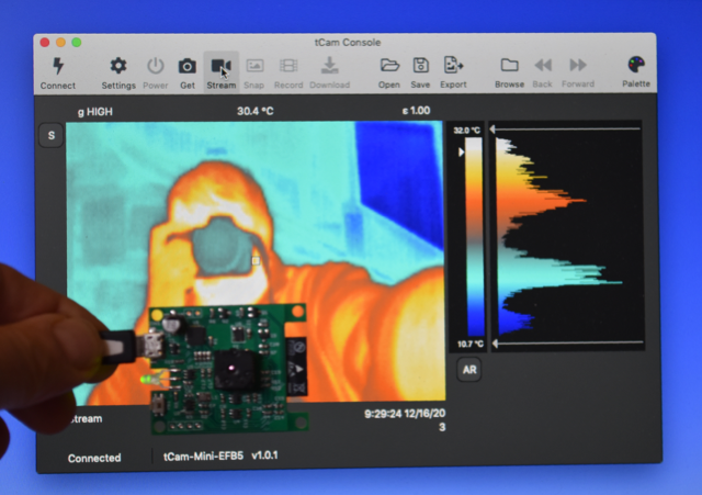
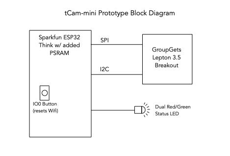
tCam-Mini acts as an access point by default but can be put on another network using the utility. It can return single pictures or stream images. It is based on the code from the full tCam code-base although some of the code was optimized for operation as a streaming camera. The code base has also been ported to the IDF 4.0.2 release. Although I am getting the full frame rate from the Lepton in one task, I can only stream 5-6 frames-per-second over wifi from another. I hope further debugging will improve that number.
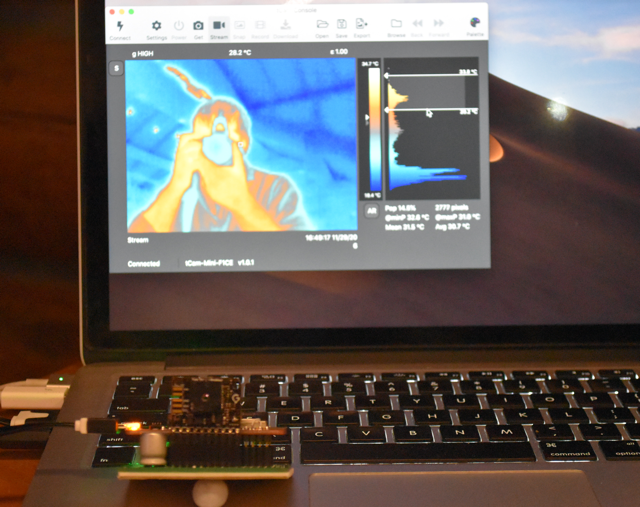
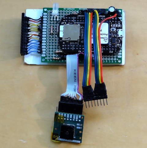
The prototype is based around a Sparkfun Thing dev board. Initially I hoped that I could get by without extra RAM but found I couldn’t fit the necessary buffering in the limited on-board space so I bodged a PSRAM on top of the module.
![]()
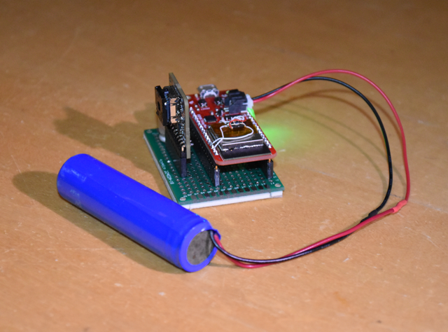
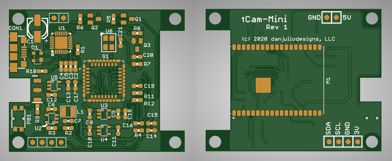
Over the holiday I also laid out a circuit board for tCam-Mini and plan to mate it with a 3D printed enclosure. It uses a WROVER ESP32 module and forgoes the Lepton breakout board to include the Lepton circuitry directly on board. Aside from the Lepton, single unit price for the components and PCB is about $20. I hope to build up a unit in December.
![]()
Ultimately - after further optimization and cleanup - tCam-Mini will be open sourced. I may try to sell them on Tindie but pricing will be tricky as I currently pay around $200 for each Lepton. That makes the camera fairly expensive with even only a moderate mark-up. Research on quantity pricing for the Lepton is in order…
-
tCam video
06/24/2020 at 15:58 • 0 commentsI entered tCam into a contest sponsored by Tech Briefs Media Group. Here's a video made for the entry that shows the camera in operation.
-
tCam progress and some setbacks
06/23/2020 at 05:08 • 0 commentsThe gCore-based camera has now become tCam and has probably outgrown its gCore base. I added code to enable Wifi and a json-based command processor for remote access and control with a command structure like FireCam.
![]()
Two interesting side-effects surfaced. There is a little noticeable noise in the data from the Lepton when the esp32 is acting as an access point (but not when it is client). The LCD controller also gets confused on occasion when Wifi is enabled and the Lepton performs a FFC. I suspect the current required on the 3.3V rail exceeds the ability of the gCore TPS63051 converter and the voltage sags enough to confuse the LCD controller. I suspect this will be an even bigger problem when adding support to read and write data to a Micro-SD card.
Probably will need to design a new PCB with a better power supply.
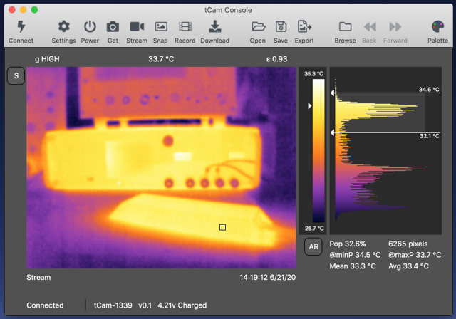
In the meantime I also wrote the first version of the desktop application that will be used for remote viewing, analysis and file management in the camera.
![]()
![]()
Eventually I want to support for multiple selectable sense regions and a plotting module so I can monitor temperature changes over time (e.g. monitoring several areas of PCB).
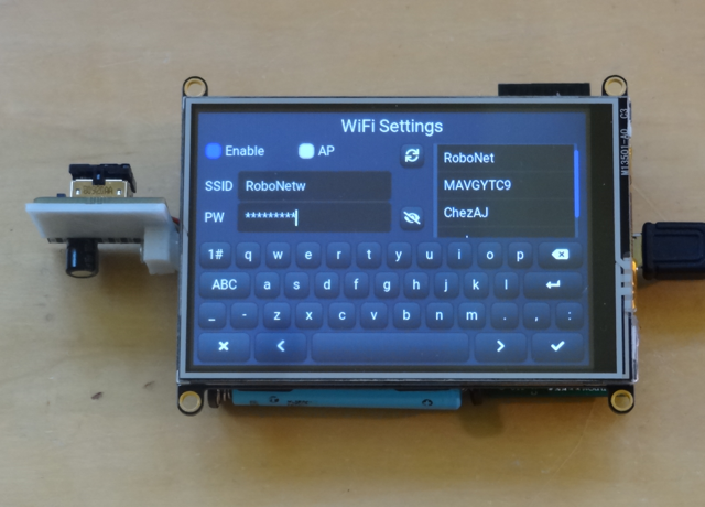
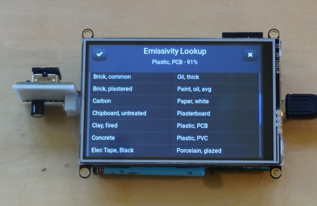
I also added a new screen to tCam to allow setting emissivity from a list.
![]()
-
FireCAM
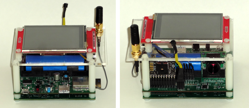
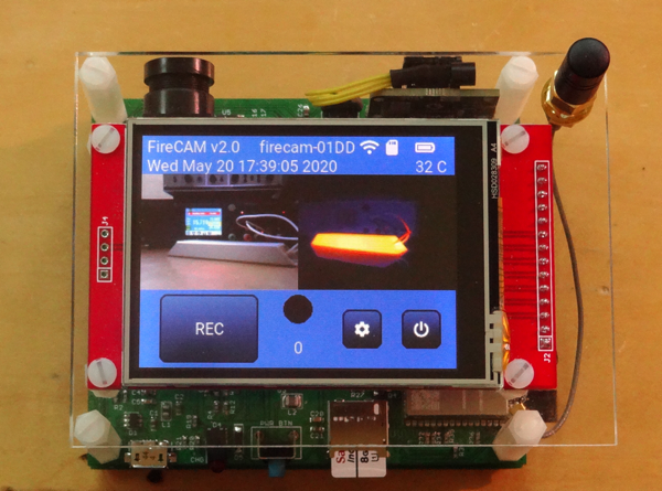
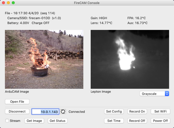
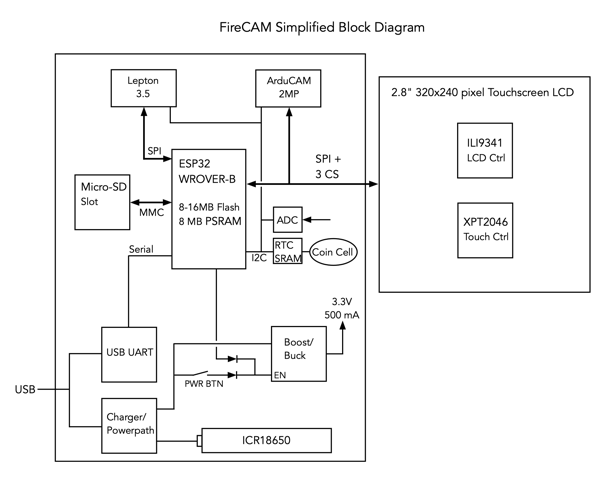
05/22/2020 at 18:45 • 1 commentMy work with the Lepton lead to an opportunity to design a timelapse camera for a scientist working for the U.S. Forest Service Southern Research Station. He plans to use the radiometric (temperature) data from the camera to study forest fires. He also requires visual image data. The result is a device called FireCAM based around the Lepton 3.5, an ArduCAM 2MP, ESP32 and GUI using LittlevGL. The project also includes a simple utility program for Mac or Windows to control the camera via a WiFi interface. Because it is a government project I was able to release the complete design as open-source. It can be round on github. Images are stored as json-formatted files (or sent via the wireless interface) which leads to all kinds of interesting possibilities I think.
![]()
![]()
![]()
![]()
-
A change in plans
05/09/2020 at 20:11 • 0 commentsMy poor thermal imaging camera has been neglected while life went on and my time was spent elsewhere. I even designed a thermal imaging time-lapse camera for a client was based on the ESP32. As I worked on that project I became more disillusioned with my Pocketbeagle linux camera solution, primarily because of the long boot time for linux. In addition the PRU pipeline would have to be reworked to support 16-bit radiometric data (it currently only supports 8-bit AGC data) and the 320x240 pixel LCD display seemed constraining. I wanted to display a reasonable size image along with some controls. The easiest size image to make is 320x240 because it requires a simple doubling of the Lepton's 160x120 pixel output. However this leaves no space for controls unless they sit on top of the image.
Long story short, I ended up deciding to remake the camera using an ESP32. To that end I designed an ESP32 development board called gCore (documented here) that uses a 480x320 pixel display and started work on a new camera design with the Esspressif ESP-IDF and LittlevGL.
![]()
The hardware is pretty simple. A Lepton 3.5 connected to gCore via a swivel mount comprised of two simple 3D printed mounts and a screw, and a Maxim/Dallas DS3232 RTC clock with 236 bytes of SRAM for settings and parameter storage. The RTC is powered directly from the LiPo batteries using its own ultra-low quiescent current LDO and communicates over I2C.
Firmware is a work-in progress. At the moment the camera functionality is pretty much done. It supports both radiometric and AGC modes. The radiometric mode allows extraction of image temperature anywhere. AGC can be used for higher image quality. There's a spot meter and a bunch of palettes. The Lepton's image can be smoothly interpolated up to 320x240 pixels. I plan to add the ability to store images or videos on an MicroSD card. However instead of using an image format, such as png or jpg, I will store json-formatted files with the raw radiometric and telemetry data from the Lepton and other camera meta-data. This will allow generating images or performing thermal analysis on images later. I also plan to add a wifi-based command interface for talking to an application for display, control and analysis of images. I haven't figured out how to do this yet but I'd like the application to be able to further calibrate the camera for more accurate readings (Flir claims at best +/- 5C accuracy with a stock Lepton).
![]()
I haven't completely forgotten the Pocketbeagle camera. I think I'll turn it into a web cam with a basic interface on the LCD and remote viewing through a web interface. Not a huge amount of code I hope.
-
littlevgl GUI running
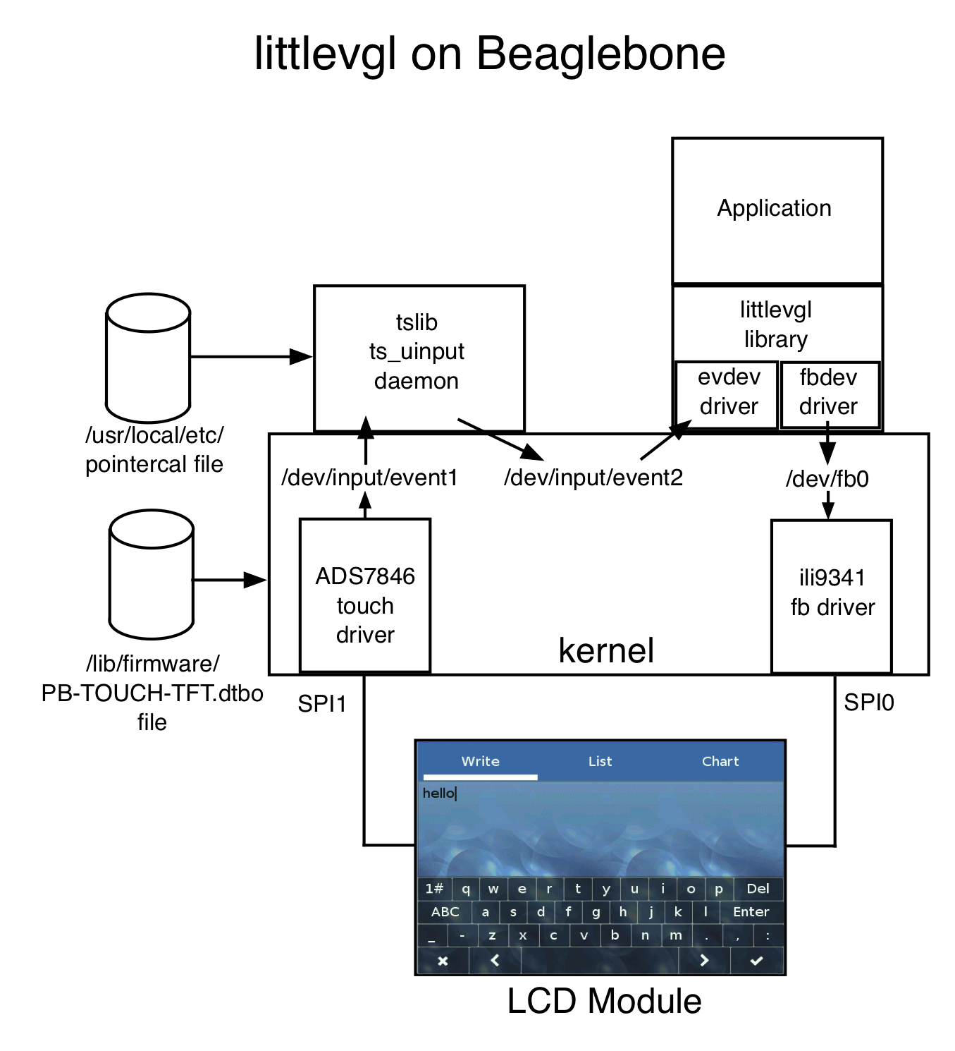
07/26/2019 at 04:59 • 0 commentsI want to see if the littlevgl GUI library can be used on my camera to provide a GUI on top-of and around the video stream. One great thing about this library is a well-defined hardware abstraction layer that already includes support for the linux frame buffer and linux touchscreen event driver. I already had the frame buffer running on my LCD module and I finally figured out how to use the LCD's resistive touch controller with new device tree entries. This allowed me to quickly get the littlevgl demo program running.
![]()
littlevgl also has a direct SPI-based driver for the TSC2046 resistive touch controller IC that I originally thought I might use. Typically this would be used on a bare-metal embedded system (such as an Arduino or Teensy). However as I researched it became clear that using the built-in linux touchscreen driver would be superior because I could make use of tslib's ability to provide calibration and de-jitter for the resistive touchscreen. I did have to make a hardware change and add the pendown IRQ to a GPIO (GPIO27/P2.19) on the Pocketbeagle so my wiring diagram is updated.
![]()
Architecturally the system looks as follows. The tslib utility program ts_calibrate is run before the application to generate the pointercal file used subsequently by the daemon.
![]()
The resistive touch screen works fairly well and will probably be sufficient for my application but we are spoiled by our capacitive touch screens and using something like the Adafruit Cap Touch LCD Module would eliminate the need for tslib and provide much better control at a substantial increase in cost (USD14 -> USD45).
The updated device tree files, uEnv.txt and configured littlevgl library and demo are available on github. I also got this running on a Beaglebone Black. Even if you never build this camera perhaps the ability to have a sophisticated GUI running on a cheap LCD without needing the entire window system might be useful.
-
Pocketbeagle Camera Design
06/07/2019 at 20:44 • 0 commentsThis poor project has languished too long. I apologize if anyone has been waiting for the info I promised months ago. I have actually used the camera but the documentation was waiting to be pulled together. As well as quashing a niggling bug in the PRU VoSPI code that prevented it from properly syncing with the Lepton on occasion. Over the last couple of weeks I finally had some spare time and updated my github repository with a detailed description of the camera, the modifications to the Solar Pi Platter, enclosure design and initial software. Please head over there to see a bunch of new info in the "pocketgbeagle" directory describing the camera build.
Next up will be to start on what I hope to be the real application software for the camera including a touch interface for the LCD display, and remote access through a web browser as well as custom desktop application. I'm going to try to make a modular architecture so that parts of the code can be used on existing Beaglebone and Pocketbeagle computers with the Lepton 3.5 without having to build a bunch of hardware if one doesn't want too - for example to make a thermal-imaging webcam.
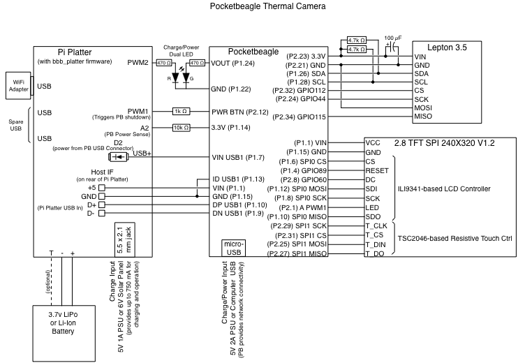
Here's the schematic of the camera.![]()
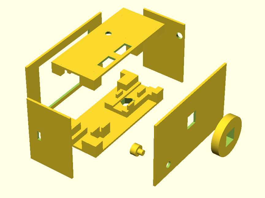
And an exploded view of the openSCAD designs for the 3D printed case.
![]()
The existing program, pru_rpmsg_fb, used to display the video stream on the LCD display and necessary support files for the Pocketbeagle are also in the respository.
-
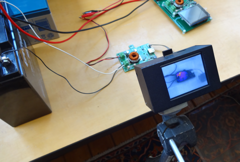
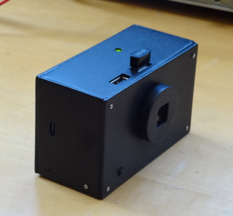
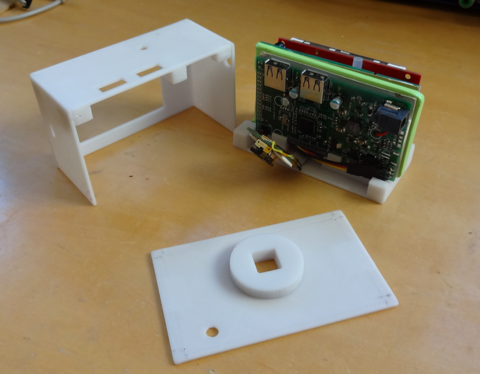
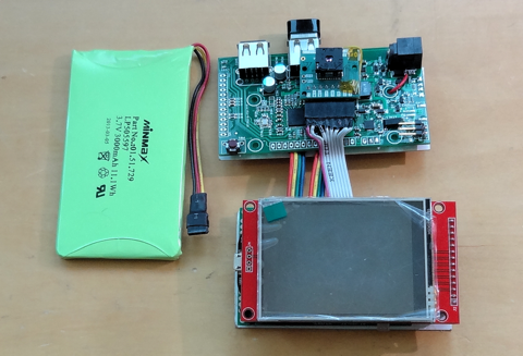
An external PMIC makes for a boxy camera
02/19/2019 at 05:22 • 0 commentsBut I have a camera now! After the disappointment with the Pocketbeagle's built-in power-management system I decided to just hack my own Solar Pi Platter to act as a battery charger, power supply, RTC and USB Hub and then 3D printed a case. After a lot of spray painting I now have a brick of a camera!
![]()
This is a quick update. In case anyone is interested I will shortly update github with the schematic, new code for the Pi Platter and the OpenSCAD/STL files for the enclosure. Currently it's just running the existing PRU code ported to the Pocketbeagle.
![]()
![]()
![]()
![]()
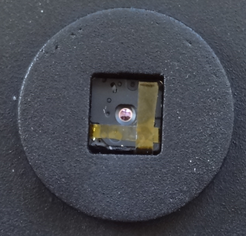
I had one huge panic. I was manipulating the PCBs and bumped the Lepton on the desk. The shutter came apart and I almost did too. Fortunately I didn't lose any small parts. But it didn't go back together in a functional state. The shutter stuck whenever it closed. After contemplating another $300 I started hacking. Finally removing an internal shield and taping the whole thing back together yielded a functional part again. At least for now.
![]()
-
Beaglebone PMIC - so close and yet so far
12/21/2018 at 04:57 • 2 commentsThe Beaglebone boards have an additional capability, aside from the PRUs, that differentiate them from many other SBCs like the Raspberry Pi. They have a true power-management controller (PMIC) that generates all the various on-board DC voltages and supports dual input voltage sources (DC in and USB in) as well as a 3.7v LiPo or Li-Ion battery including a charger. In addition the PMIC, a TI TPS65217 designed specifically for the AM355x processor, can be configured to supply power to the AM355x built-in real-time clock while the system is powered down and sports a power button that interacts with the kernel for controlled shut down - features that are perfect for a portable device like a thermal imaging camera.
Or at least in theory. It turns out that a hardware bug in the first revision AM335x processor and decisions about how to wire the PMIC to the processor in the original Beaglebone Black made it so the "RTC-only" mode would never work, and under certain circumstances could actually damage the processor (a current leakage path through the processor to the USB serial interface). However based on a lot of reading of various specs and errata I ascertained that the pocketbeagle shouldn't be at risk so I was excited to see how it ran on battery power (the battery signals are helpfully broken out).
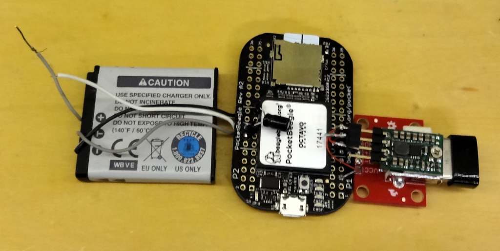
![]()
I connected an old camera battery to the pocketbeagle and added a 5V step-up boost converter to power a USB WiFi dongle attached to the pocketbeagle's host USB port. The PMIC wants a temperature sensor in the battery back and the camera battery had the right kind (10K). Unfortunately the PMIC doesn't generate a 5V out when running on the battery so the boost converter was necessary. I noticed that the 3.3V output was only powered when the pocketbeagle was turned on so it sources the boost converter. Success! Or at least I thought at first. The pocketbeagle ran happily from the battery with a reasonable current draw (< 200 mA w/ WiFi). And it charged the battery too when plugged in via the USB Micro-B interface - at least while the system was running. The problem came when the system was shut down. Charging stopped. This is hardly ideal for a portable device as not only do we expect them to charge while off but turning the system off makes more power available for battery charging.
The TI PMIC has the capability to charge the battery when its DC output supplies are disabled (system off) but clearly something was disabling that when the system was shut down. I dug into kernel source with help from a friend at my hackerspace and finally figured out the sequence of events that prevented charging when the system was shut down. It turns out that the device driver for the PMIC (tps65217.c) configures the PMIC to enter "off" state when powered down instead of "sleep" state which would let it charge the battery. A fuller explanation is documented in the pocketbeagle's google group.
I thought this was good news because the driver configures the PMIC during probe at boot time and the PMIC can be reconfigured via its I2C bus after the system boots. I tried it. Success again - kind of. The battery charged after the system shut down. But there was also a ~15 mA load on the battery from the switched-off system - enough of a load to discharge a battery pretty quickly if the system was disconnected from the charger. Unfortunately the pocketbeagle uses an Octavo system-in-a-package and I couldn't understand what could be causing the additional discharge. Fortunately Octavo replied to a question on their support forum. When the PMIC is configured to "sleep" mode enabling battery charging, it also enables one LDO regulator that is designed to feed the RTC input on the processor. Octavo also connected another power-rail (plus an enable to the 3.3V LDO) to that output per TI's spec and the quiescent current is huge, at least 15 mA huge. Octavo claims that a future version of the chip, one with an on-board EMMC, will not have the same connection and may work. But this device will not be on the pocketbeagle so my idea of using the PMIC to charge the battery was dashed.
Well, there is one work-around I thought of. I can add an external circuit or micro-controller to handle the on/off power button. It will toggle the pocketbeagle's power button input when the system is shut down but it only signal an application running on the pocketbeagle via a GPIO when the system is up and the user wants to turn power off. This would let the application shut down the thermal imaging app and display to reduce power consumption while still leaving Linux running until the battery is charged. Then the system can fully shut down via some additional handshaking between something running on the pocketbeagle and this additional circuitry. I still have to add an external RTC since I want the system to know the right time so it can timestamp pictures saved to non-volatile storage. Plus an external boost converter for USB (WiFi). It is a not-insignificant amount of additional circuitry.
In the end I decided I will re-use the design I did for a gadget called the Solar Pi Platter I designed to power the Raspberry Pi Zero from a battery. It provides power control, automatic power-path switching, battery charging, and a RTC as well as a (power-hungry) USB Hub. I am going to modify its firmware slightly to utilize the beaglebone's power-control input and sense when Linux has shut down before killing power turning the Pi Platter into a Beaglebone power solution.
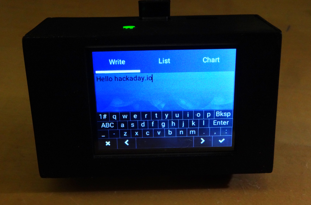
Next up is to put together a prototype using the pocketbeagle, a hacked Pi Platter, battery, the Lepton, and a touch LCD. A change from last time, based on playing with the littlelvg graphics library, is a move back to a resistive touch panel controller. The littlevgl library has a on-screen keyboard that will be nice to use when entering WiFi credentials but it turned out to be really hard to use with the capacitive touch panel controller (tiny buttons, big fingers). I think it might actually be easier to use with a resistive panel and a plastic stylus. We'll see.
It's a shame the power subsystem on the beaglebone's isn't slightly more capable. While it will work as a UPS, it's going to be hard to make a battery powered gadget without going through extra hoops.
Lepton 3.5 Thermal Imaging Camera
Documenting my experiments with the FLIR Lepton 3.5 thermal imaging camera.