Dan Julio
-
Finally! PRUs in the picture
12/07/2018 at 04:54 • 0 commentsMy post-holiday obsession continued until I am - finally - reading data from the Lepton using both PRUs in a Beaglebone Black. Given how - relatively - easy it is to use the PRUs I have to confess I pored over a lot of web postings before figuring it out. I'm not even the first person to document using the PRUs to read a Lepton camera. That honor, as near as I can tell, goes to Mikhail Zemlyanukha who used a PRU and a custom kernel driver to get image data on a 4.9 kernel system. Unfortunately as I found out, programming PRUs is an evolving paradigm and what worked in the past, including Mikhail's code and old methods such the UIO interface no longer work on current kernels. Finally I found Andrew Wright's tutorials and started reading TI's remote processor and rpmsg framework source and started to get code running on the PRUs.
![]()
Although it was a slog, I have been converted. I think the real-time possibilities offered by the PRUs in close cooperation with the Linux system are amazing. The PRU is my current favorite embedded micro-controller because it has easy access to an entire Linux system without the baggage of any OS - and on something as small and cheap as the pocketbeagle.
In case the following looks TL,DR; the code is the github repository.
Failed First AttemptI was daunted trying to get Mikhail's kernel driver running on my 4.14 system but understood his use of one PRU to capture packets and send them upward to user-land. I also successfully built and ran the rpmsg "hello" demos. The rpmsg system is built on top of the kernel's virtio framework to allow user-land and kernel processes to talk to remote devices (e.g. embedded cores or co-processors). TI has adopted it as the "official" mechanism for their OMAP processors to talk to the on-board co-processors (including the PRUs and the power-management ARM core). It is probably used in every smart phone as I found Qualcomm's contributions to the source. The kernel's rpmsg driver makes a co-processor available as a simple character device file that user-land processes can read or write just like any other character device.
So I put together a simple program that got non-discard packets from the PRU and sent them to the kernel using rpmsg. The PRU bit-banged a simulated SPI interface at about 16 MHz, buffered one packet's worth of data (164 bytes) and then copied it to kernel space via rpmsg. My idea was to essentially replace the calls to the SPI driver in earlier programs with a call to the rpmsg driver to get SPI packets through it via the PRU. I did have the sense to try to filter out discard packets but still, BOOM. My BBB was brought to its knees by a message from the PRU about every 95 uSec (basic packet rate at ~16 MHz SPI + a very quick buffer copy - the PRUs are excellent at pushing data to main system memory). They system was 100% pegged, unresponsive and my application seemed to be getting about 1 out of 100 packets.
I didn't know it at the time but I was way overrunning the capability of the rpmsg facility and the kernel was bogging down trying to write an error message for each rpmsg from my PRU (that was overflowing its virtio queues) into several log files. I saw later the hundred megabytes of log files that had accumulated. The poor micro-SD card.Taming rpmsg
Clearly I had to reduce the frequency at which messages were sent to the kernel driver to deal with - and also increase the amount of data sent at a time. Quickly I found that the maximum rpmsg message size is 512 bytes, of which 16 bytes are used for message overhead. It took a long time - this stuff doesn't seem to be documented anywhere - to understand that the kernel could manage a maximum of 32 entries in a queue for messages for one rpmsg "channel". At least I had some parameters to work with. The Lepton is fussy about making sure that the VoSPI interface keeps up with its true 27 fps rate (even though, because of US government restrictions, it only outputs 9 fps of actual image data). Losing sync causes it to be unable to output good data at all. The easy way to manage this is to dedicate one PRU to reading the Lepton and the other PRU can manage pushing data to the kernel.
![]()
The system I came up with has PRU0 reading packets, discarding any ones it can, and writing packets it thinks are good, or potentially might be good (another quirk of the Lepton VoSPI is that we don't know if the first segment's worth of packets is real until the 20th packet), to a circular buffer held in the 12K shared memory buffer between the PRUs. PRU1 is responsible for accumulating more than one packet's worth of data from the circular buffer and sending it upward through the kernel to the user process consuming frames. It does this slowly enough not to overwhelm the kernel, but fast enough to keep up with the realtime data requirements. Additionally, to reduce the data size, I enable the AGC mode on the Lepton so that it outputs 8-bit data words (1/2 of each 16-bit word in a packet) reducing the size of a frame to 19200 bytes. This is still bigger than the shared buffer so the timing of the the PRUs has to be set so that PRU1 doesn't read data too fast to read ahead of where PRU0 is writing and PRU0 doesn't write it too fast to overrun where PRU1 is reading. The deterministic nature of the PRUs is useful here. Instruction execution timing is set and data memory accesses have a small variability based on activity of other devices (other PRU and main ARM CPU).
PRU0 reads one 164-byte packet every 128 uSec. It requires about 90 uSec to read the data and write it to the shared memory. It writes 80 bytes (only the low 8-bits of every data word). It restarts its acquisition process whenever it sees packets out-of-sequence and it notifies PRU1 when it has seen the first 20 packets of segment 1 (the first opportunity to know we are probably in a good frame).
PRU1 accumulates six packets worth of data (480 bytes) and adds a sequence number to create a single rpmsg message every 1024 uSec once it's been triggered by PRU0. It takes 40 message for a complete frame over 41 mSec. A new frame's worth of data is generated about every 112 mSec and both the kernel and a user-land process are able to easily keep up with the full 9 fps data flow for only a couple of percent of main processor time.
PRU0 can tell PRU1 to abort a transfer if it sees a bad packet sequence and then PRU1 informs the user-land process that the frame it is reading is bad with an illegal sequence number. The user-land process uses the rpmsg facility to enable the VoSPI interface by sending a '1' to PRU1 and disable the interface by sending a '0' to PRU1.The PRU shows up as /dev/rpmsg_pru31 to the user-land process and normal read and write operations are used to receive and send data. The remoteproc framework is used to load firmware into the PRUs and start and stop them. The current BBB Debian distributions include the PRU C-compiler and support libraries, including rpmsg, so it isn't a chore to setup a compile chain for the PRUs anymore. The I2C interface is used to configure the Lepton. prudebug is invaluable (and shows how to just directly map and manipulate PRU memory from user-land).
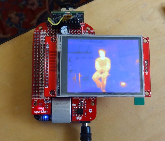
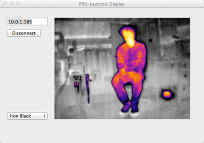
The github readme has more detailed technical information.I ended up writing two separate demo applications. The "pru_rpmsg_fb" application reads frames from the lepton in one thread, pushes them into a circular queue of frames, and reads them out, through a colormap into RGB565 data written directly to the LCD framebuffer in another thread. The fb access is fast(!) and the two threads are probably unnecessary. The "pru_leptonic" is yet another take on Damien Walsh's leptonic program and uses the PRU pipeline to feed his zmq-based socket server. You can connect his web server as a client or the "zmq_fb" program which reads from a socket and updates the frame buffer, or even my PRU-Leptonic demo on the Mac which reads across the network connection.
![]()
Performance
Here's the output from "top" while running both the "pru_leptonic" network server, the "zmq_fb" network client program to display images on the local LCD and a connection from the PRU-Leptonic program running on my Mac also displaying the images. Both displays running at the full 9 fps.
top - 04:17:48 up  4:32,  3 users,  load average: 0.92, 0.76, 0.69
Tasks:  97 total,   1 running,  67 sleeping,   0 stopped,   0 zombie
%Cpu(s)  4.4 us,  4.8 sy,  0.0 ni, 90.1 id,  0.0 wa,  0.0 hi,  0.7 si,  0.0 st
KiB Mem :   495024 total,   288804 free,    70552 used,   135668 buff/cache
KiB Swap:        0 total,        0 free,        0 used.   408160 avail Mem

  PID USER      PR  NI    VIRT    RES    SHR S %CPU %MEM     TIME+ COMMAND
 1158 debian    20   0   39672   3560   2880 S  2.6  0.7   2:37.42 pru_leptonic
 1184 debian    20   0   22164   3388   3000 S  2.3  0.7   0:03.02 zmq_fb
  945 root     -51   0       0      0      0 S  2.0  0.0   3:05.48 irq/74-remotepr
 1201 debian    20   0    7052   2748   2232 R  1.3  0.6   0:01.01 top
Next stepsI bought a pocketbeagle and have been playing around with it, especially to see if its built-in PMIC can be used to manage power in a battery-powered device. It doesn't look hopeful but I am still experimenting. I want to make the final camera based around it and a WiFi dongle, the Lepton 3.5, a short-range IR (NOIR) camera and bright IR LED for night vision and an Adafruit capacitive touch 2.8" ILI9341-based 320x240 pixel LCD, the whole thing powered by a 2000 mA LiPo battery.
On the software side I downloaded LittlevGL as a possible light-weight GUI that can ride directly on top of the linux frame buffer. And I will contemplate writing my own linux kernel driver to work around some of the limitations of rpmsg and perhaps have a driver that can support all of the Lepton's video modes. But that my have to wait too...
Correction to my understanding of the Lepton with RadiometryIn the past I thought one had to disable the Radiometry function to enable AGC. However it seems that one only has to disable the TLinear function (which returns 16-bit absolute temperature values for each pixel), while leaving Radiometry operating. This allows using the spot meter function with AGC. I will update my Teensy 3 lep_test10 sketch to include this new understanding. It only took the millionth reading of FLIR's documentation for me to intuit this was possible.
-
[Finally] Playing with Beaglebone Black
11/24/2018 at 17:34 • 0 commentsThe American Thanksgiving holiday finally gave me some time to attend to this project again. I even planned to use the Teensy version of the camera to look at my daughter's house to help her and her husband identify where it was losing heat but sadly I left it at home in a rush to get out the door for the holiday.
My end goal has been to make a wifi-enabled camera using the Beaglebone Black with one or both of its PRUs handling the Lepton VoSPI data stream to get the full 9 FPS out of the camera and be able to view it and access photos remotely. I looked into using the ESP32 like Damien Walsh did and although it is an incredibly capable embedded system, I ultimately decided that I want a full Linux environment to build the camera application on. Experiments with the Raspberry Pi show that it's hard for a user process to keep up with the VoSPI data flow - although as someone from my Makerspace pointed out, it's quite possible that applying the Linux real-time patches might make that feasible (something to be investigated at a future point). The PRU subsystem was the first solution that occurred to me but I also investigated writing a kernel driver or seeing if the v4l2 project supported the lepton. All of the solutions are intimidating to me because of the need to dive into some moderately complex low-level linux programming so it's been easy to put off getting started.
I have an old 7" 4D-systems Beaglebone Black touch LCD cape that I thought I'd use for the camera display but over time have decided it's too bulky and power hungry. I also have become interested in the Pocketbeagle board because of its small size and lower power consumption - characteristics better suited for a portable camera. This lead to an investigation of using the Linux framebuffer driver and one of the ubiquitous ILI9341-based small LCDs using a SPI interface. Because I also want to support another camera that also requires an SPI interface (for near IR - or night vision) I finally made the commitment to using the PRUs for the Lepton (over a low-latency software solution) because I can dedicate the two built-in SPI interfaces on the Pocketbeagle to the LCD and Arducam near IR camera.
Making that commitment, and the time afforded by the holiday, finally got me moving on building a prototype.
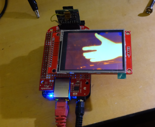
![]()
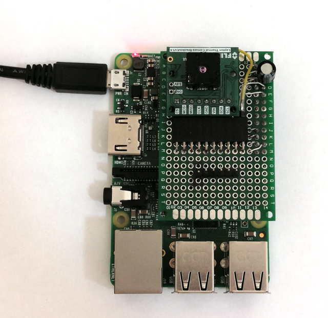
The first prototype simply connects the LCD to SPI0.0 and the Lepton to SPI1.0. I am taking things one step at a time, first getting the Linux FB talking to the LCD and then getting some user-space code talking to the Lepton. About twelve hours of hacking later (most spent figuring out how use the Device Tree system on the Beaglebone Black to configure IO and enable the frame buffer) yielded a hacked version of leptonic directly driving the frame buffer. It works pretty well. I'm not sure what the frame rate is but it's definitely higher than the 4.5 FPS I get on the Teensy 3.2 test platform. It also occasionally stutters and gets confused reading the VoSPI datastream resulting in a garbage display for a frame. The hacked code is pretty ugly - near midnight I was in full-on hack-hack-hack mode - so I'm not sure I'll post it (although I'm happy to share if you'd like a copy). There's also a version that can send packets over the ZMQ network interface. However I'm posting relevant parts of the /boot/uEnv.txt file below and a link to the Device Tree source file that finally worked to make my LCD a display (thanks Bruce!). I modified the dts file to fit my rotation (90°) and lowered the frame rate some (since my practical limit is 9 FPS).
The following uEnv.txt changes will make sense if you've messed with the Beaglebones much and maybe they'll help someone trying to get an ILI9341-based LCD to work as a display.
#uboot_overlay_addr4=/lib/firmware/.dtbo
uboot_overlay_addr4=/lib/firmware/BB-SPIDEV1-00A0.dtbo
#uboot_overlay_addr5=/lib/firmware/.dtbo
#uboot_overlay_addr6=/lib/firmware/.dtbo
#uboot_overlay_addr7=/lib/firmware/.dtbo

###
###Custom Cape
dtb_overlay=/lib/firmware/TFT-ILI9348-SPI0.dtbo
Here are the two overlays. The first (re)enables SPI1 for the Lepton (this shows up as /dev/spidev2.0 and /dev/spidev2.1). The second was compiled from my modified copy of Bruce's Device Tree source file to enable the LCD FB. I made the file using the following command.
dtc -O dtb -o TFT-ILI9348-SPI0.dtbo -b 0 -@ TFT-ILI9348-SPI0.dts
sudo mv TFT-ILI9348-SPI0.dtbo /lib/firmware
###Disable auto loading of virtual capes (emmc/video/wireless/adc)
#disable_uboot_overlay_emmc=1
disable_uboot_overlay_video=1
This disables HDMI video so that SPI1 is available.
cmdline=coherent_pool=1M net.ifnames=0 quiet spidev.bufsiz=16384
Finally increase the SPI1 buffer size so we can read an entire segment at a time from the Lepton (the default Beaglebone SPI buffer is 4096 bytes).
It's scary to see an entire day's work boiled down to just a few lines in a text file.
Now to try to get something running on a PRU...
-
Pi Zero experiments + app experiments
08/24/2018 at 07:03 • 0 commentsI finally got around to trying the lepton on a Pi Zero. Not a good outcome but an interesting result. The interrupt-driven version of leptonic failed miserably. It could not keep up with the VoSPI data. However Damien's original version did work partially. It could get data but constantly lost sync and frequently returned garbled data. I didn't look at the SPI bus on a scope to make sure there was nothing funny going on there but it doesn't seem the Pi Zero is well matched - at least for user-space programs - with the Lepton 3. No doubt a kernel driver would work but that's beyond me at the moment.
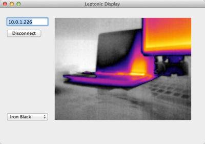
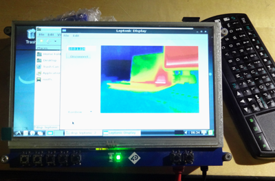
I have also been hacking around at the application level to make sure that the cross-platform application development tool I use (xojo) is up to the task and could be integrated with the zeromq messaging library since it makes working with sockets very simple. Much more success there. Here's a test app running on my Mac and also on a Beaglebone Black simultaneously getting a feed from the leptonic server on the Raspberry Pi 3. Getting the full 9 fps from the lepton. I think I'm ready to try to use the PRUs as a VoSPI engine.![]()
![]()
-
Working with a Pi
08/17/2018 at 16:12 • 0 commentsUltimately I'd like to create a solution that comprises a linux daemon communicating with the camera and a socket-based interface to a display application for local display as well as web server for remote display. The Beaglebone Black solution will make use of the VSYNC signal to synchronize transfers. Before tackling the BBB's PRU coding I think it will be a good idea to get the daemon interface running. Since this architecture is like Damien Walsh's leptonic project, it made sense to play around with his code on a Raspberry Pi. His code uses a thread to constantly read the VoSPI interface and even on a Pi 3 has troubles remaining synchronized sometimes because of user process scheduling. I decided to port his C server to use VSYNC and a user-space interrupt handler to see if this might be more reliable.
![]()
Some testing showed that the read system call resulted in a fast SPI transfer so the main technical issue seemed to be implementing a fast user-space interrupt handler. I started with Gordon Henderson's wiringPi library because I had experience with it. The result was strange. Latency between the VSYNC interrupt and execution of the ISR routine was low only the first time the process was run after booting. Latency was too high for all subsequent runs and the routine could not get a segment's worth of data before the next interrupt. I tried several mitigation strategies such as renicing the process to the highest priority and binding it to CPU 0 (which seems to be on the front line of handling interrupts) but nothing changed the behavior. After too many hours of piddling around I decided to try PIGPIO which lead to much better and repeatable results. I'm not sure what is happening beneath the hood but. at least for interrupts, this library gives great results. I can get a reliable stream of frames at or near the maximum 9 Hz on the Pi 3. Someday I'd like to see how it performs on a lower performance board like the Pi Zero.
I uploaded my ported version of the leptonic server to github in case anyone wants to see how the ISR was implemented. It can also enable AGC for better images.
Next up is to decide on a socket-based protocol for sending commands to the lepton (for example to tell it where to sample temperature in the image when AGC is running) and for sending complete frames to consumers such as the display application or web server. -
Accuracy testing
07/21/2018 at 21:47 • 1 commentDetermining the accuracy of temperature readings made with the camera is a bit tricky. FLIR's documentation indicates it varies with ambient temperature, scene temperature and object emissivity. They seem to do their characterization at 25°C against a 35°C blackbody. They claim a typical accuracy of +/- 5°C or 5% and a range of accuracies up to +/- 8°C, depending on conditions. Ambient temperatures seem to make a large impact (the lepton measures its internal temperature but I'm not sure if external temperature affects its accuracy). My reading about this class of device also indicates that the emissivity of the object being measured also impacts accuracy - although it's not clear, other than when enclosing the lepton behind a lens of some kind, adjustments need to be made to its default parameters.
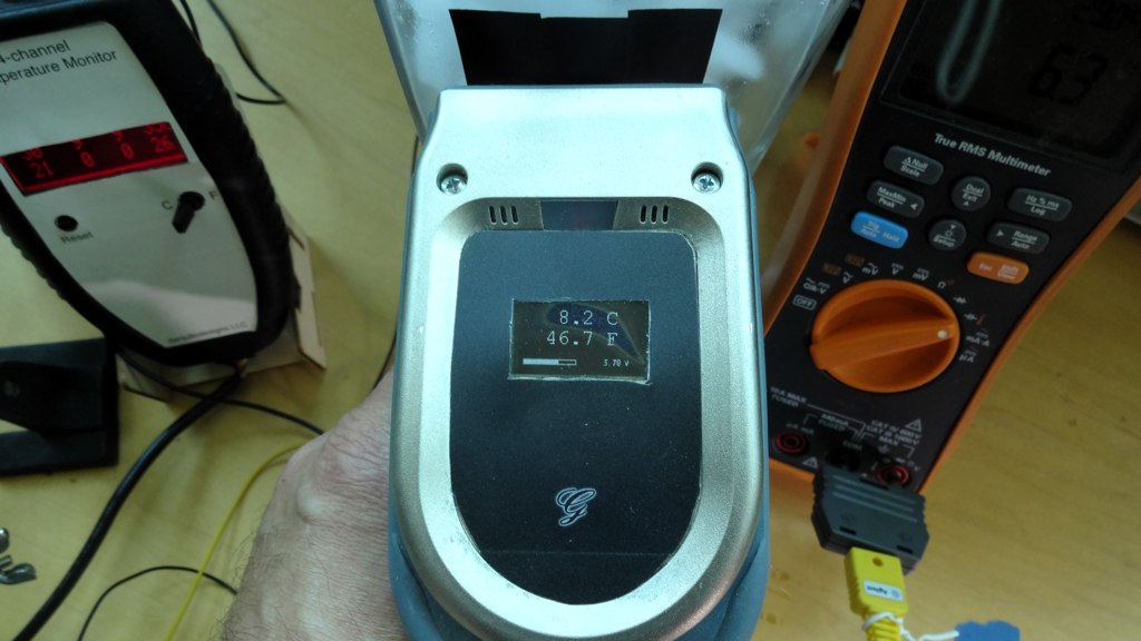
Wanting to see how accurate my lepton is, I hacked lep_test6 into lep_test9 (in the github repository) adding the ability to change the emissivity in the RAD Flux Linear parameters setting as well as compare the output of the spot meter function (that can average a specified set of pixels in a specified location in the image) with output pixel data. The spot meter can be used to get temperature when AGC is enabled and the pixel data does not contain actual temperature values.![]()
I then attempted to compare the temperature output from the Lepton with other temperature measuring devices for a variety of materials and object temperatures (being a hot summer day, I didn't get much opportunity to play with the ambient temperature). I would call this very amateur science...Short summary: I found the device fairly accurate without having to change the default emissivity setting (with one exception) and the spot meter works as advertised. Emissivity investigation will have to wait for another day.
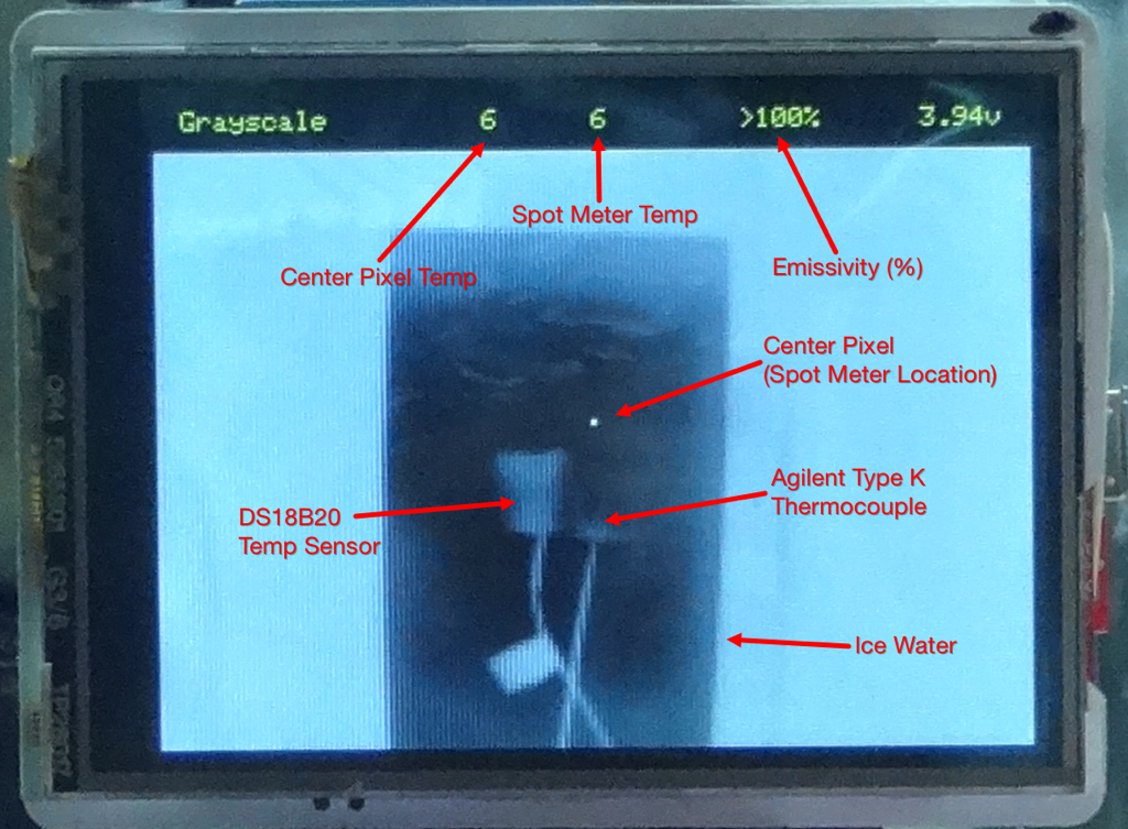
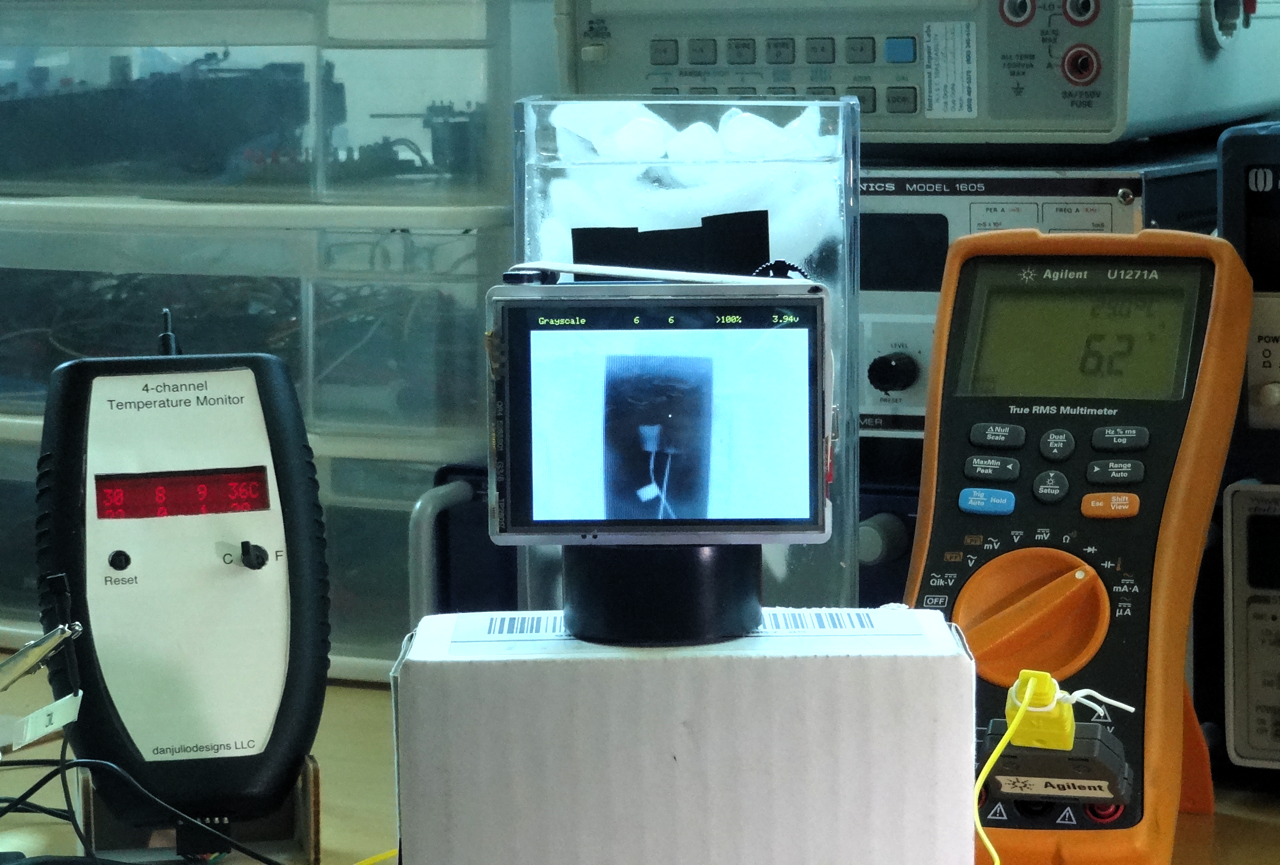
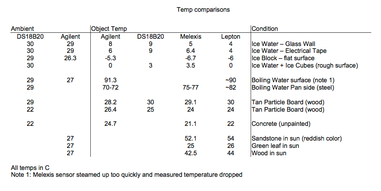
Longer Description + some dataThe test setup included a 4-channel Dallas DS18B20 temperature probe I made years ago, an Agilent multimeter with a type K thermocouple and a home-made IR Thermometer based on the Melexis MLX90614 sensor. I attempted to use either one DS18B20 or the Agilent probe to capture the ambient temperature and then as many sensors as possible to also read the object temperature. Basic claimed accuracy (over the temperature ranges I used) of the DS18B20 sensors is +/- 0.5°C, for the Agilent sensor, 1% + 1°C and for the Melexis sensor, 0.5°C.
![]()
I held the Melexis sensor very close to the object since it has a very wide field of view and averages all the thermal energy in its scene. Here it is measuring the temperature of a "blackbody" (electrical tape) on the side of a vase of ice water.
![]()
Measuring temperature is hard... There is the basic accuracy of the sensor itself and then how it interacts with the environment. I saw a quite bit of variability for all sensors, especially the IR sensors. The DS18B20 sensors tracked each other very well. However I think that the lead temperature makes a big difference so when their plastic cases were touching an object, the temperatures recorded may have been wrong because the leads were at a slightly different temperature. The thermocouple varied based how it touched the object (although it has very fast settling time).
![]()
As can be seen from the data, the Lepton generally agreed with the other sensors. I expected worse performance, partly because of the device specs and partly because I expected the surface emissivity to play a bigger role.
Not included in the above table (a late add) was a measurement of a soldering iron set to 350°C. The Lepton read 181°C and it wasn't until the emissivity setting was lowered to 35% that the temp was close (353°C). I'm not sure why and would love to hear any thoughts...
-
Lepton AGC
07/18/2018 at 03:23 • 0 commentsMost demo code, including my lepton_test6 sketch, use a simple linear transformation from the raw 14-bit count or 16-bit radiometric temperature data to 8-bit values that are then transformed to RGB values via a lookup table (colormap). To do this the maximum delta between all pixels in the frame is computed and then each pixel value scaled as follows:
8-bit pixel value = (Pixel value - minimum pixel value) * 255 / maximum delta
However this simple algorithm fails with scenes that contain both hot and cold regions because it tends to map most pixel values to either the maximum or minimum values resulting in images with little contrast between the two temperature extremes.
The Leptons have an AGC (Automatic Gain Control) function that can be switched on to try to ameliorate the shortcomings of a simple linear transformation for temperature data to be displayed. FLIR has an entire - slightly confusing - section (3.6) in the engineering data sheet describing their AGC implementation - actually two different forms of AGC they call histogram equalization (HEQ) and linear histogram stretch. They claim improvements over traditional histogram techniques with their HEQ algorithm and include many parameters to tune the algorithm but don't deeply describe it. They don't describe their linear histogram stretch algorithm.
Enabling AGC mode (and disabling radiometric calculations - something that took me a few weeks to figure out) generates 8-bit data out of the selected AGC algorithm. There are many parameters but they claim default values should produce good results. There is an additional, somewhat mysterious, AGC Calculation State Enable as well. The description states "This parameter controls the camera AGC calculations operations. If enabled, the current video histogram and AGC policy will be calculated for each input frame. If disabled, then no AGC calculations are performed and the current state of the ITT is preserved. For smooth AGC on /off operation, it is recommended to have this enabled. "
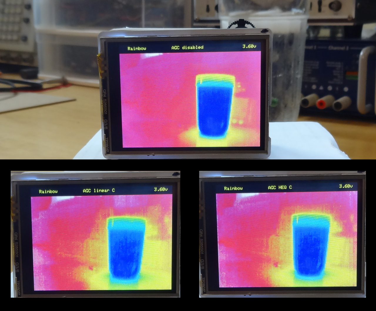
Since reading the AGC section I have been interested in how well their implementation performs. I wrote a sketch, lepton_test8, that allows cycling between the original linear transformation and 4 variations of FLIR's AGC function. They are- "AGC disabled" - Radiometric mode enabled, my code linearly transforms 16-bit data to 8-bit data.
- "AGC linear C" - AGC mode enabled, linear histogram stretch mode, AGC Calculation State enabled. Lepton outputs 8-bit data.
- "AGC HEQ C" - AGC mode enabled, histogram equalization (HEQ) mode, AGC Calculation State enabled. Lepton outputs 8-bit data.
- "AGC linear" - AGC mode enabled, linear histogram stretch mode, AGC Calculation State disabled. Lepton outputs 8-bit data.
- "AGC HEQ" - AGC mode enabled, histogram equalization (HEQ) mode, AGC Calculation State disabled. Lepton outputs 8-bit data.
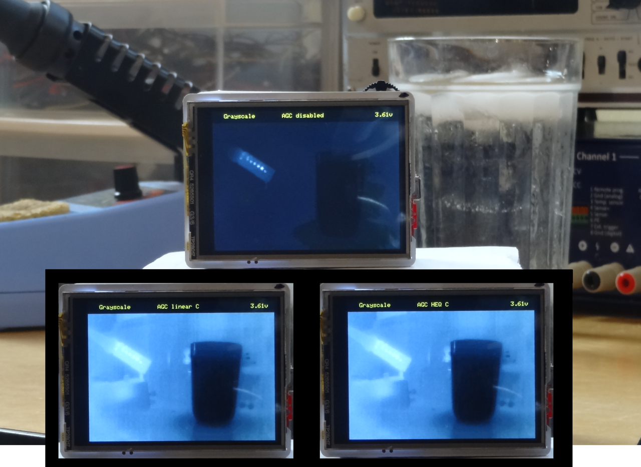
I then compared a scene with hot and cold components (soldering iron and ice-water with a room-temperature background) using the various modes and various color maps. I also did some informal testing with less dynamic scenes. The TL,DR summary is that the AGC modes generate distinctly better images in scenes with large dynamic range. They do only slightly better with more mono-temperature scenes. I couldn't see much difference between the linear histogram stretch and HEQ modes. I also couldn't see much difference with the AGC Calculation state enabled or disabled (perhaps I saw artifacts left behind when the camera panned).
Following are some pictures showing output with different modes. You can see the soldering iron and glass in the first image. The mode and current colormap is shown at the top of the camera's LCD display.![]()
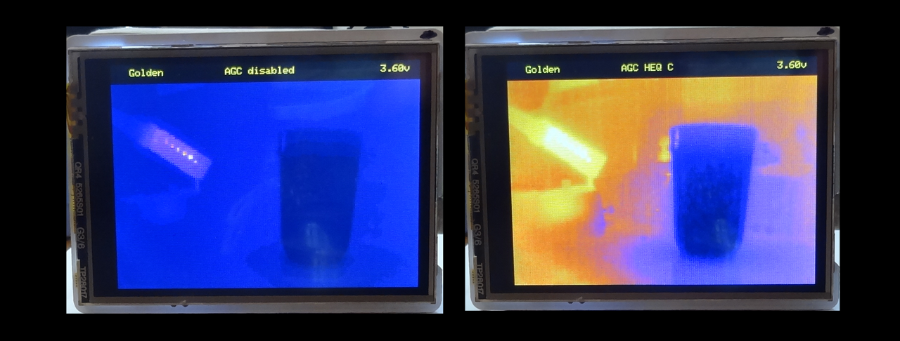
A big difference with the "Iron Black" and "Golden" colormaps.
![]()
![]()
The advantages of the built-in AGC modes was less pronounced when the temperature range of the scene was less. The soldering iron was removed for the first two sets of pictures. It was replaced and the glass removed for the last set of images (however you can still see the cold spot on the desk where the glass sat).![]()
![]()
Solder iron only.![]()
Disadvantage of built-in AGCFLIR touts the benefits of their algorithm for the display of temperature data. My testing bore that out. However because the AGC algorithms remove temperature data and scale the image to the full 8-bit range, they cannot be used if you want to display the current temperature scene inside of a larger temperature range.
One annoying artifact of scaling the Lepton's output to the full color map range is that the image will completely change when something with a higher- or lower-temperature is brought into the scene. It can be handy to scale the data to a larger range so the image doesn't change so dramatically as you pan across scenes with different temperature components. For example, assuming you were looking at the heat leakage of your house on a cool winter day, you might scale the data to a 0-40C range. Then the image won't change radically as you pan across various hot and cold parts of the house.
Ideally, with enough processing power, one could take the 16-bit temperature data and run that through a software AGC algorithm that matches the performance of FLIR's algorithm but lets the user select the displayed temperature range. Unfortunately that's beyond me at the moment. -
VoSPI
07/13/2018 at 04:05 • 2 commentsLepton's use an output-only slave SPI interface called VoSPI (Video SPI) to output pixel data with a maximum 20 MHz clock. It has the feeling of something that has evolved over time as FLIR added newer models. It definitely does not feel like something that would be designed from scratch. The Lepton's basic unit of data transfer is a 164- or 244-byte packet. The 164 byte packets contain 80 16-bit pixels (of which 8-, 14- or 16-bits of data may be valid for the Lepton 3.5 depending on its operating mode). The first 4 bytes are a 16-bit ID word and a 16-bit CRC word (that I have not, to-date, attempted to use). The 244-byte packets contain 80 24-bit (8-bit each for R, G and B) pixels and the ID and CRC words. The ID word carries a line number (0-59 or 0-62).
The 80x60 pixel Leptons (2 and 2.5) output 60 packets per frame (or 63 packets if telemetry data is also included with the pixel data). This turns out to be about 2 Mbits/second for a 100% dedicated interface.
The 160x120 pixel Leptons (3 and 3.5) modify the protocol a bit in order to carry 4x the data. They add a segment number to the ID word of packet 20. Segment numbers 1-4 indicate that the entire set of packets contain a valid segment. It definitely would have been easier (less buffering and easier processing) if the segment number was in the first packet. This family of device requires a minimum of 8+ Mbits/second although I found that with the Teensy I had to use 16- or 20-MHz SPI clocks. I noticed most of the other demo programs also use much higher SPI clock rates.
All Lepton's have a hard requirement that the host must get the data out within three lines of when it is generated in the Lepton or it will lose synchronization and be unable to output valid data. All Leptons also output what are called "Discard packets" that are indicated by a specific bit-pattern in the ID Word. The host is to ignore these packets but keep reading for good data later.
In my testing I also found that until synchronized they may output nonsensical non-discard packets too.
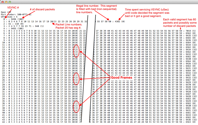
I wrote a quick Teensy sketch that enabled VSYNC and polled it until asserted. It then read packets until it saw a complete segment, or it saw invalid data (invalid line number) or a timeout was exceeded (maximum VSYNC period). The program could usually sync with the Lepton within a handful of VSYNC periods. The output from a typical run is shown below. Once synced you can see a new valid frame every twelve frames (or 1/3 the data frame rate). These are the frames that get displayed. Each line number (0-59) represents 160 bytes of pixel data.![]()
It is interesting to see that alternating segments have discard packets. I don't have an explanation for this although I wonder if this has to do with the timing of my SPI bus (16 MHz) and the Lepton's internal processing rate.
Getting this code running meant I could get valid data out of the device.
The core of the code:void loop() { bool curVsync; curVsync = (digitalRead(pin_lepton_vsync) == HIGH); if (curVsync != prevVsync) { Serial.printf("%3d : ", counter); ProcessSegment(); Serial.println(); counter++; } prevVsync = curVsync; if (counter == 106) { WaitForChar(); counter = 0; } } void WaitForChar() { while (!Serial.available()) {}; while (Serial.available()) { (void) Serial.read(); } } void ProcessSegment() { uint32_t startUsec; bool done = false; line0count = 0; discardCount = 0; startUsec = micros(); while (!done) { if (ProcessPacket()) { done = true; } else if (AbsDiff32u(startUsec, micros()) > LEP_MAX_FRAME_DELAY_USEC) { done = true; } } Serial.printf(": %d (%d)", AbsDiff32u(startUsec, micros()), discardCount); } bool ProcessPacket() { uint8_t line = 0; uint8_t seg; bool done = false; SPI.beginTransaction(SPISettings(16000000, MSBFIRST, SPI_MODE1)); //Start transfer - CS LOW digitalWrite(pin_lepton_cs, LOW); SPI.transfer(frame, 164); //Repeat as long as the frame is not valid, equals sync if ((frame[0] & 0x0F) == 0x0F) { discardCount++; } else { line = frame[1]; if (line == 0) { line0count++; } //Get segment when possible if (line0count > 1) { done = true; } else if (line >= 59) { Serial.printf("%d ", line); done = true; } else if (line == 20) { seg = (frame[0] >> 4); Serial.printf("%d(%d) ", line, seg); } else { Serial.printf("%d ", line); } } //End transfer - CS HIGH digitalWriteFast(pin_lepton_cs, HIGH); //End SPI Transaction SPI.endTransaction(); return(done); } -
Teensy Test Code
07/12/2018 at 04:23 • 0 commentsInitially I connected the Lepton to a Raspberry Pi 3 and ran demos from the Group Gets repository. However many of those are written for the lower-resolution Lepton 2 family of modules. I hacked a couple of them with less-than-stellar results because of the much larger dataflow from the Lepton 3. I had more luck with Damien Walsh's leptonic but even it would occasionally lose sync on a lightly loaded Pi. This lead my decision to try to use the VSYNC output to make it easier to synchronize the VoSPI transfers to the Lepton's video engine.
FLIR has a reasonable set of default settings. For example the Lepton 3.5 is ready to output radiometric data (with absolute temperature values for each pixel) immediately after booting. However changing any of the default settings (e.g. enabling VSYNC) requires using the I2C interface to access its command interface (IDD). They provide a C++ library that is designed to compile on 32- or 64-bit Linux machines that I ended up porting to the Teensy Arduino environment. With this I was able to enable VSYNC and with the Teensy and Lepton on a proto board start to figure out how to reliably get video data out of it. It's a bit picky about the timing and data gets garbled if the host isn't able to keep up.
The Lepton 3 and 3.5 output data in 4 segments, each one quarter of a complete frame. The segment length may vary depending if the data is formatted as temperature or AGC-processed data or is 24-bit RGB colorized values or includes additional telemetry information. Each segment is comprised of a set of 60 (or more) 164-byte or 244-byte packets, including packets specifically designed to be discarded while the Lepton prepares the valid data and any optional telemetry data. Although the Lepton's internal frame rate is about 26.3 Hz because of government regulations it only outputs ~8.8 frames of video per second. However it generates data for all frames leading to a VSYNC rate of ~105.3 Hz (4 segments/frame). This means the host has to read, and process for validity, an entire segment after each VSYNC. It took me a while before I could manage this on the Teensy.
The host must resynchronize with the Lepton whenever it gets out of sync or it will receive only garbage data. This requires idling the VoSPI interface for at least 186 mSec. I found that it takes the Lepton a few VSYNC pulses to start outputting valid data. When the host is in sync then it will output 4 consecutive good segments on 4 consecutive VSYNC pulses every 12 VSYNC pulses. The other eight VSYNC pulses contain invalid segments (identified with a segment number of 0). Because my test fixture uses a single SPI interface to read data from the Lepton and then write frame buffer data to the LCD display the test sketches are only able to reach about half of the maximum frame rate (~4.4 frames/sec).
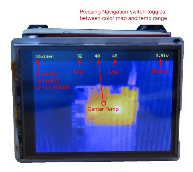
I put the ported IDD library and three test sketches into a github repository. The sketches also use the Adafruit ILI9341 and GFX libraries for the LCD module (although the code has its own routines to write pixel data to the display).lep_test6 - This sketch takes the default 16-bit absolute temperature (Kelvin * 100) value of each pixel and linearly scales the data to 8-bit values that can be run through a color map look-up table for display. Because the data has absolute temperature values it is easy to display the temperature (currently without worrying about any real-world emissivity issues) of the center of the image. Normally the scaling maps the data from the minimum and maximum in the frame. However this sketch allows the user to select a few temperature ranges to scale the data in so the image does not change radically as different temperatures enter or exit the frame.
![]()
The Lepton also has a more sophisticated AGC capability that is claimed to produce better images than linear scaling. I spent a lot of time trying to figure out how to enable this function (ultimately I found I had to disable the radiometric calculations before the it would output AGC processed 8-bit values). I am still comparing the image quality but I wrote two additional sketches with AGC enabled.
lep_test5 - Enables AGC and takes the 8-bit output through color maps in the code for display.
lep_test7 - Enables AGC and 24-bit RGB output. The Lepton generates RGB data from one of its built-in color maps and this is read and converted to 16-bit RGB for the LCD display. Mainly I wanted to see if I could handle the additional data.
Future plans include attempting to interleave writing data to the LCD with reading it from the Lepton to improve the frame rate. I'd also like to see if I can include an emissivity calculation to make the temperature data more accurate depending on the surface. I think I'll enable AGC and then use the I2C command interface to get absolute temperature data at the selected location in the image. -
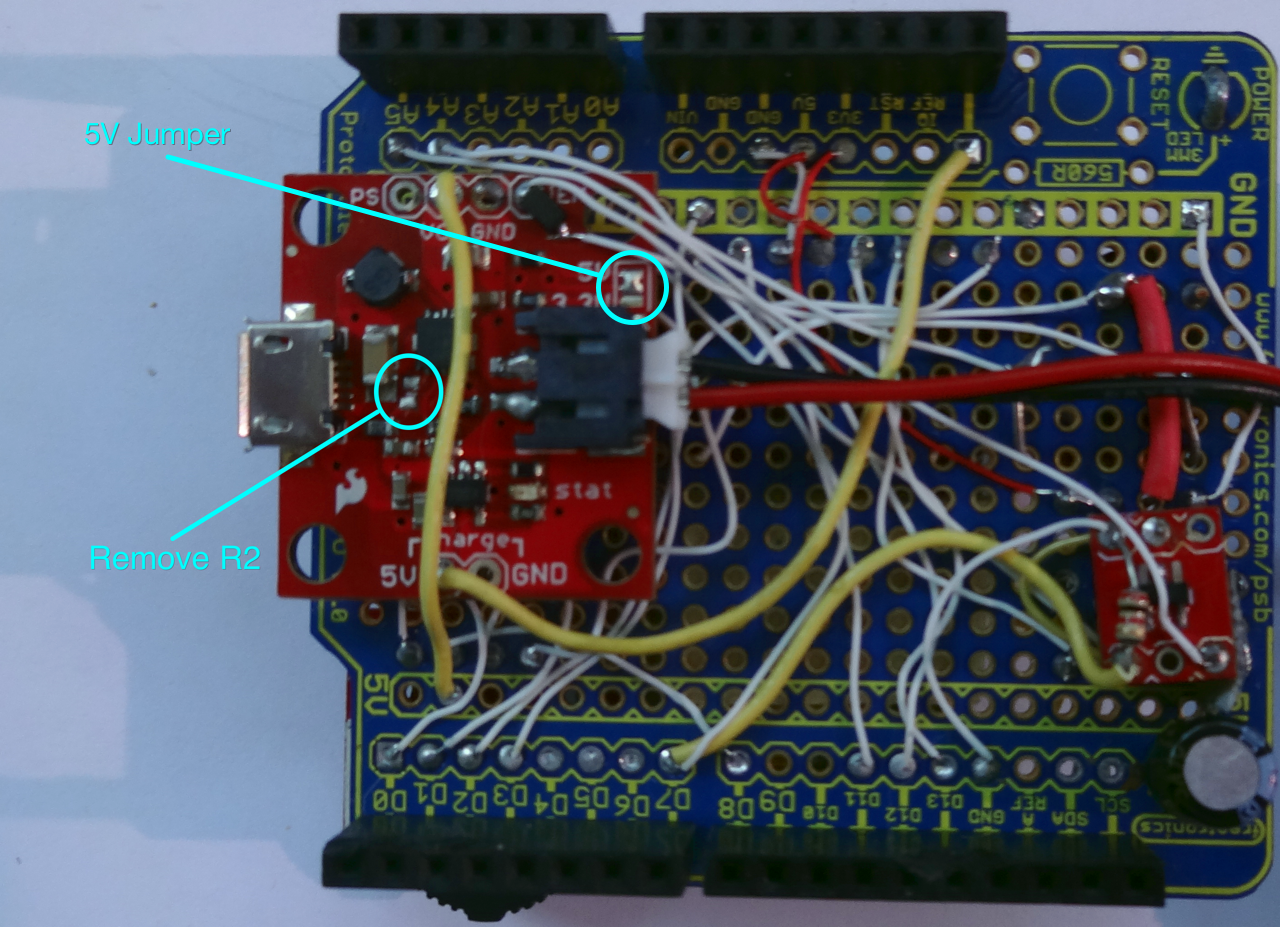
Mods to PowerCell
07/10/2018 at 19:17 • 0 commentsForgot to add this image to the hardware description. Its a close-up of the front board showing the mods made to the Sparkfun PowerCell board.
![]()
-
Test platform hardware
07/10/2018 at 19:08 • 0 commentsIntroduction
The test platform hardware is pretty straightforward. I used an Arduino shield style breakout board to make it easy to connect the Teensy to the display and imaging module. Most connections between the Lepton module, LCD and Teensy are direct and documented in the image and included PDF schematic using the Arduino-style signal notation. The additional circuitry is for power management and control buttons. A LiPo charger/boost converter supplies 5V power to the various boards (the Teensy 3.3 volt regulator drives the 3.3v rail). It's controlled using a soft-power switch. The button initially enables power and then the Teensy drives D7 to hold power. D7 is released to shut power off. A few modifications are made to various boards.
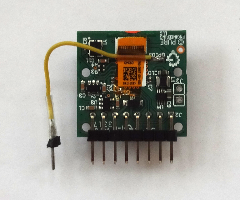
Lepton Breakout ModificationPure Engineering provides a SMT pad on the back of their breakout for the Lepton's GPIO3 pin. This pin may be used to output a 105.3 Hz VSYNC signal that indicates the start of a segment transmission (a segment is 1/4 of a full frame of data and requires at least 60 164- or 244-byte SPI transfers). It is useful for synchronization. I use it as an interrupt on the Teensy to trigger a set of transfers. I brought the signal out to a pin plugged into the same header that the rest of the breakout board's pins connected to. I also removed the 2-pin power input (J3) that pokes out of the back of the breakout. A pair of 4.7 kohm pull-up resistors pulled to 3V3 is connected to the I2C signals.
![]()
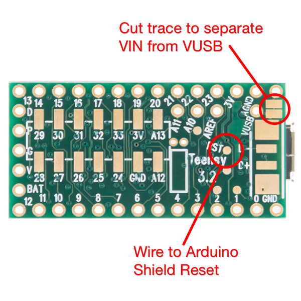
Teensy 3.2 ModificationsI cut the trace between VIN and VUSB on the back of the Teensy. I use VUSB as the input power to the charger and let the charger supply 5V that is fed back to the Teensy via its VIN to power it. That way the board may be charged via either the Teensy USB connector or the charger USB connector. The VUSB power line was connected to the spare Arduino expansion pin and routed to the front board containing the charger via the header. I also added a wire connected to the Teensy Reset pad on the bottom of the board and routed to the Arduino RST header pin. This allows the Reset button on the LCD shield to reset the Teensy.
![]()
Power Circuitry
The power circuitry is built around a now-obsolete Sparkfun PowerCell board. However I think one of their newer charger/boost converter boards (or something similar from another supplier) will work. The main requirements are an active-high boost converter enable signal and very low quiescent current when the boost converter is disabled (so-as not to discharge the battery). The system takes less than 250 mA at 5V. I removed the 10 kohm pullup R2 from the Sparkfun board to reduce quiescent current. The enable is held low by the resistor divider until the button is pressed enabling power. As soon as the Teensy starts executing code it drives D7 high which holds the enable high (the user has to hold the power button until D7 is high which is a few hundred mSec and indicated by the LCD clear screen). The resistor divider driving A6 is used to sense whether or not the button is being pressed. It does this by seeing the higher voltage when the button is pressed. The BAT54 diode is used to isolate the Teensy from Vbatt when the button is pressed. Different diodes may be used but they should be low Vf schottky units (the diode I used has about 0.3v Vf).
The battery voltage is sensed using another resistor divider feeding A7. To reduce power consumption when the system is off a n-channel MOSFET is used as a switch and to keep current from flowing into A7 when the system is off. Most of the n-channel MOSFET parameters are unimportant and a variety of devices may be used. The most important parameter is Vgs since the control signals are 3.3v based. Rds-on should also be fairly low, although with the resistors it may be even a few ohms if that's all you have in your parts drawer. A small - and non-critical - resistor holds the gate input low when power is removed.
Rocker/Navigation ButtonThe 3-way navigation button I used is also now obsolete. It can be moved right or left or depressed. My use is to scroll through items with the left/right movement and select between menus with the press. Any three individual or grouped buttons may be used. The firmware enables internal pull-ups in the Teensy.
Note about resistor valuesThe resistors used in the two voltage dividers where just units I had laying around. I was shooting for a 3R to R ratio so the voltage inputs on A6 and A7 would always be less than the Teensy's internal reference voltage of 1.2 volts. You can use a different combination as long as the voltage on A6 and A7 is less than 1.2 volts for a fully charged battery (~4.2 volts) and the series impedance is in the low 10k ohm range. A constant in the firmware represents the ratio and can be changed to match the selected resistors.
Note about wiring details
About the only critical wiring is the SPI lines. The firmware uses SPI clock rates up to 20 MHz so the wiring for these signals should be as short as possible.
Lepton 3.5 Thermal Imaging Camera
Documenting my experiments with the FLIR Lepton 3.5 thermal imaging camera.