Joe Miller
-
SOLoRa Power Management Circuit Description
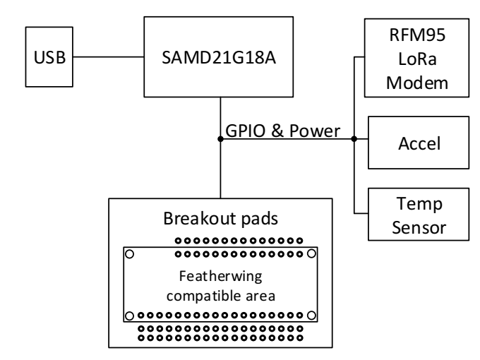
07/30/2018 at 01:05 • 0 commentsThe SOLoRa board was borne out of the desire to make a hassle-free, set it and forget it design, that could be affordable, expandable and buildable by most hobbyist. I hope I have achieved these goals with this design while having to make tradeoffs to balance these features. I began with wanting to use the low-power features and Arduino Zero compatibility of the SAMD20 microcontroller. For expandability and flexibility, I included breakout pads for Adafruit Featherwing headers. Whether they be used to attach Featherwing boards or for general purpose prototype mezzanine boards is up to the needs of any project. I chose the RFM95 LoRa Transceiver board because of the ease to soldering, cost and compatibility with the existing and proven LMIC LoRaWAN library. The low-cost temperature and accelerometer devices were added to fill left over board space for test and demonstration purposes.
![]()
SOLoRa Flexible Power options
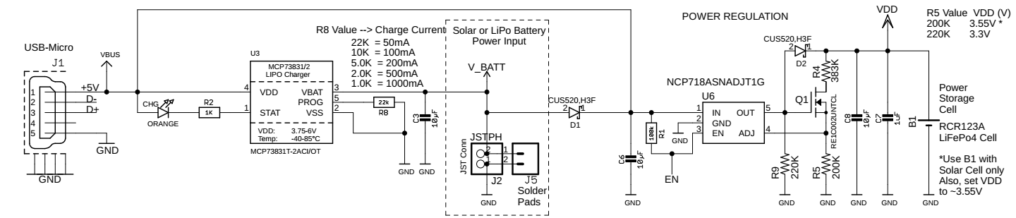
Solar powering this node was the main power source of choice for this board, but I saw some cases where other power sources would be more appropriate so when I designed the power section I attempted to make it configurable. The board can be powered by USB, which is good for development or permanent indoor applications. It can also be powered by a LiPo and even includes a LiPo battery charger IC. An external battery or other unregulated power source is also possible with this design. Two key design elements make the always-on solar power practical are the low reverse leakage regulator and the reservoir battery (or power storage cell).
![]()
The complete power management circuit of the board is shown in the schematic below (see the files area for the complete SOLoRa schematic). The Solar versus LiPo or external power option are enabled by selectively installing the components that support that option. USB power option will always work and will override the other two power options while it is plugged in.
![]()
Storage Cell
Notice that the storage cell is connected directly to VDD at the end of the power management circuit. This is key. I used a LiFePO4 cell here because it reaches full charge at 3.6V. This voltage is also the typical maximum guaranteed operating voltage of most electronic devices and components. This means that an additional regulator between the storage cell and the main circuitry is not required. On the SOLoRa board, I set the regulator to 3.55V to add a bit of margin.
![]()
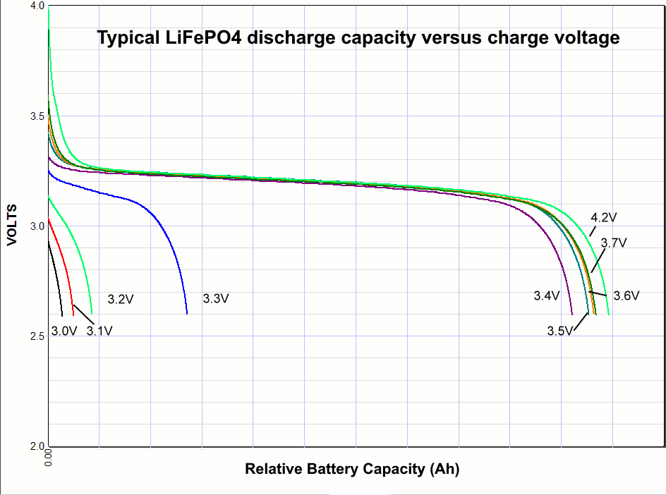
The LiFePO4 battery capacity is also less sensitive to charge voltage if the charge voltage is 3.4V or above, see diagram above. In addition, The LiFePO4 is also less sensitive to overcharging and does not exhibit the thermal runaway issues like LiPo and Li-ion batteries. The SOLoRa power management circuit acts as a “float” charger. The charge current is limited by the solar cell maximum output current.
The Regulator Design
Employing a super-efficient energy harvesting circuit is a very good idea. I, however, went with a linear regulator with modifications because the advantages of this circuit really added up. Basically, a linear regulator is very inefficient compared to a switching regulator. I have used the TPS62740 switching regulator on many of my professional designs. It is an excellent regulator. It’s efficiency, especially at low current, is very hard to beat. Two things against it, this project, is that It costs more and is not easy for the typical hobbyist/maker to solder. The BQ25505 energy harvesting IC is another very good part when you are trying to squeeze every Coulomb of current out of a power source and deliver it to your circuit. However, it too is hard to solder, cost more than $5 USD and still requires more support components including a regulator on its output.
What about the terrible waist of energy a linear regulator brings to a low-power design such as this?
The Fact that I can still make my current budget with my preferred solar cell is the main reason I can use a low cost and easy to use linear regulator. I tested my prototype circuit using a 53x30mm 5V solar panel. It’s small, smaller than my board. The kicker is that I only paid $0.60 USD. If I need twice the current I could pay $1.20USD for a panel twice the size and still be lower overall cost than an energy harvesting circuit with an MPPT front end.
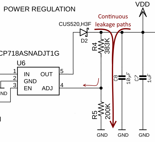
Low-Leakage Regulator Design
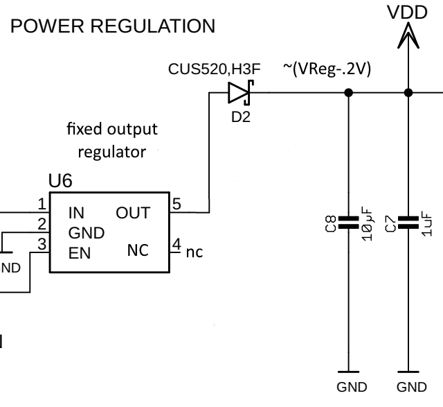
Below is a closeup of the regulator section of the power circuit. The components on the output of the regulator prevent leakage when the power source is not present (like night time). These components prevent the charge in the Power Storage Cell (B1) from leaking back and through U6 to ground.
![]()
If you really wanted to simplify the circuit and save costs you could insert a fixed regulator at U6. There would be no need for the feedback resistors or the FET. If you intend to power your board with continuous source, like the USB input, a LiPo or other external power source you wouldn’t even need the diode. You could short that out and simply use a 3.3V fixed regulator. If your intent is to use solar power, adding a diode will prevent leakage back through the output terminal of the regulator to ground when the solar panel stops providing power for the day.
![]()
To compensate for the diode voltage drop, a fixed regulator with an output voltage of 3.6V might do the trick. This would provide approximately 3.4V to the Storage cell. The possible issue you could experience is that the voltage drop of the diode is temperature and current dependent. Under these circumstances VDD could be anywhere in the 3.3 to 3.5V range. At 3.3V, you would not realize the full charge capability of the LiFePO4 cell. See the charge voltage versus capacity graph above. If on the other hand you chose to go with a fixed regulator output voltage of 3.8V you run the possibility of exceeding the guaranteed operating voltage of components in the main circuit.
Using an adjustable regulator with feedback resistors connected after the diode drop would guarantee tight regulation at VDD. This however, would introduce leakage currents that would bleed the storage cell. The leakage would be approximately 6uA. The addition of the FET would shut-off this leakage path when voltage at the output of the regulator is not present.
![]()
With the FET in the circuit, the leakage, at night, is less than 1uA. I did measure the 6uA leakage under dusk and dawn conditions, but this condition is temporary.
In hind sight, after creating a more thorough current budget, the leakage current of 6-7uA due to the feedback resistors may not a be all that big of an issue. The out of the box Arduino M0 sleep method to put the M0 to sleep is presently 500uA! I have heard that this can be reduced to around 40uA by switching all unused pins to analog inputs. One could argue that because I am meeting the current budget, for my basic use-case with a fair margin, the additional 6uA burden added by not including the FET is insignificant.
-
Current Budget Tool
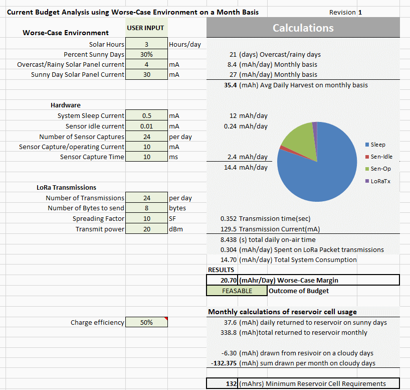
07/24/2018 at 19:24 • 0 commentsFirst (full) power budget spreadsheet completed and added this project. This spreadsheet, tailored to the SOLoRa board, is a vital design tool to properly analyze all aspects of a system design for always-on IoT node with intermittent power harvesting input. In my initial feasibility study I performed notebook calculations with a mix of early empirical data and best estimates. This spreadsheet's calculations, and the data contained within, more accurately models the actual circuit performance. The microcontroller's sleep current is much higher than I like so I will continue working on reduce it. Even with the 500uA sleep current, as shown, my power budge is feasible. The input parameters of the budget worksheet shown below uses conservative settings for Spreading factor (10), with 7 being the lowest power consumption. The output power is also set to 20dBm, the maximum. After site testing, one could lower these values to increase budget margins.
![]()
-
Power Primer
07/15/2018 at 07:26 • 0 commentsThe challenges of always-on power with intermittent energy harvesting
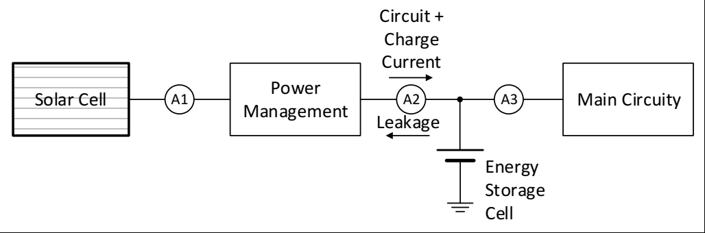
When energy from the main power source is available, current (A1) feeds the energy storage cell and the main circuit with power. Ideally, while power is being generated, it is desirable for A1 = A2, which means there is no power loss through the power management circuit. Also, when the power source is not available and the power storage cell supplies power to the main circuit (path A3) it is ideal that none of the main storage cell's energy is lost due to reverse leakage back to the power management circuit (-A2).
In the end, the average current over time (Ah) provided by the power source (A1) must be greater than the time-use percentage of power consumed by the the Main Circuit (A3) plus the time-use percentage of reverse leakage back to the regulator when power is not available at the main source plus any A1-A2 loss (Power management leakage).
![]()
Power Management Design Trade-offs
These trade-offs directly affect the always-on design margins when used with intermittent power sources.
Component Factors that improve design margins Tradeoffs Solar Cell Larger or more efficient panel Cost Power Management Efficiency
Integrated vs discrete solutionCost
Cost, size, timeMain Circuit (software) Lower Duty Cycles Lower data rates Main Circuit (microcontroller) Lower core Voltage
Peripheral management, sleep modesLower process speed
Complexity (dev time)Main Circuit (Sensors) Lower power, faster integration period Price, quality Storage Cell Size is dependent on multiple factors
given abovedependent on other
design parametersAnother factor that affects always-on power margins are the site dependent equivalent solar hours per day. This site dependent variable is used in calculation as a weighting factor for the above design trade-offs.
Of course all these factors are to consider the overall design priorities and specifications. For instance a priority on my design includes easy to assemble, low cost and flexibility. This has shaped my design, most considerably in the Power Management circuit. I could not find an off-the shelf solution that satisfied these three goals so I design my own solution, a hybrid of an adjustable linear regulator with a shutoff circuit to prevent leakage back into the regulator. The idea of using a linear regulator is not the first topology one would think to use in a circuit with high efficiency ambitions, but the number work out. I will show my calculation and justifications in an upcoming log.
-
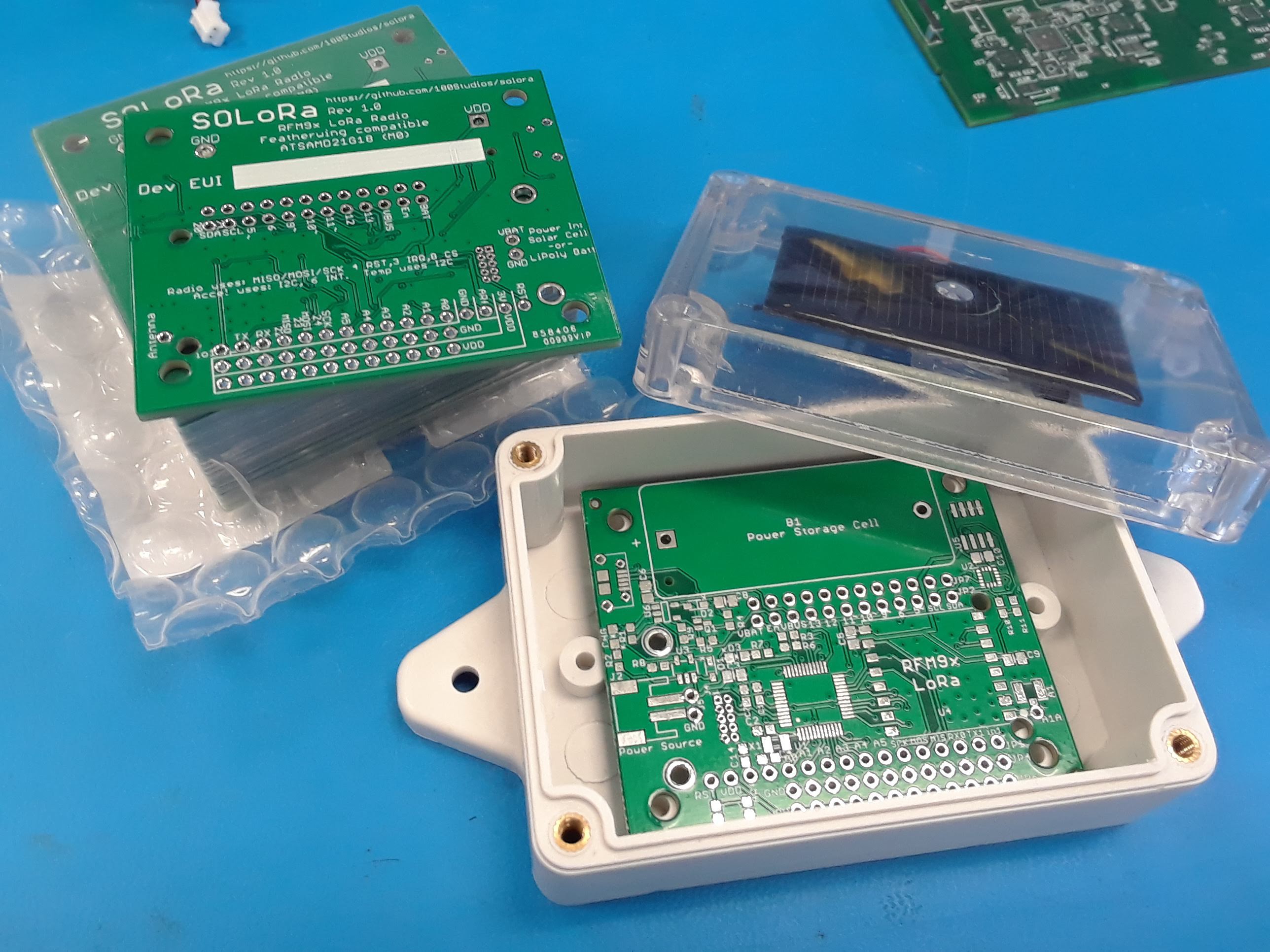
Received PCBs Today
07/12/2018 at 19:10 • 0 commentsThis is the GIT repo for the PCB design:
https://github.com/180Studios/SoLoRa.git
![]()
Alternatively, I put my design up on the Seeed Studio Fusion Gallery, so you can order them directly from them. Search for SoLoRa . Cost is ~$1/board with shipping.
Note: These just arrived so I have not yet tested them.
-
Power Train Prototype and measurements
07/11/2018 at 21:30 • 0 commentsThis is the prototype of the power train for the project. I used this to measure its characteristics.

In full sun I measured 90mA of charge current into my LiFePo4 battery when perpedicular to the Sun and 60mA. 30mA on a cloudy day and 23mA when tilted at 45-degrees to the apparent Sun direction. 500uA in shade, not pointing at the sky. 20mA of charge current was measured through a window in my house pointing at a blue sky (the Sun not in view).
The back-leakage from the battery storage cell to the circuit with no sun was ~1uA, ~6uA at dusk and dawn conditions.
SoLoRa - Solar Powered always-on IoT sensor node
Unique, compact power conditioning enables always-on sensor monitoring and Long-Range radio (LoRaWAN) link for IoT applications.