Jan Waclawek
-
100uF ceramics, first impressions
08/02/2018 at 22:33 • 0 commentsI've got some ceramic 100uF capacitors (1210 100uF X5R 6,3V 20% CL32A107MQVNNNE by Samsung). They came from a local supplier quite a bit cheaper than they sell at the major outlets like Mouser - this is a low-selling item at the local supplier and apparently had not been hit by the current ceramic-craze, yet...
Using one of them instead of the 3x10uF on the L476-DISCO's RTC yielded almost 10 minutes of RTC run. This again is better than what the charge equation would indicate (100uF * (3V - 1.7V) / 300nA is cca 7 minutes), but it roughly follows the expectations.
When the voltage drops below some 1.7V where the 32kHz oscillator stops working, the RTC's consumption significantly drops, so it retains the "stopped time" for tens of minutes - and when power is restored, it continues where it left off - that's why it's easy to know the "maximum endurance".
Of course this is still not what we want - even if the leakage is much lower than indicated (DS says 100 MOhm*uF with the usual method of "Rated Voltage, 60~120 sec." - which is orders of magnitude off the real, non-DA-confused leakage), it's still impractical to pack more than a dozen of them, and that buys no more than two hours of running the 'L476 clock. Clearly, a lower-consumption RTC is needed - waiting for the mentioned low-consumption module to arrive.
And the dielectric absorption thing is HUGE... measurement running, stay tuned!
-
ToDos
07/16/2018 at 00:33 • 0 comments- Buy 100uF X5R 4V capacitors. There are larger capacitances around, but it's not necessarily good to push things to the edge - larger capacitors in the same package means thinner dielectrics which may mean higher leakage. Try several manufacturers, maybe also different dielectrics.
- Measure their leakage (and dielectric absorption) - after hours of charging.
- Buy the 60nA RTC module.
- Connect it with the L4-DISCO, write software to control it, connect the capacitors and charging arrangement.
- Test, powerred from the onboard 3V regulator.
- If success, use the solar cell as primary source, and build a simple step-up controlled from the 'L476.
- If time and money permits, experiment with low-input-voltage stepup circuits for the primary power.
-
First clock
07/16/2018 at 00:23 • 0 commentsAfter finding out that the project could be accomplished in a "humanly" simple way, unfortunately, there was not enough time left to acquire the parts - a bunch of 100uF+ ceramic capacitors and a ultralow-consumption RTC. (Btw., turns out, theadvertised 40nA RTC module is not yet available from the "usual outlets", but another module consuming only 60nA is, at a reasonable price, and it even features a calibrated-RC-mode when the consumption drops to mere 17nA!) So, using a couple of 10uF 0805 ceramic capacitors at hand, and the built-in RTC of STM32L476 on the L4-DISCO board, I proceeded at least with a basic proof-of-concept project.
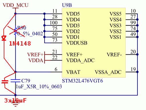
The VBAT pin, supplying the built-in RTC in mcu, on the DISCO board is not brought out separately but is connected to VDD - luckily through a resistor, R90. This has to be replaced by a 1N4148 diode, and the 10uF capacitors have to be added in parallel to the existing 1uF C79:
![]()
1N4148 has a leakage of a few nA at 3V reverse voltage. While charging (i.e. mcu is supplied through VDD), mcu supplies the RTC internally, thus no current flows through VBAT, so - after several hours of sunlight/charging even the dielectric-absorption-capacitance of the storage capacitor is fully charged, so only leakage flows through the diode, which we hope will be only a few nA. At that current, the forward voltage drops towards tens of mV, which is something we probably may sacrifice - it's not worth to experiment with exotic low-leakage transistors, or even relays, in place of a simple diode.
![]()
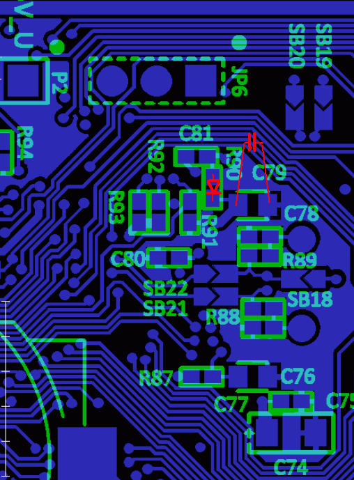
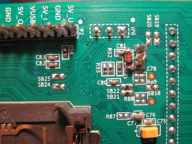
A good thing about the ST devboards such as the DISCOs, is, that ST provides extensive documentation, including schematics, Gerber files and even a detailed BOM - so modding them is relatively easy.
![]()
While we assume enough power for the "normal" run during daytime, there's no reason to waste energy if it can be avoided. So the firmware first initializes the internal RC-oscillator-based clock (MSI) and switches it into 400kHz mode to reduce consumption, which enables to switch from the standard internal regulator to a low-power one. These few simple steps brings basic runtime consumption down to cca 250uA. This can be conveniently measured by removing the jumper from JP5 and routing an ammeter from any of the outer pins to the middle pin - the middle pin of this jumper connects directly to the mcu's VDD; the ON position pin goes from the onboard current measurement and the OFF position pin is directly the power supply input bypassing the current measurement (using the onboard extra microcontroller for measuring current involves talking it through I2C in a protocol which is not very well described and has to be mostly extracted from the demo sources, so I left it for another time).
Then the firmware checks, if the 32.768kHz LSE oscillator is already running and if RTC is enabled - if yes, everything is left as it is; if no, the oscillator is started, RTC enabled and initialized. There is no provision to adjust time, yet; the joystick on the DISCO board is to be used for this purpose.
Then the LCD is initialized, and then the main loop is entered. In it, the current time is read out of RTC and displayed, and then the mcu goes to sleep until the RTC ticks and wakes it up - this further reduces consumption to some 50uA. Even lower levels of consumption should be possible to be achieved, down to maybe some 10uA (including the LCD's consumption), but this should be enough for the first experiments.
I then took a solar cell salvaged from an commonplace solar lantern, with moderate illumination this one easily achieves 2-3V, sufficient to run the module. As the RTC consumes around 300-500nA (depending on voltage, but also on the particular crystal and surrounding circuitry), the 3x10uF capacitors, after being fully charged, should be able to supply it for cca 100 seconds or roughly 2 minutes (the RTC works down to 1.5V, and the current consumption with voltage is nonlinear, so endurance is slightly longer)
-
Hope, revisited
07/15/2018 at 22:32 • 0 commentsA couple of days ago, two of my friends - independently - discussed projects involving relatively large but precise (low leakage, low temperature coefficient, etc.) capacitors. Both expressed concern about dielectric absorption (DA) being potentially detrimental for their applications.
DA is one of those pesky "secondary effects" which make our parts so different from the ideal ones. The most dramatic way how it demonstrates itself is when charged capacitors are discharged momentarily, and then without outside source they "regain" part of the voltage they were charged into. DA is caused by charges trapped in quantum states with relatively long release time - contrary to "elastic" dipoles which are behind the "classical" permeability of the dielectric and which act "instantaneously" with applied electric field, making up a "perfect" capacitor (up to a certain frequency of course). DA is modeled by several series RC, in parallel to the "root" capacitance (plus any "conventional" parasitics, e.g. the resistance representing leakage), with time constants in minutes to hours, and capacitances up to several percents of the "root" capacitance.So, to my friends, I recommended foil capacitors off top of my head, but then remembering Bob Pease's articles on "how soakage in Teflon is way better than Mylar", immediately went to search for solid data. And they are not that easy to find. First of all, there are several types of foil capacitors with different dielectrics, which obviously implies different amount of DA - and long are gone Pease's times with dozens of different foil capacitors; today there are basically only three materials used: polypropylene (PP), a family of polyamides (polyesther terephtalate PET, basically your plastic bottle, that's Pease's Mylar; and polyesther naphthalate, PEN), and polyphenylene sulfide (PPS). There's no polystyrene anymore (probably because of its low melting point, making it unsuitable for modern SMD and RoHS processes), no polycarbonates (maybe the same reason), and no PTFE (Teflon) touted as the best of bests, at least not in the common commercial offerings - they were said to be notoriously hard to process, mainly metallize.
Okay, but how ceramics perform with regard to DA? They were only in nascent state in Pease's times - a plain ceramic disc with two metal foils glued on - and technology made giant leaps in this area in the past few years, with intense research both in dielectrics, and their processing into the MLCC chip capacitors which are commonplace today. Manufacturers understandably tend not to publish more than absolutely minimum data on their parts, and DA is rarely if at all specified. From what I've found, the absorption capacitance for C0G/NP0 ceramics were said to have be around 0.5%, whereas PPS foil was said to have absorption capacitance 0.02-0.05% of the nominal capacitance.
And then I stumbled upon aresearch on ceramic capacitors, performed for NASA by Alexander Teverovsky, and looking at the numerous graphs of current vs. time flowing into or out of a charged/discharged ceramic capacitor, in log-log scale - it finally downed to me:
The manufacturers uniformly quote leakage as current at applied rated voltage, after 120 seconds. But, after 120 seconds, the current is still dominated by the absorption (I_abs in the above graph) ! And, at that point, it's still one or two orders of magnitude higher than the final leakage (I_lk in the above graph).(The second conclusion from Mr. Teverovsky's research is, that the absorption capacitance in X5R and similar high-permittivity capacitors is surprisingly high, tens of percents, typically around 25-30%; again, the difference to the much lower value in other sources - often around a few percents - can again be explained by the "unpatient" standard methodology of measuring DA, with the "discharge momentarily and then let "recover" method", where the "recovery voltage" is measured after 15 minutes, which again is probably one or two orders of magnitudes away from the actual point where the "recovery" reaches its maximum).
In other words, it's quite likely, that the few thousands of MOhm*uF figures given by the manufacturers for the ceramics, may be one or two orders of magnitude off, and that the real "leakage time constant" may be around or above our target 36ks.
As it was only on grounds of these leakage figures we dismissed the ceramics as candidate for a night-long storage, we now can consider them as candidates again. Thus, we can consider the simplest arrangement, the capacitor being charged from the primary source through a low-leakage diode to some 3V and been connected to the RTC directly.
Our estimated capacitance need for the super-low consumption RTC is a few hundreds of uF. 100uF X5R MLCC rated for 4V are readily available in 1210 size for around a dollar apiece and maybe half a dollar at moderate bulk. This is a very reasonable price to pay for a gadget to last a century.
There is hope. -
The HV solution, in painful details.
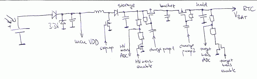
07/14/2018 at 14:44 • 0 commentsSo storing energy for RTC in a PP foil capacitor, utilizing its high-voltage properties, would mean to build something like this (the controlling mcu, as proposed to be STM32L476, not drown here):
![]() The solar panel on the left would keep charged a low-voltage capacitor, and the mcu would be powered from that point. That's why a 3.3V Zener is added, to avoid overvoltage. This is the simplest arrangement, although different ones are certainly possible, allowing that point to go as high as the solar panel would go and powering the mcu through a 3.3V LDO capable of efficiently bypassing itself on low input voltage (this unfortunately is not an often advertised property of a LDO, so this may need investigation, too, and maybe some more innovative circuitry). Another possibility is to use a series resistor and a shunt regulator (or simply a Zener diode) for supplying the mcu, or a more or less sophisticated step-down. The mcu is not going to execute too much code, and is anticipated to run in a power-efficient mode, with power consumption probably way below 1mA, so the series resistor-Zener combination may be entirely sufficient.
The solar panel on the left would keep charged a low-voltage capacitor, and the mcu would be powered from that point. That's why a 3.3V Zener is added, to avoid overvoltage. This is the simplest arrangement, although different ones are certainly possible, allowing that point to go as high as the solar panel would go and powering the mcu through a 3.3V LDO capable of efficiently bypassing itself on low input voltage (this unfortunately is not an often advertised property of a LDO, so this may need investigation, too, and maybe some more innovative circuitry). Another possibility is to use a series resistor and a shunt regulator (or simply a Zener diode) for supplying the mcu, or a more or less sophisticated step-down. The mcu is not going to execute too much code, and is anticipated to run in a power-efficient mode, with power consumption probably way below 1mA, so the series resistor-Zener combination may be entirely sufficient.
The front-end could involve also a standalone "harvesting-optimized" step-up, so that operation can start at sub-volt outputs of the solar panel - the chosen mcu starts at 1.8V. But this in practice is not such an issue, as solar panels can be connected in series to boost their output voltage at low illumination, if needed.
The mcu, when input voltage allows it to run, would measure the current state of charge of the "HV storage" capacitor by switching on the divider and measuring the voltage on it; then, as necessary, it would start pulsing the output driving the step-up transistor. From occasionally measuring the input and output voltage of the step-up, the mcu can calculate the needed number of "boost pulses" to reach the maximum design voltage of the "HV storage" capacitor, and then simply let a timer to produce the needed pulses, while the rest of the mcu can go to power-efficient "sleep".
While the "HV storage" capacitor charges, on the load side, measurement of the HV voltage and target/holding capacitor volrage before and after a transfer of "bucketful" of charge provides the calibration data needed for running the step-down when primary power is not available. These have to be stored somewhere - the lowest consumption "Shutdown" mode of the mcu, the RAM is powered down and does not retain its content. So, during/after calibration, the data need to be stored in the FLASH (which, given the modern 32-bitters don't have an integrated EEPROM is sort of an annoyance, causing the program stop for the duration of write, and also presents surges of relatively high power consumption); in an external EEPROM or similar (which again is an annoyance, as we need these data during low power operation, thus we don't want to power an extra IC nor want we to burn power during the lengthy communication with it); or, the best solution, if there is not too much calibration data (i.e. if we can piecewise linearize the data or find a simple algorithm to calculate needed pulse rate, given certain state of charge of the "HV storage" capacitor, and calculate how this charge changes in time), we can store them in the 32 32-bit Backup Registers which are part of the RTC and are powered together with RTC.
When primary power ceases, the mcu has to calculate the next period after which stepdown has provide a "bucketful" of charge to the holding capacitor, program the RTC to wake up the mcu after this period, and go to the "Shutdown" mode. After waking up, this process has to be repeated. From time to time, the mcu might need to measure the state of charge of the "HV storage" capacitor and maybe also the state of the "holding" capacitor, to readjust for any drifts.
As the mcu has to be powered during the no-primary-power period together with the RTC, both the RTC power supply pin (VBAT) and the mcu power supply pin (VDD) have to be connected; so the internal switch which isolates VBAT from VDD while VDD is low, here can't be used. The "mcu VDD" and "VBAT/RTC" nodes in the schematics above in fact represent "high-power-VDD" and "low-power-VDD", and are to be connected through a low-leakage swithing fabric - maybe merging them through two low-leakage diodes would suffice, as the currents involved are low. There also has to be also a means to notify the mcu that there is sufficient "high power" - one way to do this would be to use a voltage detector IC (traditionally used to provide reset in past times when voltage detectors were not commonly built into mcus) connecting its output to a digital interrupt input of the mcu (the raw input volage can't be used, as voltages around VDD/2 on digital inputs may cause increased power consumption).
It is clear that such a project, involving both nontrivial electronics and nontrivial software, with a bunch of unknowns ahead, is not something one is going to whip up during a couple of spare weekends between workdays paying the bills. So, at this point, I was about to give up... -
Non-chemical storage: is there hope?
07/13/2018 at 07:25 • 0 commentsThe key issue in maintaining RTC operation during "no power period" (night in case of using solar power) is storage of sufficient amount of energy. We excluded parts based substantially on chemical processes (accumulators, supercaps, electrolytics) because of their inherent lifetime limitations, and ceramic capacitors on grounds of their relatively high leakage, preventing them to keep charge beyond a hour or so. So what we're left with is the finest kind of foil capacitors, namely the polypropylene ones, which exhibit the lowest leakage of all commercially available capacitors.
However, PP capacitors are expensive per microfarad, and they are bulky, too. From the charge equation:
assuming that a CMOS RTC will work in a cca 2V-3V supply power span (i.e. a 1V voltage drop), the required time from dusk to dawn is around 10 hours i.e. 36ks, and the current consumption is 40nA, and applying a snippet of optimism (i.e. that there are no other significant leakages) the required capacitance is around 1.5mF. In commercially available PP foil capacitors, available in capacitances up to few tens of uF, that converts to hundreds of euros/dollars, which - even taking into account that we might spend somewhat more on a clock which will never need batteries, maintenance, nor replacement - is more than we might be willing to spend. That the sheer volume of such capacitor battery may be larger than we would like to allocate for a clock, is another (albeit slightly less important) negative factor.
So is there any hope we might ever accomplish our task?
It's time to start to think a bit out of the box.
What is the reason why foil capacitors are bulky and expensive, compared to other types of capacitors? Price is given by the amount of material used times the cost of material, plus the cost of time/labour spent on preparing them. As the first factor is of the same reason as the "bulkyness", let's have a look at it first. Given similar thickness of the needed metallic contact layers, capacitance-to-volume ratio is given by the basic properties of capacitors: permittivity of the dielectric layer, its thickness versus breakdown voltage, and its area. Electrolytics and tantallum are unbeatable in volumetric efficiency because of they employ a "trick" to increase the latter two to its extremes: dielectric area is increased several orders of magnitude above the basic area of electrodes by creating a "spongy" structure using various methods, and the dielectric is "grown" electrochemically to exactly the minimum thickness needed for a given breakdown voltage. That the bulk of capacity of elyts/Ta is given basically by "growing" also decreases manufacturing cost per microfarad. High capacitance ceramic capacitors employ a high permittivity material, sandwiched with metal foils to a multilayer structure in huge sheets, which is then cut up into thousands of individual parts, so there is significant parallelism in making them (and, given the huge demand for them, they are manufactured in highly automated way which drives down the manufacturing costs too). Foil capacitors can do neither of these: the plastics have a relatively low permittivity, they are based on thin plastic foil and their breakdown voltage is given by the thickness of the foil so it has to be perfectly smooth and flat and any "sponginess" is excluded. Then they are metallized, wound up and packaged, and while there may be some amount of parallelism and automation applied, it's way lower than at the other types of capacitors.
So in capacitance the foil types simply can't beat other types. Do they have some other distinguishing feature then, which could be utilized?
The fact is, that foil capacitors are good at insulation voltages. So good, that PP capacitors rarely have rated voltage below 100V. Can't we utilize this fact?
So far, we asumed, that in the RTC "emergency supply" line there is no active electronics, just the capacitor, charged through a switch (diode) from the primary power supply. So let's give up this simplistic view and let's assume we can use a capacitor charged to tens of volts. We would need a step-up on the charging side first, but as we assume there's relatively plenty of energy on that side, that's then a comparatively simple task. What is going to be a challenge is a stepdown "voltage regulator" on the RTC side, and one with quite unusual requirements:
- high voltage input (tens of V, if possible, up to 100V)
- low voltage output (2V-3V)
- low current (up to 1uA)
- extremely low self-consumption (sometimes called quiescent current, but sometimes this name confusingly denotes a different parameter - consumption while the regulator is off/disabled)
- high permissible output ripple (2V-3V output, ie. 1V ripple, is quite okay)
It's very unlikely there is any commercial offering with these parameters. Usually it is assumed, that high voltage input implies an off-grid or similar primary source, i.e. that once there's voltage, there's power. Also, high-voltage electronics is exceedingly rare these days, and searching for "high voltage input" often returns parts rated with input voltages only slightly higher than 5V... When it comes to rare and exotics, Linear (having been gulped by Analog) and Maxim come into mind, but the best I could find was LTC3255, but that works out of that premise above and has near zero efficiency at the higher voltages input...
The primary idea towards the required stepdown is to use a charge pump, decreasing voltage by transferring small amounts of charge using a relatively small transfer ("bucket") capacitor, into a much larger output capacitor. The ratio of capacitances should be set so, that one "bucketful" of charge from the fully charged input capacitor (i.e. 100V) should not increase the output voltage by not more than the maximum ripple, i.e. 1V - that gives us straighforwardly a 1:100 "bucket":"holding" capacitance ratio.
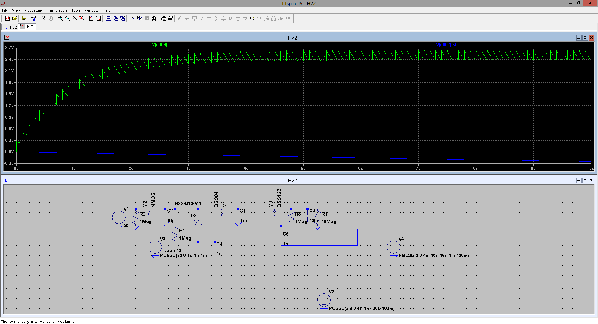
The following simulation illustrates the idea:
![]()
Green line is voltage on the "holding" capacitor (thus the target RTC power supply), blue line illustrates decrease of the "storage" capacitor voltage.
V1/R2/M2/V2 on the left simulate the input "stepup" - here only charging momentarily the main "storage" capacitor C2 to 50V. C1 is the "bucket", R4/D3/M1 represent the "high switch" and R3/M3 the "low switch". C3 is the "holding" capacitor and R1 represents the load - here, some 200-300nA, as the simulation was inteded towards using not the "optimal" RTC, but the RTC incorporated in STM32L476.
Note, that both the "bucket" and "holding" capacitors' leakage contribute to the total current, so they have to be of the extremely-low-leakage type (i.e. PP foil), too.
C4 and C5 (together with the "bleeding" 1M resistors R4/R3) are primitive level shifts for the MOSFETs, driven by the "control electronics", represented here by voltage pulse sources V2 and V4. As for a homemade project it's unlikely I will be able to get manufactured my own low-leakage CMOS control IO, the plan is for prototype to use the STM32L476 in its lowest-consumption mode, being periodically woken up by the RTC so its generates the needed pump-pulses on two of its inputs and then goes to sleep again. This would increase its consumption to roughly twice as much, but it still would be viable for a proof-of-concept.
To reduce self-consumption further, the idea is to omit "immediate" feedback. Feedback involves a voltage divider, a comparator and a source of reference voltage, all these being hungry for power we don't have. OTOH, we settled for higher ripple, so the idea is, that the charge pump would run most of the time in a "purely digital" manner, using calculation to estimate the remaining voltage on the "storage" capacitor, and from that - as the "bucketful" of charge decreases with decreasing input voltage - the needed time between "pump-pulses". To avoid problems with unknown tolerances of used parts, the calculation may be calibrated against measurement beforehand, while there is enough input power - the mcu comes handy here.There may be an occasional feedback, with dividers well-isolated by low-leakage MOSFETs, switched on only rarely and only for the absolutely necessary time of measurement - both during calibration and "runtime".
This whole arrangement is apparently complex, employing nontrivial electronics plus software, and obviously ridden with a large number of potential pitfalls.
So, may there be any other, simpler way?
-
The clock
07/12/2018 at 00:04 • 0 commentsBefore delving into the details of chemistry-less hours-lasting storage, first, the clock itself.
Let's make at least this thing simple. I am going to use a STM32L476-DISCO board. This is based on the STM32L476VG microcontroller, which is member of a low-power 'L4 mcu family by ST Microelectronic. The chip contains both a built-in RTC (with an oscillator for the 32.768kHz crystal) and a segment-LCD controller, making it a suitable choice for building a clock. The DISCO board, besides other things, features a 6 x 14-segment LCD, an on-board ST-Link debugger, and also an auxiliary microcontroller with circuitry for measuring the main mcu's current consumption.
There's one more thing making the 'L476 very suitable for our project: the RTC has its own power domain (intended to be powered by a battery, hence the respective pin is named VBAT), and it isolates itself from the main power domain automatically when the main power drops below the power monitor's threshold voltage.
Of course, there are drawbacks, too. The RTC alone, running with the 32768kHz crystal, consumes around 500nA (the exact figure is voltage dependent), which - while in itself impressive and perfectly suitable for all usual practical purposes - is not exactly the lowest current which could be found on the market. As mentioned in the "root" project, there is a commercially available integrated RTC-oscillator-crystal, with order of magnitude less current consumption, at around 40nA.
So, keeping things simple for now, let's just try to run a simple clock on the 'L476, using its RTC; trying to maintain backup for its relatively large power consumption for maybe one or two hours - and if we succeed in this, there's hope that using a less power-hungry RTC may result in the desired night-long endurance.

 The solar panel on the left would keep charged a low-voltage capacitor, and the mcu would be powered from that point. That's why a 3.3V Zener is added, to avoid overvoltage. This is the simplest arrangement, although different ones are certainly possible, allowing that point to go as high as the solar panel would go and powering the mcu through a 3.3V LDO capable of efficiently bypassing itself on low input voltage (this unfortunately is not an often advertised property of a LDO, so this may need investigation, too, and maybe some more innovative circuitry). Another possibility is to use a series resistor and a shunt regulator (or simply a Zener diode) for supplying the mcu, or a more or less sophisticated step-down. The mcu is not going to execute too much code, and is anticipated to run in a power-efficient mode, with power consumption probably way below 1mA, so the series resistor-Zener combination may be entirely sufficient.