Open Green Energy
-
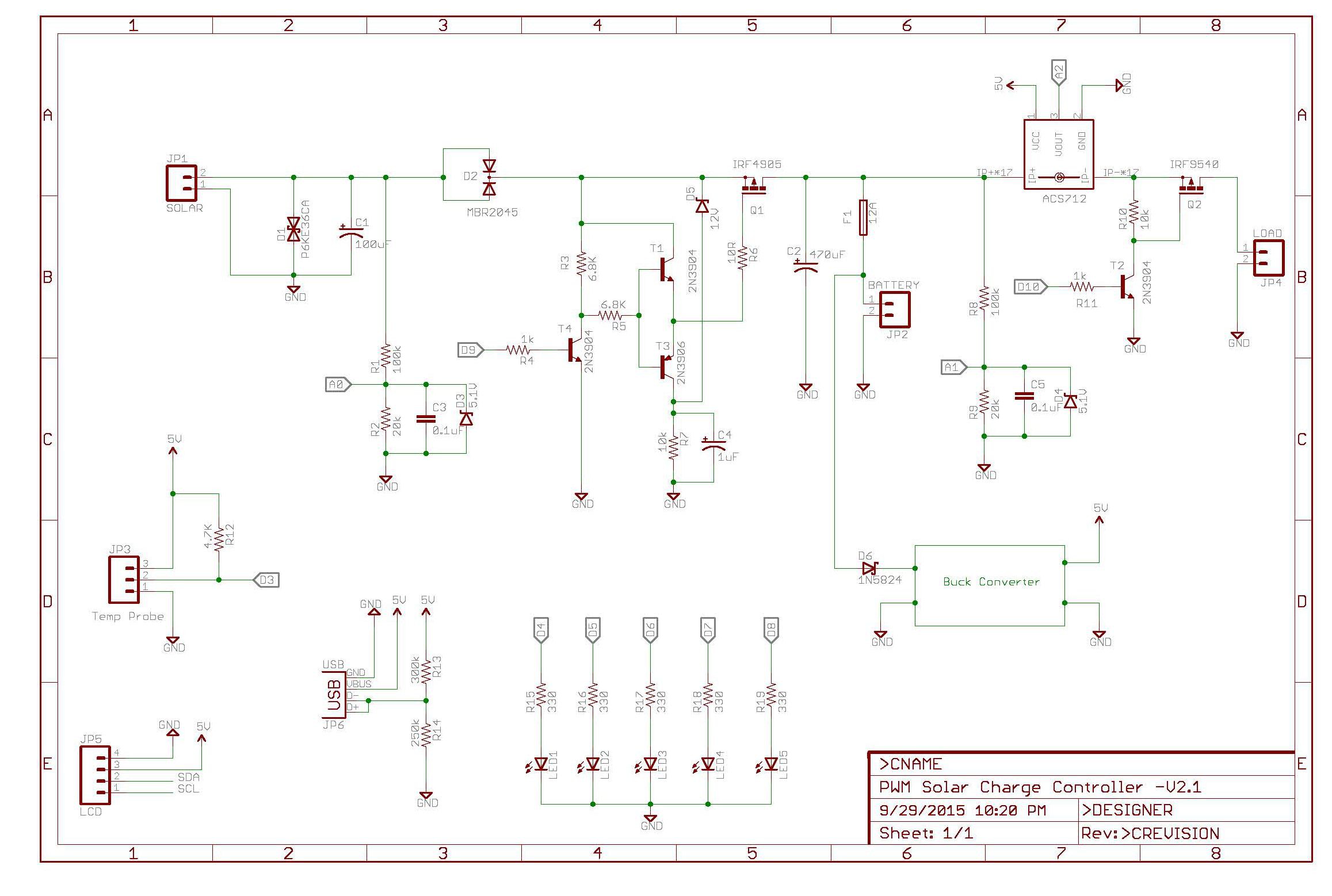
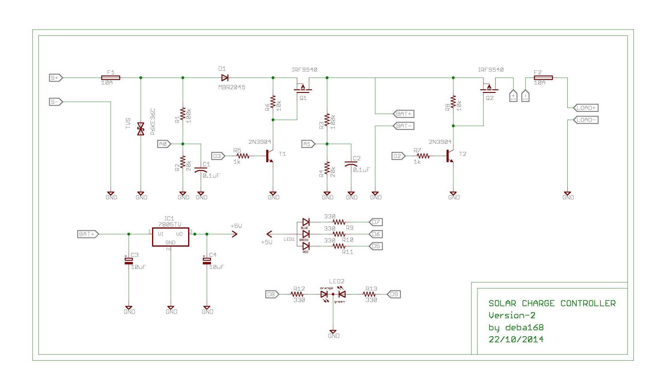
Shematic for PWM Charge Controller V2.1
07/15/2018 at 19:07 • 0 comments![]()
-
Future Planning for PWM Charge Controller - V2.1
07/15/2018 at 19:03 • 0 comments1. The future planning is for V2.1 Charge controller is to implementing 3 stage charging algorithm.
2. Hardware modification for better control
3. Option to implement multi chemistry battery charging
4. Adding a USB port to charge USB charging gadgets like smartphone/tablets.
5. Making a custom PCB for the circuit.
6. Making a 3D printed enclosure for the project.
7. Adding an ESP8266 for remote monitoring through Smartphone App
PWM Charge Controller -V2.1 Algorithm
When the controller is connected to the battery, the program will start the operation.
Initially it checks if the panel voltage is sufficient for charging the battery. If yes, then it will enter into the charge cycle. The Charge Cycle consists of 3 stages.
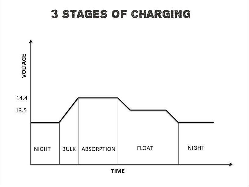
Stage 1 Bulk charge:
Arduino will connect the Solar Panel to the battery directly ( 100 % duty cycle). The battery voltage will increase gradually. When the battery voltage reaches 14.4V, stage 2 will begin.
In this stage current is almost constant.
Stage 2 Absorption charge:
In this stage Arduino will regulate the charging current by maintaining the voltage level at 14.4 for one hour. The voltage is kept constant by adjusting the duty cycle.
Stage 3 Float charge:
The controller generates the trickle charge to maintain the voltage level at 13.5V. This stage keeps the battery to be fully charged. If battery voltage is less than 13.2V for 10mins,
The charge cycle will be repeated.
Load Control:
In the evening, when the PV voltage level falls to +8V for 5mins, the controller will turn on the light. In the morning when the PV voltage is larger than battery voltage for 3mins, the light will be turned off.
Low Voltage Disconnect:
The charge controller will disconnect the load from the battery at LVD point, 11.5V.
Low Voltage Reconnect:
Once the load is disconnected, it will reconnect again only when the battery voltage is more than LVR point, 12.5V
Set point values
Float set point: 13.5
Bulk set point: 14.4
Charge Restart set point: 13.2
Absorb time limit: 1 hour
Charge restart time limit: 10 minutes
Offset for AGM (vs flooded): -0.2
Low voltage disconnect: 11.5
Low voltage reconnect: 12.5
Temperature compensation: -20 mV / degree C
-
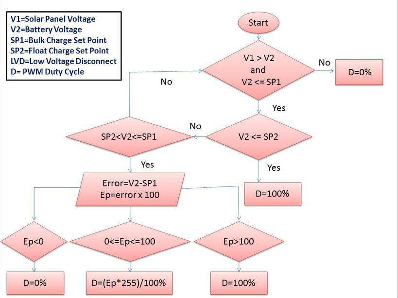
Charging Algorithm
07/13/2018 at 09:25 • 0 comments![]()
![]()
1.Bulk :At this mode, a preset maximum constant amount of current (amps) is fed into the battery as no PWM is present. As the battery is being charged up , the voltage of the battery increases gradually
2. Absorption: When the battery reaches the bulk charge set voltage, the PWM begins to hold the voltage constant. This is to avoid over-heating and over-gassing the battery. The current will taper down to safe levels as the battery becomes more fully charged. 3. Float: When the battery is fully recharged, the charging voltage is reduced to prevent further heating or gassing of the battery
This is the ideal charging procedure.
The present charge cycle block of code is not implements 3 stages charging.I use a easier logic in 2 stages.It works good.
I am trying the following logic for implementing the 3 stages charging.
Future Planning for Charging Cycle :
The bulk charge begins when solar panel voltage is larger than battery voltage. When the battery voltage reaches 14.4V, absorption charge will be entered. The charging current will be regulated by PWM signal to maintain the battery voltage at 14.4V for one hour. Float charge will then enter after one hour. The float stage generates a trickle charge to keep the battery voltage at 13.6V. When the battery voltage falls below 13.6V for 10mins, the charging cycle will be repeated.
-
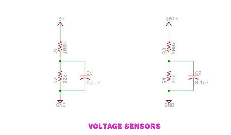
Sensors Calibration
07/13/2018 at 09:23 • 0 commentsVoltage Sensors :
5V = ADC count 1024
1 ADC count = (5/1024)Volt= 0.0048828Volt
Vout=Vin*R2/(R1+R2)
Vin = Vout*(R1+R2)/R2 R1=100 and R2=20
Vin= ADC count*0.00488*(120/20) Volt
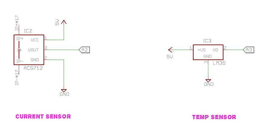
Current Sensor:
As per seller information for ACS 712 current sensor
Sensitivity is =100mV / A =0.100V/A
No test current through the output voltage is VCC / 2= 2.5
ADC count= 1024/5*Vin and Vin=2.5+0.100*I (where I=current)
ADC count= 204.8(2.5+0.1*I) =512+20.48*I
=> 20.48*I = (ADC count-512)
=> I =(ADC count/20.48)- 512/20.48
Current (I) =0.04882*ADC -25
More details on ACS712
Temperature Sensor :
As per data sheet of LM35
Sensitivity=10 mV/°C
Temp in deg C =(5/1024)*ADC count*100
Note : The sensors are calibrated by assuming the arduino Vcc= 5V reference.But in practical it is not 5V always.So there may be chance of getting wrong value from the actual value.It can be solved by following way.
Measure the voltage between arduino 5V and GND by a multimeter.Use this voltage instead of 5V for Vcc in your code.Hit and try to edit this value until it matches the actual value.
Example: I got 4.47V instead of 5V.So the change should be 4.47/1024=0.0043652 instead of 0.0048828.
-
Voltage and Current Sensing
07/13/2018 at 09:21 • 0 comments![]()
![]()
1.Voltage Sensor:
The voltage sensors are used to sense the voltage of solar panel and battery. It is implemented by using two voltage divider circuit. It consists of two resistors R1=100k and R2=20k for sensing the solar panel voltage ans similarly R3=100k and R4=20k for battery voltage.The out put from the R1and R2 is connected to arduino analog pin A0 and out put from the R3 and R4 is connected to arduino analog pin A1.
2.Current Sensor :
The current sensor is used for measuring the load current.later this current is used to calculate the load power and energy.I used a hall effect current sensor (ACS712-20A)
3.Temperature Sensor :
The temperature sensor is used to sense the room temperature. I used LM35 temperature sensor which is rated for −55°C to +150°C Range.
-
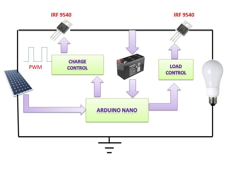
Initial design Idea
07/13/2018 at 09:16 • 0 comments![]()
![]()
The heart of of the charge controller is an Arduino Nano board. The Arduino MCU senses the solar panel and battery voltages. According to this voltages it decides how to charge the battery and control the load.
The amount of charging current is determined by difference between battery voltage and charge set point voltages.
Currently the controller uses two stages charging algorithm.According to the charging algorithm it gives a fixed frequency PWM signal to the solar panel side p-MOSFET. The frequency of PWM signal is 490.20Hz(default frequency for pin-3). The duty cycle 0-100% is adjusted by the error signal.
The future planning is to implement 3 stage charging algorithm.
The controller gives HIGH or LOW command to the load side p-MOSFET according to the dusk/dawn and battery voltage.
Main Functions :
The charge controller is designed by considering the following points :
1.Prevent Battery Overcharge: To limit the energy supplied to the battery by the solar panel when the battery becomes fully charged.This is implemented in charge_cycle() of my code.
2.Prevent Battery Over discharge: To disconnect the battery from electrical loads when the battery reaches low state of charge.This is implemented in load_control() of my code.
3.Provide Load Control Functions: To automatically connect and disconnect an electrical load at a specified time. The load will ON when sunset and OFF when sunrise.This is implemented in load_control() of my code.
4.Monitoring Power and Energy : To monitor the load power and energy and display it.
5.Protect from abnormal Condition: To protect the circuit from different abnormal situation like lightening,over voltage,over current and short circuit etc.
6.Indicating and Displaying: To indicate and display the various parameters
7.Serial Communication: To print various parameters in serial monitor
ARDUINO PWM SOLAR CHARGE CONTROLLER
Arduino based PWM Solar Charge Controller