-
11▇▇▇▇ Timing and Metastability ▇▇▇▇
If electronic components were as perfect as our schematics portray them, we could skip this discussion. But, alas, the real world is never what we wish it to be. Because of real world circuit elements, flip flops have several issues: setup time, hold time, and–more generally–metastability.
![]()
You can see a graphical representation of setup and hold time above. The top trace represents a clock going to three flip flops. The other traces represent inputs going to those flip flops. Inputs to the flip flop must be stable for the setup time before the active clock edge. The inputs also have to stay stable for at least the hold time after the clock edge. The top input (green) is fine. The middle purple one changes during the setup time and the lower trace changes during the hold time. Both of the bottom traces are inviting error. The exact setup and hold times depend on the flip flop you are using. Luckily, when we start using FPGA tools, the tools know about these times and will warn us if it can tell we are not handling these appropriately. The problem is, the tools can't always tell.
Speed Limit
In practice, these times limit how fast the clock can be. Suppose your clock has an active edge every 10ns. If your combinatorial logic feeding the flip flop has a 9ns delay, that should be OK, right? Not if the minimum setup time is more than 1nS. Setup and hold violations are sometimes difficult to troubleshoot, although modern scopes sometimes have special trigger modes to find violations.
If you violate the setup or hold times, the flip flop may go metastable. What this means is the flip flop may behave badly. In some cases it will oscillate or it may take longer to change states than normal.
There are several cases where you have to worry about metastability. One is when you are changing clock domains (that is, feeding a flip flop from another flip flop that uses a different clock). Another problem is when you have data coming from a purely asynchronous domain such as a user input switch or an RS232 port. In that case, there’s no way to be sure the input won’t change within the setup or hold time (or even right on the clock edge).
When you have an asynchronous input you’ll usually cascade it through multiple D flip flops. Each additional flip flop you use reduces the chance of metastability (at the output). However, it also delays the input by a clock cycle for each flip flop.
Learn More
Metastability is a big topic -- too big to fully explore in an introductory bootcamp. There’s a good IEEE paper on the subject.
There are metastability resistant flip flop designs that have a reduced chance of going into the metastable state. These aren’t perfect, though, because you can’t make both the setup and hold times zero. In the end, there’s no substitute for good design.
-
12▇▇▇▇ A Counter ▇▇▇▇
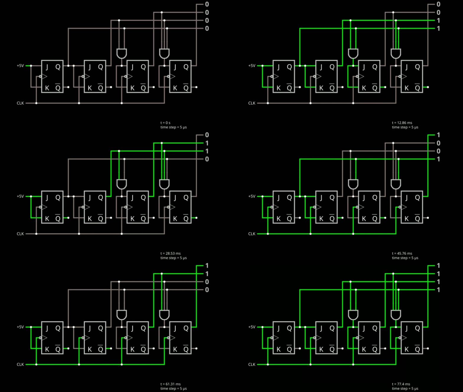
Try this simulation. It shows a four-bit counter constructed from JK flip flops.
![]()
Note the leftmost flip flop has J=K=1 (5 volts) permanently. This makes it a T flip flop that toggles every clock cycle. That's perfect for the least significant bit. The next flip flop only toggles when the previous flop is set to 1. Keep in mind the setup and hold times. The first bit has to be one on the previous clock cycle in order for the second bit to toggle. If you stopped there, you have a perfect two bit counter: 00, 01, 10, 11, 00....
So what about the third bit? It should toggle, but only if the first two bits are 1. Sounds like a job for a two-input AND gate. That's exactly what the circuit does. If you see that, it is easy to understand why there is a 3-input AND gate driving the last flop. If you added a bit, you'd need a 4-input AND gate.
Affairs of State
Many digital logic circuits take the form of state machines. A counter is certainly a very simple state machine. In this case, there are four states: 00, 01, 10, and 11. It just so happens we go from one state to another on every clock cycle and the circuit takes certain shortcuts to get the job done.
A less thought out approach could use four flip flops as a register. Just like the decoder example in the combinatorial logic section, you could decode the state of the flops and use that decoded logic to load the next value into the register. For example, if it were some made up computer language:
if (register = 0000) then register = 0001
if (register = 0001) then register = 0010
if (register = 0010) then register = 0011
. . .
For more complicated states, you may have to do just that. There might also be more complex conditions for what causes the state to change. For example, remember the car wash machine? It had 4 states: 00 for idle, 01 for wash, 10 for dry, and 11 for waiting for car to exit. You might have something like:
state = 00
do forever
// see if we need to start a wash
    if (state=00 AND car_present=1)  then
          state=01
          timer1=5_minutes
          water_on=1
    end if
// keep water on until timer runs out
    if (state=01 AND timer1=0) then
         state=10
         timer2=1_minute
         water_on=0
         dryer_on=1
     end if
// keep dryer on until timer runs out
    if (state=10 AND timer2=0) then
       dryer_on=0
       state=11
    end if
// wait for car to leave
   if (state=11 AND car_present=0) then
       state=0
   end if
end  // do forever
A full discussion of state machines is too much for this introductory bootcamp. But here are a few things to think about. For small state machines it is often easier to use a single bit for each state. So for the car wash, our states might have been 0001 0010 0100 1000. Basically, each state has a 1 that means it is active. This makes decoding easy and helps prevent glitches when going from, say, state 00 to 11. This is so common, it has a name: one hot encoding.
We will look at one more simple state machine -- and it uses one hot encoding -- in the next section. However, if you'd like to read more, there's a Hackaday article you might enjoy.
-
13▇▇▇▇ A Traffic Light ▇▇▇▇
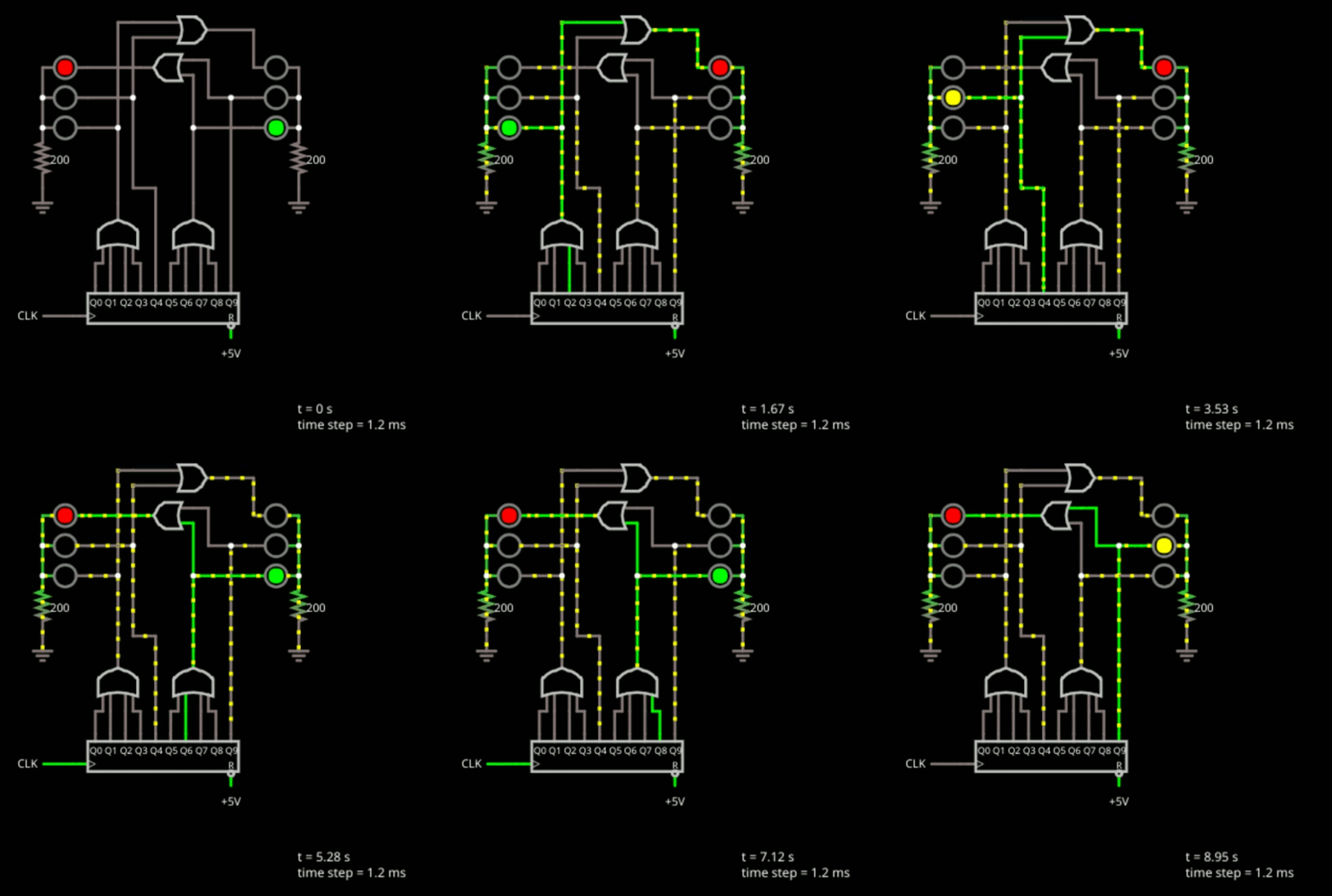
As a final practical digital logic example, consider the simple traffic light shown below.
![]()
This is another state machine. In both cases, the state machines we've looked at all go through their states in order every time. This isn't that unusual, but it also isn't necessarily true in every case, either.
The component at the bottom of the design is a decade counter that simply puts out a rotating one bit, as you can see. There are 10 outputs and each one goes high in turn. This is the one hot state. The clock is set for 1 Hz which is actually too fast for a traffic light, but is good for not being a boring simulation. You could always edit the clock and make it slower, if you like.
The gates are all about decoding the state. The lights stay green for 4 clock ticks, so you can see the first OR gate drives the left green LED and the second OR gate drives the right one.
Logically, if the light is green on one side, it should be red on the other. But, that's not the only time it is red. We want the light to go from green to yellow and while the light is yellow, the opposite light should stay red.
For the left side, state 4 lights up the yellow light. But it also drives an OR gate along with the left green light drive to drive the right red light. The rest of the circuit is a mirror of the first part. State 9 drives the right-side yellow and the left-side red stays red all through states 5-9.
-
14▇▇▇▇ And FPGAs? ▇▇▇▇
You might be wondering what all this has to do with FPGAs? To find out, you'll need to work through the next three bootcamps! However, the things we've looked at in this bootcamp are fundamental to how the FPGAs work internally.
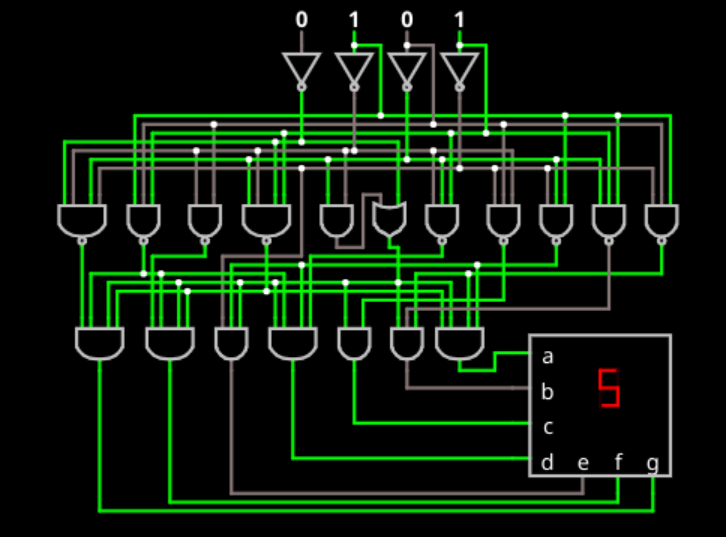
In truth, you can draw schematics and configure many FPGAs. The truth is, though, you don't want to, even if you think you do. All the examples we looked at are pretty simple. But think about something like a 7 segment display decoder. You take four inputs and invert them. Then use AND gates to pick out the ten different digits. Then you use OR gates to drive each segment and merge all the digits that light up a particular segment. Ugh.
Turns out, you can be smarter and figure out that some segments are on in many different cases. That's what the example decoder on the simulator does:
![]()
However, that takes a lot of figuring out, especially if you haven't seen it before. So you either need to spend a lot of time designing it, or you have a very inefficient design. Now think about what the schematic for even a simple AVR, PIC, or ARM processor would look like!
FPGAs use Hardware Description Languages (HDLs) like Verilog to explain what they want done and the computer will go find a good way -- maybe the best way -- to implement it. So our 7 segment decoder can become something like:
if (num=0000) then segs=1111110
if (num=0001) then segs=1100000
...
The HDL compiler will go figure out how to best create that circuitry inside the FPGA. So you might think if you don't need schematics, you don't need logic gates and flip flops, either. But the fact is, the HDL compilers can only make certain things and those things are gates and flip flops, for the most part. Knowing how your design will decompose can really help you in understanding how to get the HDL compiler to do the things that you want to do.
So how do you get started with FPGAs? Go start bootcamp 1 while this is all fresh in your mind and before you know it, you could build that traffic light -- and more -- on an real FPGA.
-
15▇▇▇▇ What's Next? ▇▇▇▇
This has been a pretty grueling bootcamp, but you should now be comfortable with basic logic gates including AND, OR, NOT NAND, NOR, and XOR. You should know about flip flops and the difference between sequential and combinatorial logic. There's plenty more, of course, but this should be enough for you to tackle some pretty good FPGA designs.
But first, take a break! You've earned it! But when you are ready, go on to bootcamp #1 and get started on Verilog and FPGAs.
FPGA Bootcamp #0
If you need a refresher for digital logic before tackling FPGAs, this is the bootcamp for you!
 Al Williams


Discussions
Become a Hackaday.io Member
Create an account to leave a comment. Already have an account? Log In.
Thanks for an excellent series !! Note that the link titled "Open the simulator using this link " is broken. The other links work....
Are you sure? yes | no