MasterOfNull
-
Roll with the changes.
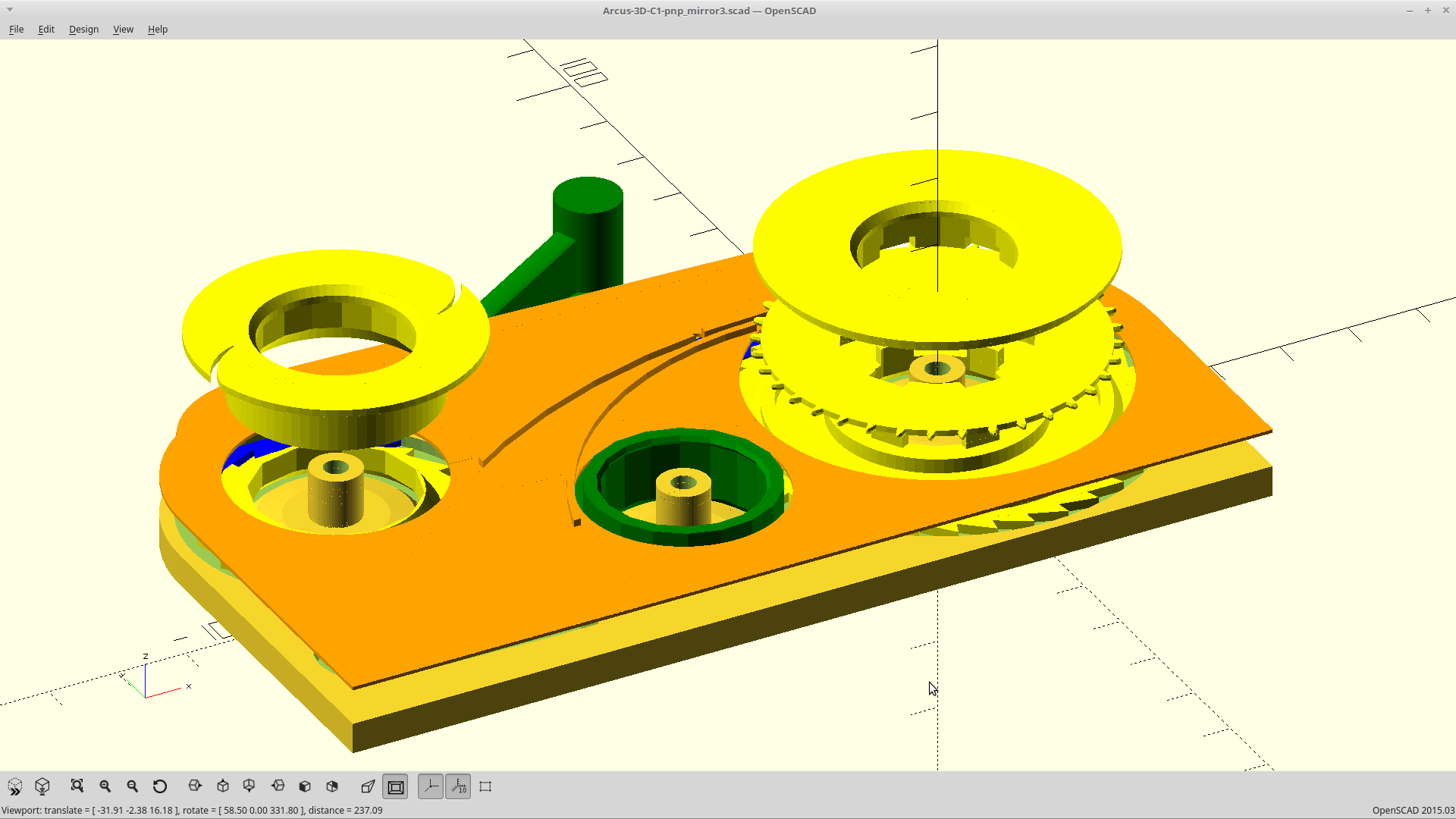
07/20/2018 at 23:57 • 0 commentsThe tape peeling tension was changed from spring tension, to using the friction over the bearing outside.
Also generated cover number one..
![]()
One part left to build.
-
Ooof-da.
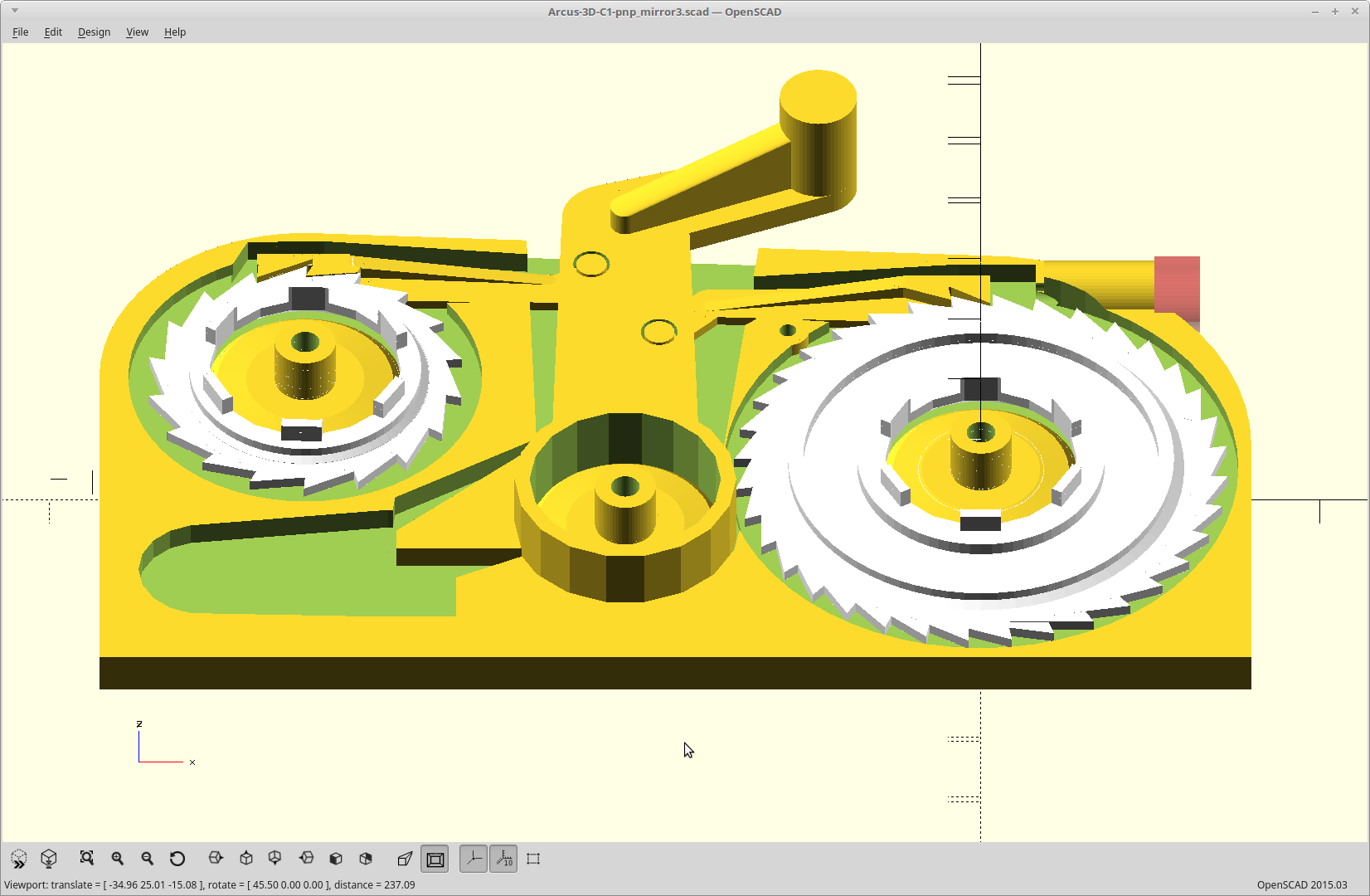
07/20/2018 at 10:32 • 0 commentsWow... that was a lot of work.
![]()
I changed my mind and I'm going to make the cover tape spool slip on the bearing instead of allowing the mechanism to bend in any way. I didn't like how that was looking.
Three parts left to build.
-
And now is the time on Sprockets.
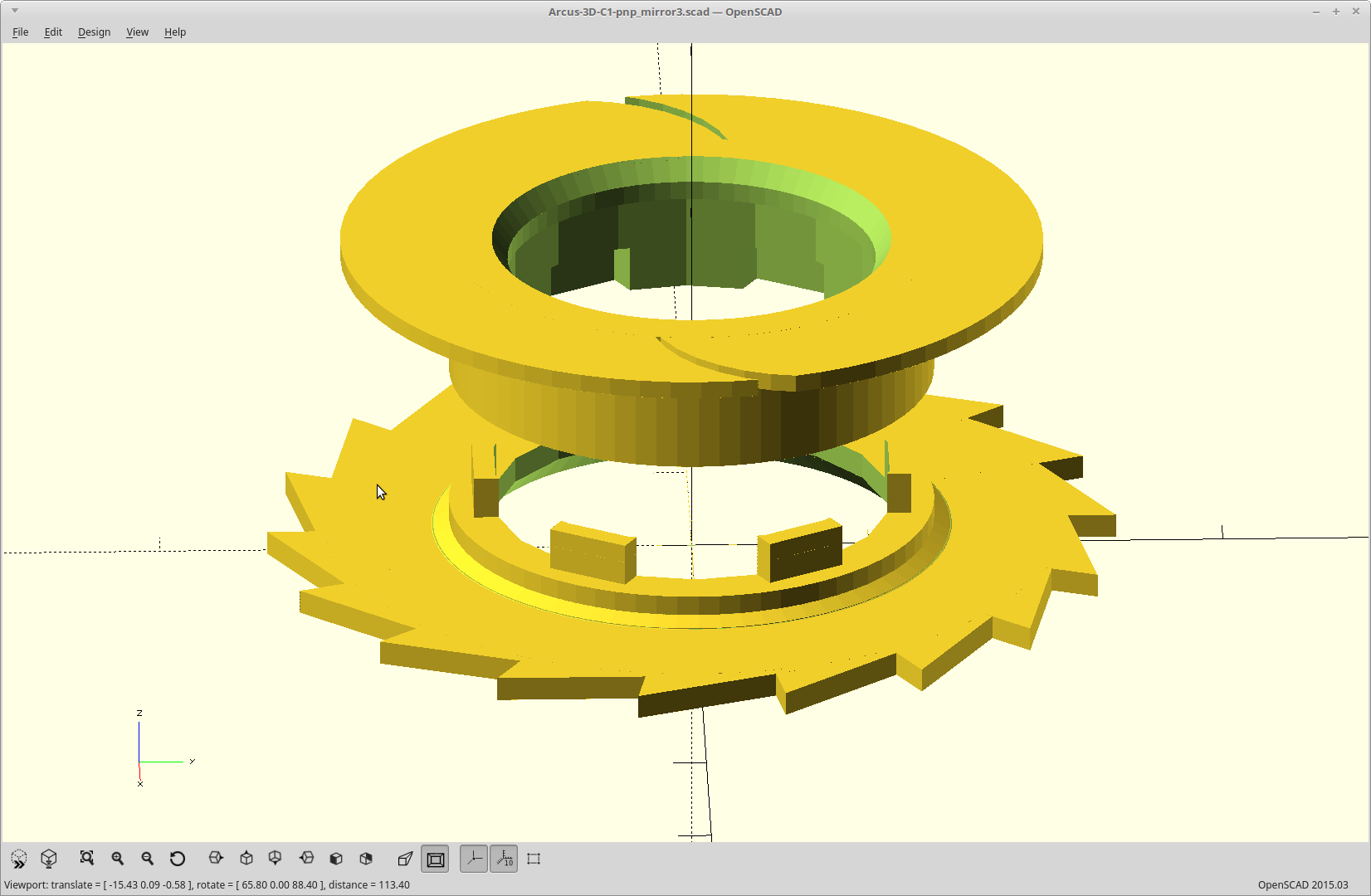
07/19/2018 at 09:14 • 0 commentsI reworked how the sprocket parts fit so inserting the bearing now locks the parts together, and added a positive stop to eliminate alignment issues. It worked perfectly.
![]()
I also took a stab at the cover tape reel. It uses the same tabs which lock the parts together once the bearing is inserted.
![]()
I was envisioning using the backwards stroke to pull the cover tape, and the release stroke to advance the tape (with a positive stop). The logistics of where the ratchet arms need to be may change this and I'm still thinking about it.
The cover tape pull needs to be a longer throw for the ratchet as the reel diameter is smaller and I had planned to exceed the necessary pull by an additional 25%. However, the ratchet driving it would be spring loaded so that once the loose tape is pulled, the spring then takes up the difference.
Or so goes the plan..
-
Welcome, to the machine.
07/18/2018 at 19:20 • 0 commentsThe core part of this idea was a 3D printed drive wheel with a spool supporting both edges of the tape.
I also wanted to implement the cover tape removal using the same motion which advanced the tape, and not require weights or motors to take up the slack.
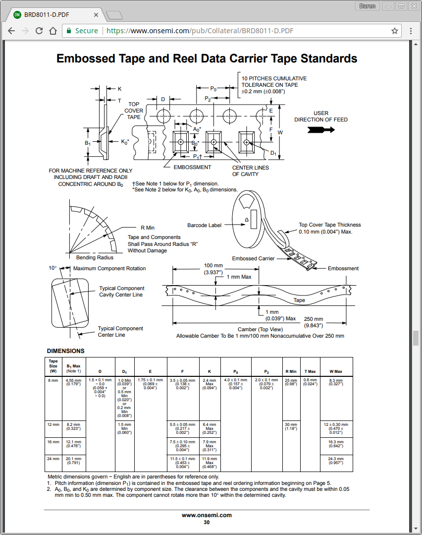
I started by pulling the specifications for the various tape sizes, which is summed up by this page.
![]()
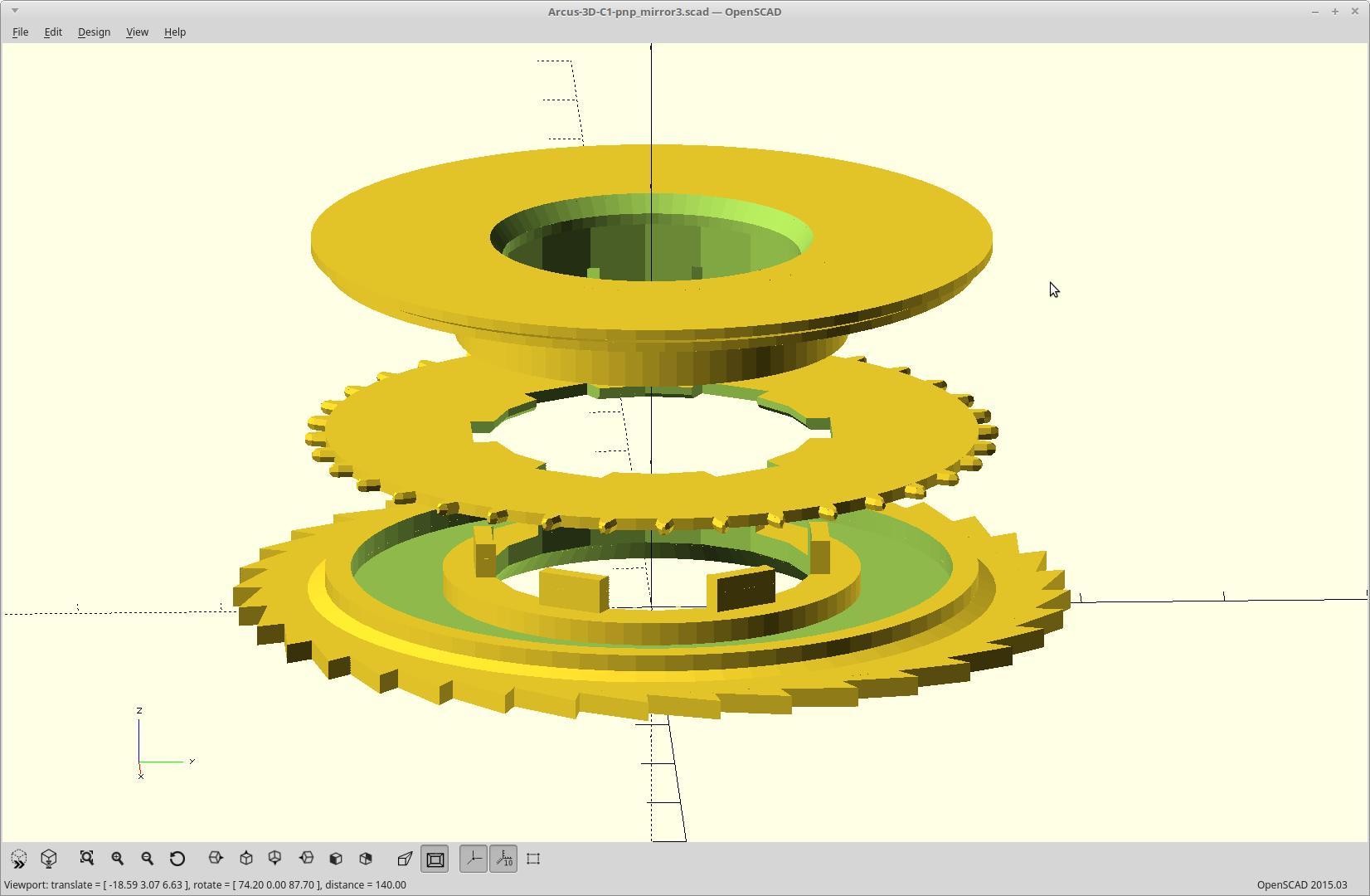
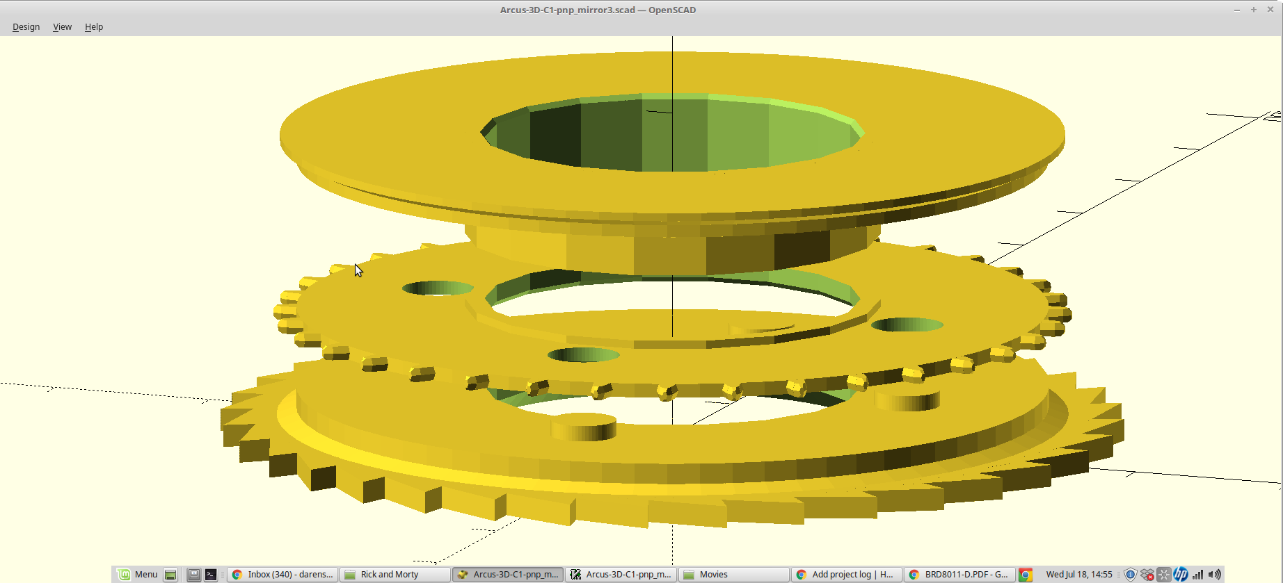
From this I generated 3 parts in OpenSCAD, all of which print flat with no overhangs.
![]()
All three parts are retained in precise alignment by a press fit onto a skateboard bearing. The press fit works over a larger useable range because the center hole was modeled as having flats, by limiting the resolution of the cylinder. Similarly, the drive sprocket was modeled with a cylinder with 2x the number of facets as the number of drive teeth.
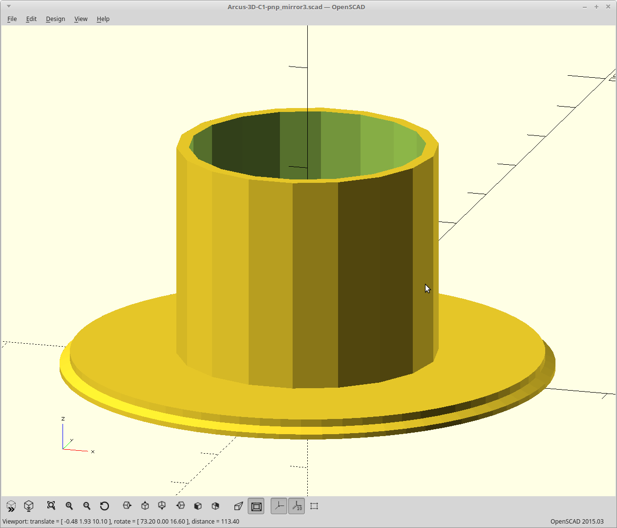
The outer wheels were modeled with a taper to press on both edges of the tape, centering it and forcing it to ride against the bottom side of the cover plate. The wheels are designed to flex slightly at the rim to make up for small variations in tape width.
The idler wheel can be printed in four sizes to accommodate four widths of tapes.
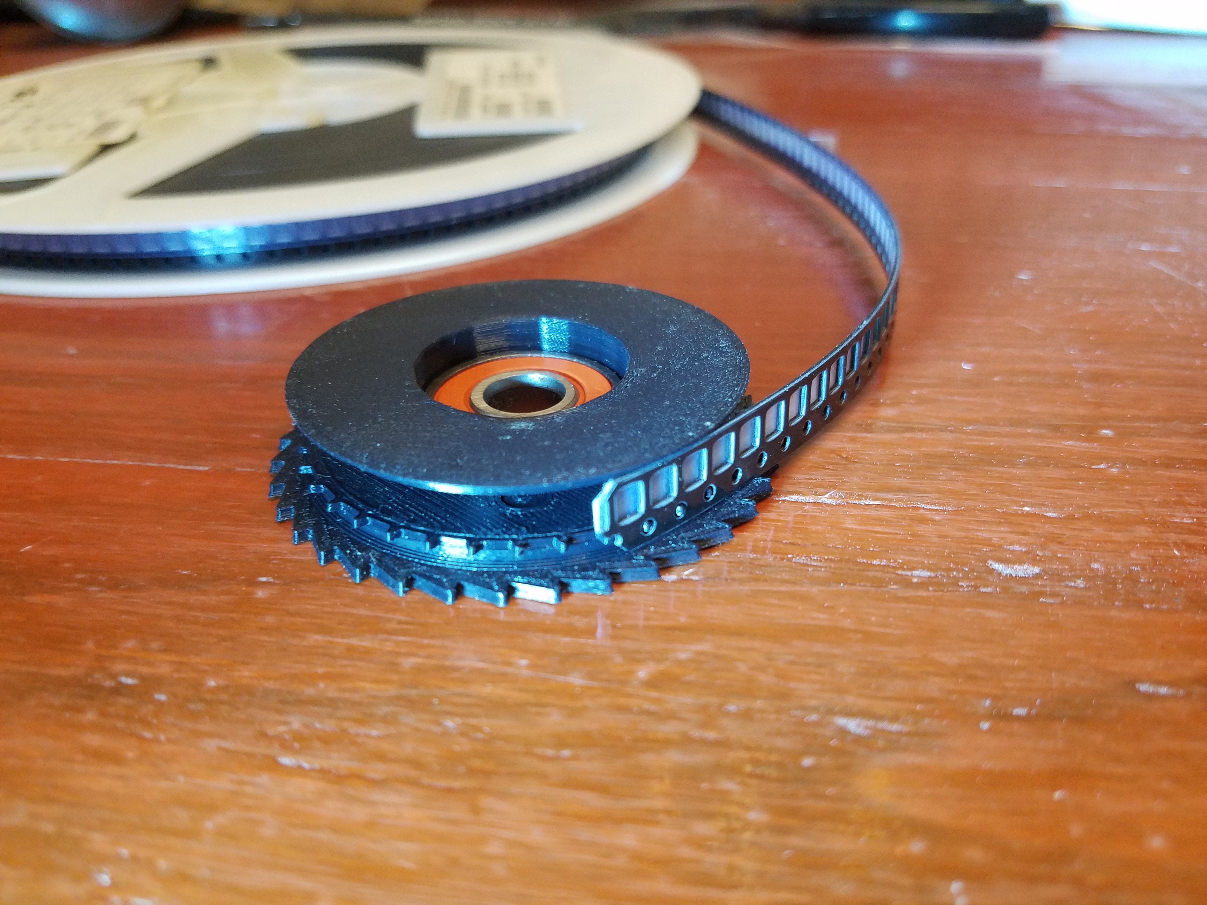
![]()
So the hard part is done. It grabs the tape nicely and the centering works.
![]()
Now to build the rest of the mechanism around that.
P1 - Buddha Tape feeder
3D printable Pick and Place tape feeder for the Arcus-3D-P1.