Ben Hencke
-
Giant Calculator!
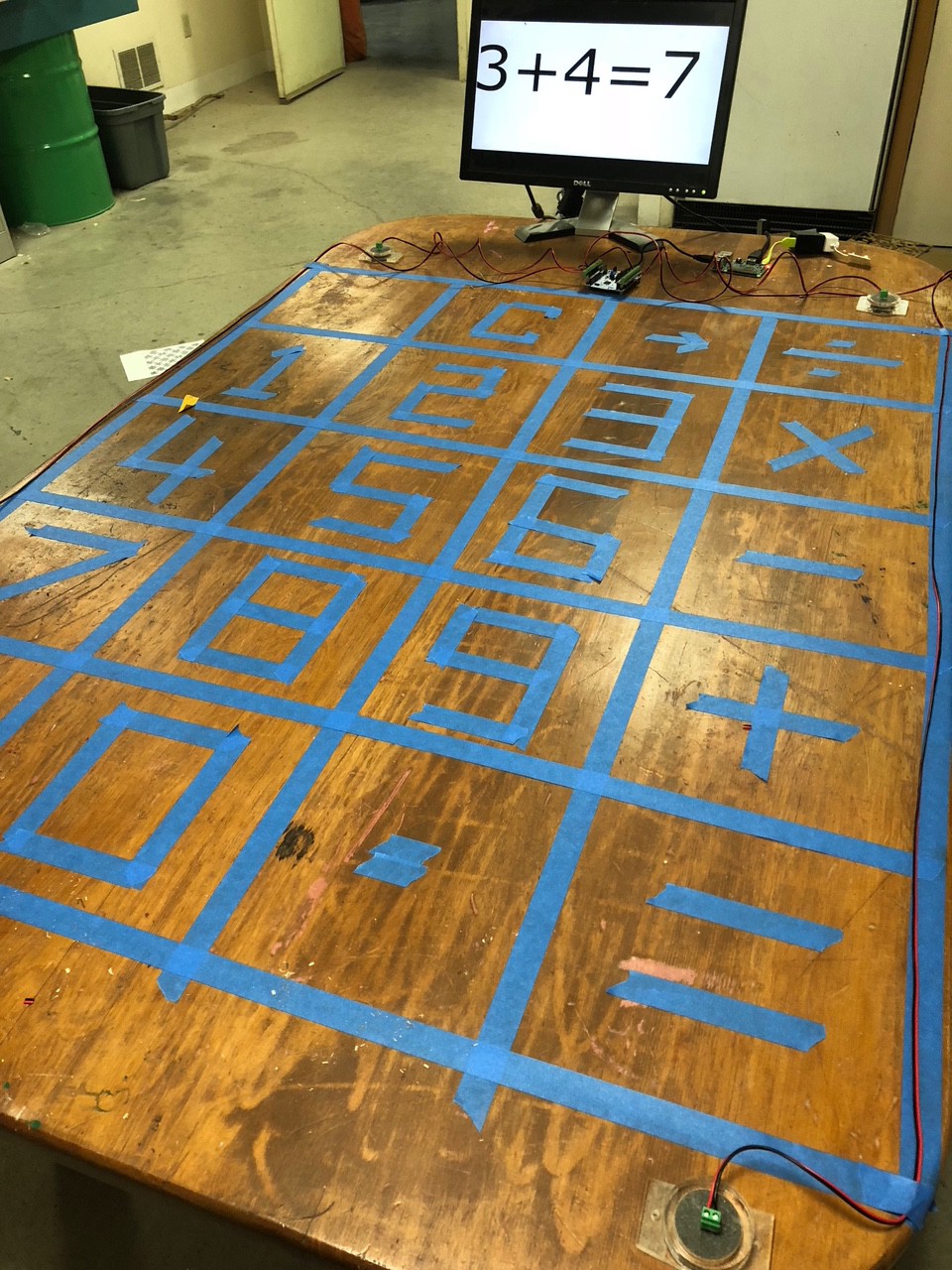
08/28/2018 at 02:20 • 0 commentsWe have kicked around many ideas for this from sports applications to a voting wall and of course combining it with video projection for fun game of whac-a-mole. But today we are going a bit simpler and turning our lunch table into a calculator.
![]()
![]()
![]()
-
Sometimes It's Simple, Sometimes Not
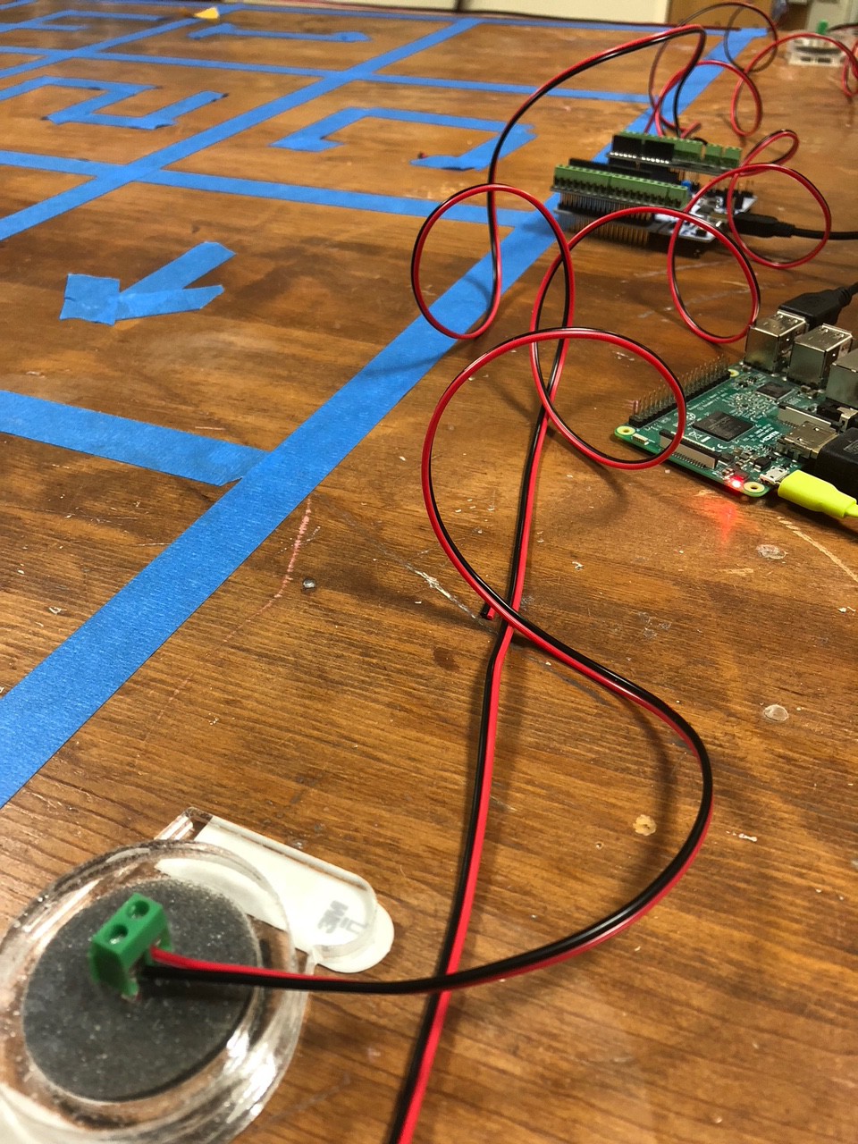
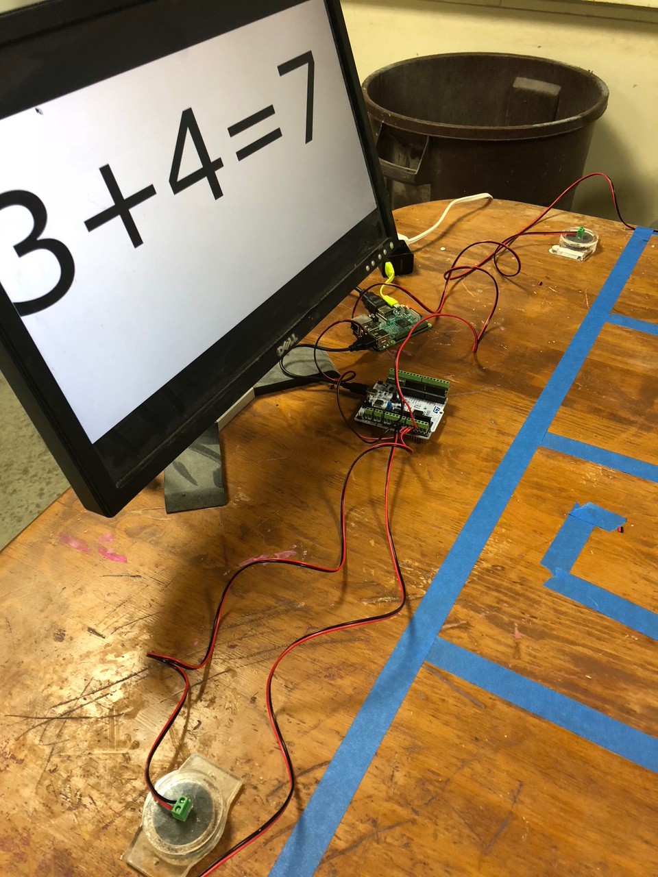
08/24/2018 at 15:02 • 0 commentsLook at this spectrogram. Just look at it.
![]()
I never thought background noise could look so beautiful. Also blue fireballs of signal!
It looks like there are two things going on here. There seems to be a bit of acoustic dispersion - the higher frequencies arrive earlier, and the low frequencies shift in time a bit. There seems to be a jump in the shift at the very low end through, and I still think those are possibly transverse vs longitudinal waves.
But if anything is certain, I need to filter to a smaller vertical slice to get a consistent time delta.
Previous alignments were for equidistant sensors, so things aligned more easily. The various frequency bands hadn't phase-shifted apart.
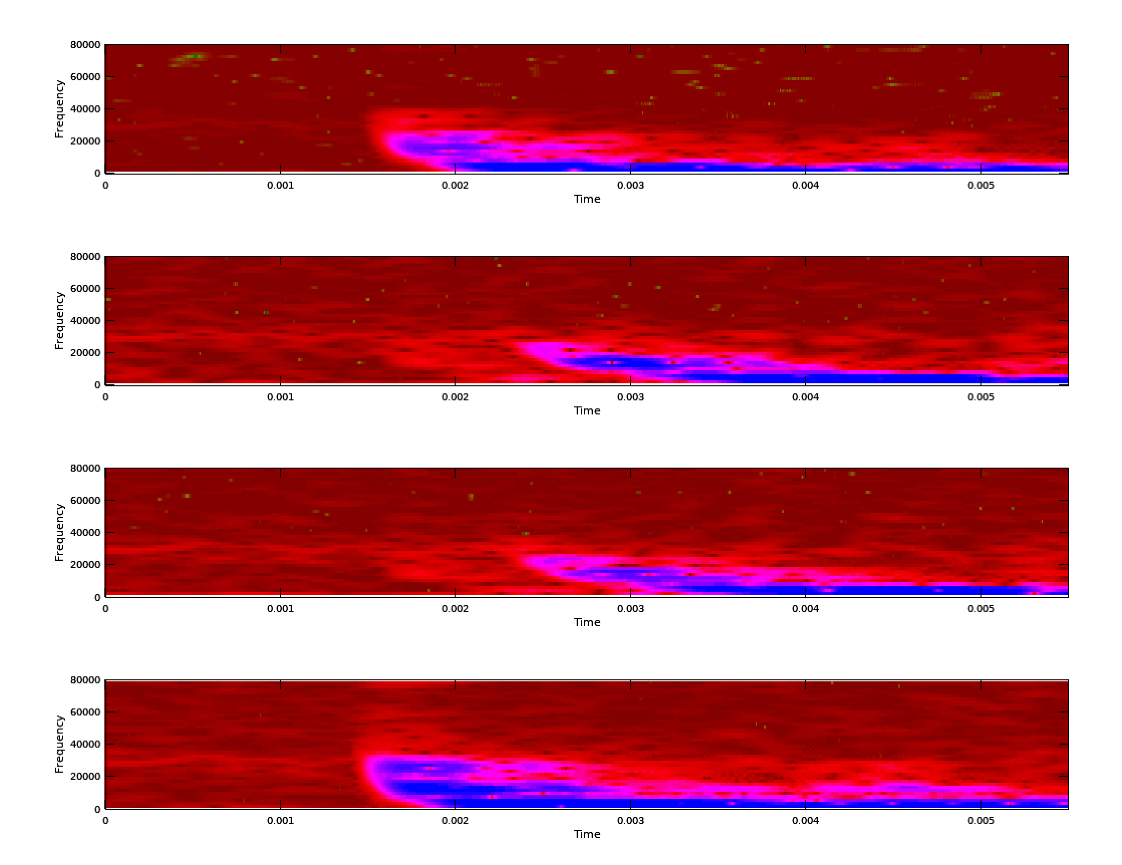
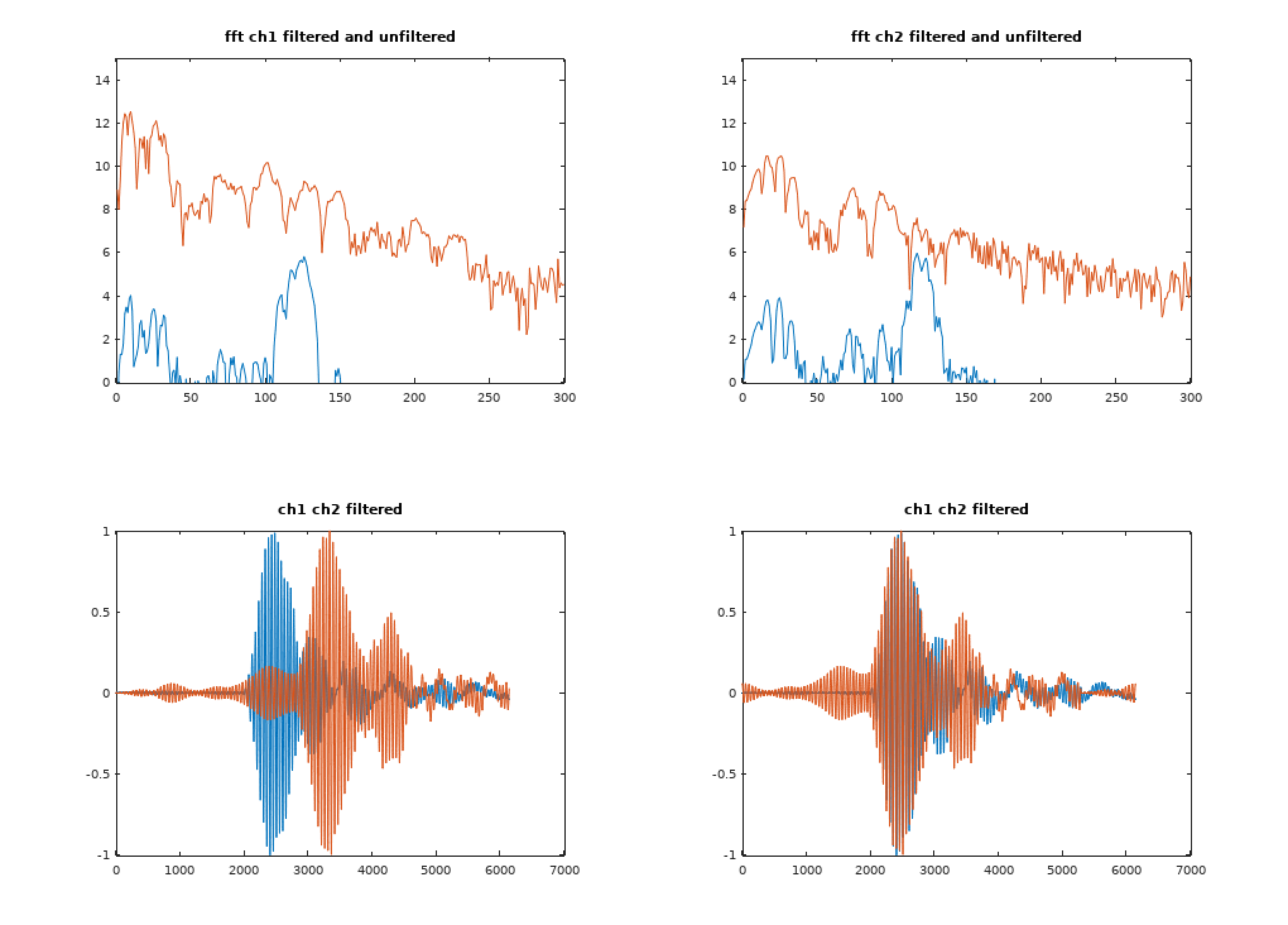
So I tuned the FIR filter a bit, and I'm grabbing stuff right around 20Khz.
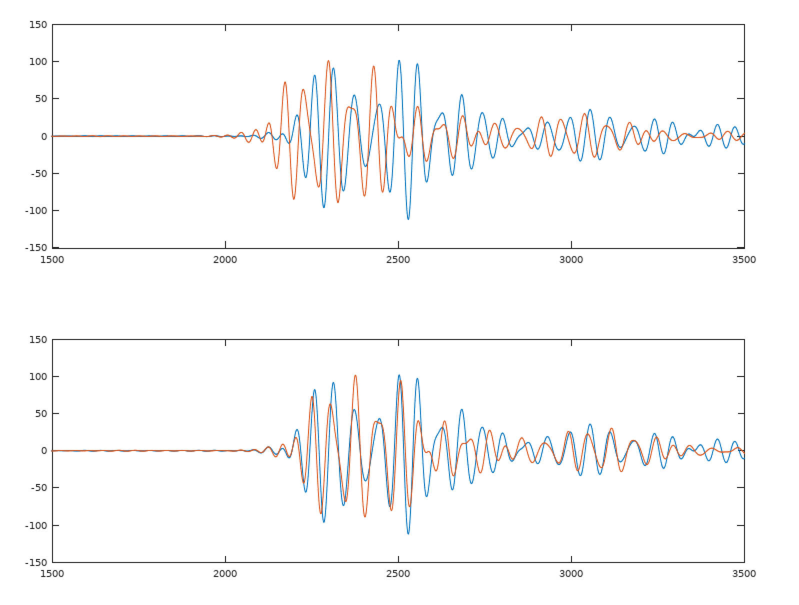
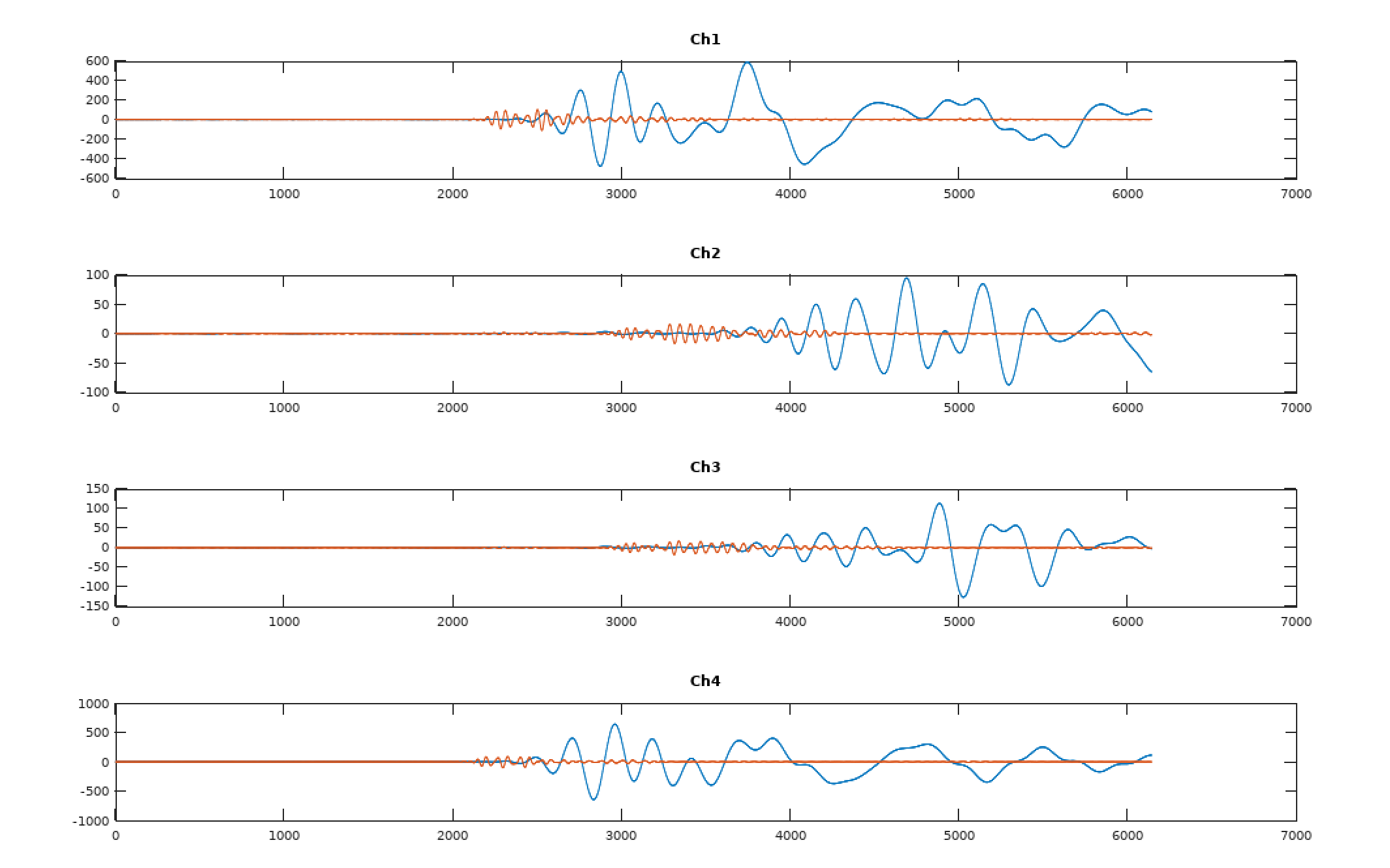
![]()
The top graphs are FFT of a before and after. The bottom are the waveforms before and after cross correlation alignment.
As I move from GNU Octave to the STM32 where resources are tighter, this is lot to crunch across a huge sample. I'd like to keep the number crunching to a minimum, and I don't need/want any alignment of the echoes and other things that happen after the leading pulse.
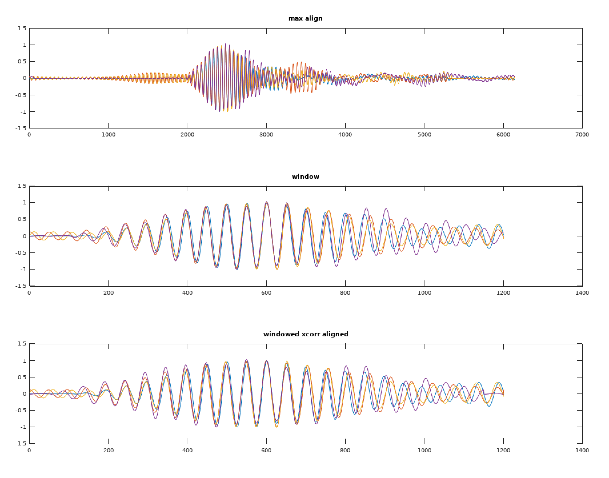
Using peak detection works remarkably well on the filtered signal, but not perfect. Getting a smaller window around the peak and cross correlating that seems to work well.
I tried filtering the full-wave version of the signal through a low-pass, but peak detection on just one half seemed to have similar results, and I plan to use cross correlation anyway as it is going to phase align the waveform phase better than anything else will.
![]()
In most cases the peak-based alignment had the phase within 1 sample of what cross correlation found. You can see it fixed channel 4 (purple) above that was 1 period off.
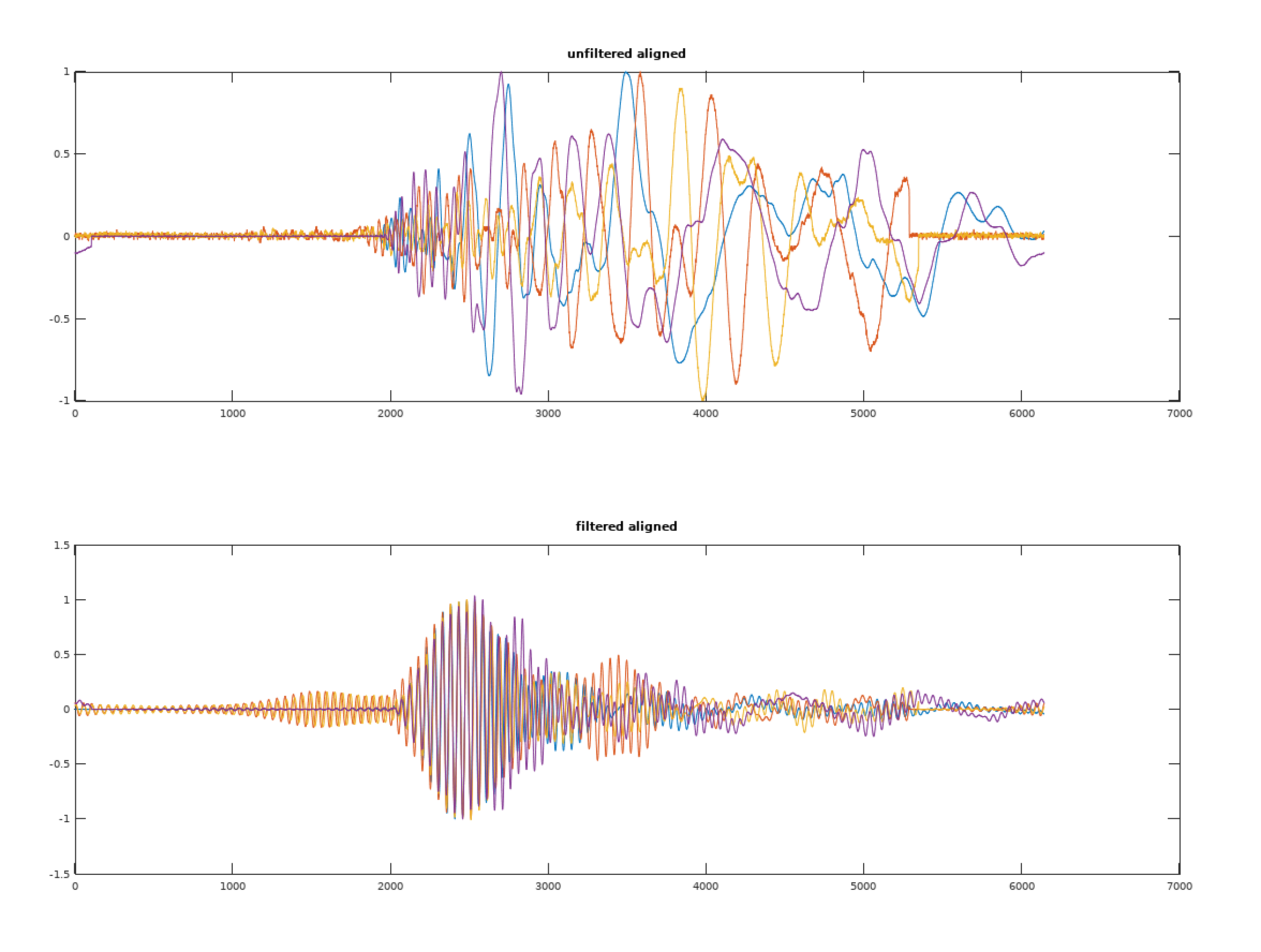
The mind blowing part is when you go back and look at the original signal (normalized, but otherwise unfiltered) and compare.
![]()
When looking at the above, keep in mind that the FIR filter has shifted things on the bottom graph by about 400 samples.
Now to port this into C using the ARM math libraries...
-
Mounting the Piezos
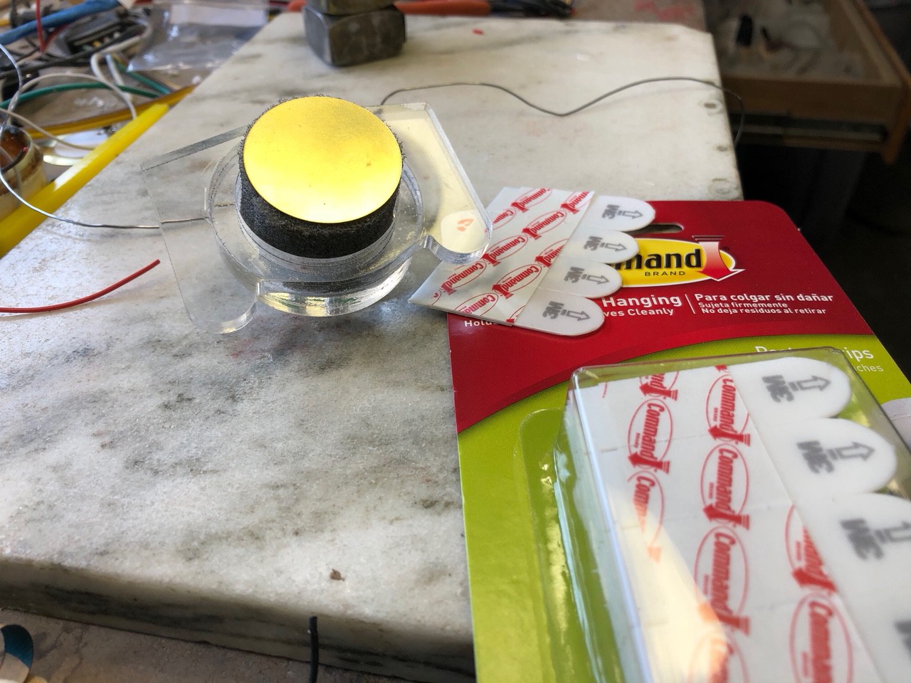
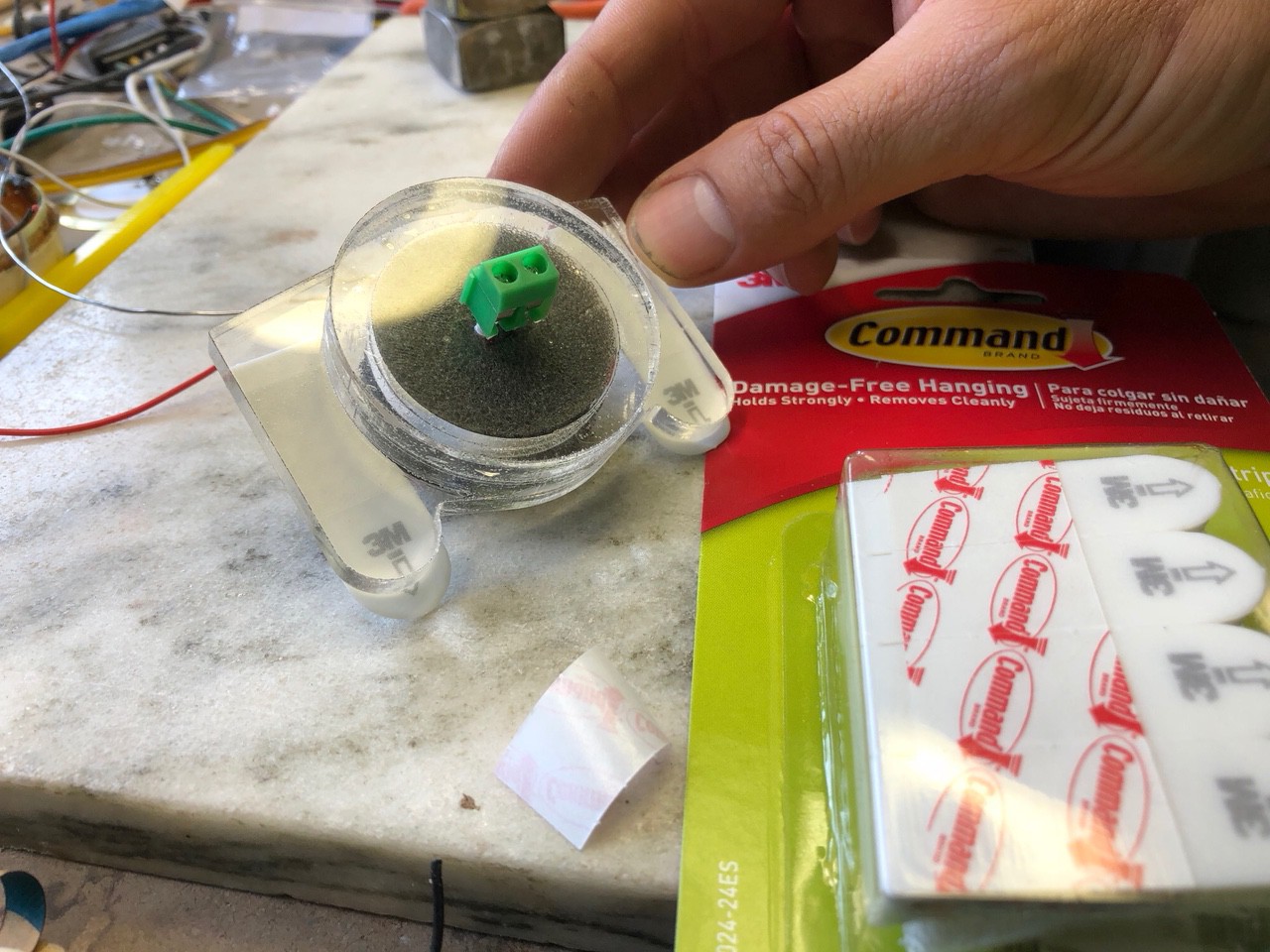
08/24/2018 at 13:59 • 0 commentsThere are all sorts of ways you could attach the piezos but its really important that they be held consistently. Just taping them works ok but the tape slowly gives up a little and that can have big effects on the signal. This is what I have found works the best.
![]()
Its a simple laser cut housing, I used .25" acrylic but anything will work. The housing is 1/2" deep and holds a 1" piece of polyurethane that was also cut on the lase to the right diameter. On the back side I have a simple screw terminal.
![]()
This is held onto the surface with 3M Command removable strips. The setup keeps the piezo firmly to the surface and still allows it to vibrate.
-
Cross (Correlating) the Streams
08/18/2018 at 21:04 • 0 commentsWith a bit of help from GNU Octave and an idea of which frequency bands are interesting, I can now play around with cross correlating the signals.
Here is the cross correlation output (xcorr) showing time offsets from negative on the left to positive on the right.
![]()
The interesting thing here is the positive peak. This indicates the delay where the signals most closely align.
To make things easier, I can make a function to find this delay:
function ret = findDelay(a,b)
  [R,lag] = xcorr(a,b);
  [v,i] = max(R);
  ret = i - length(a);
endfunction
To get an idea of what that looks like when applied back to the signals, I can plot the unaligned and aligned signal by shifting the second by the delay.
![]()
Looks pretty good!
Now theoretically this will work great, but to calculate all of this on the STM32 will be a lot of number crunching. Each channel needs to be filtered, which is currently 6k samples per channel, and a FIR filter of sufficient size needs to be created. Octave has me covered there too, and this article has everything I need to know about designing these filters. It will be an accuracy/CPU time trade-off.
Next I need to cross-correlate the signals, though I don't really need or want the full result, I only need the peak and the delay of the peak. Still, that is a lot of vector dot products to calculate. Maybe I can cheat and check at a lower resolution, find a rough match, then fine tune it.
-
Take It up an Octave
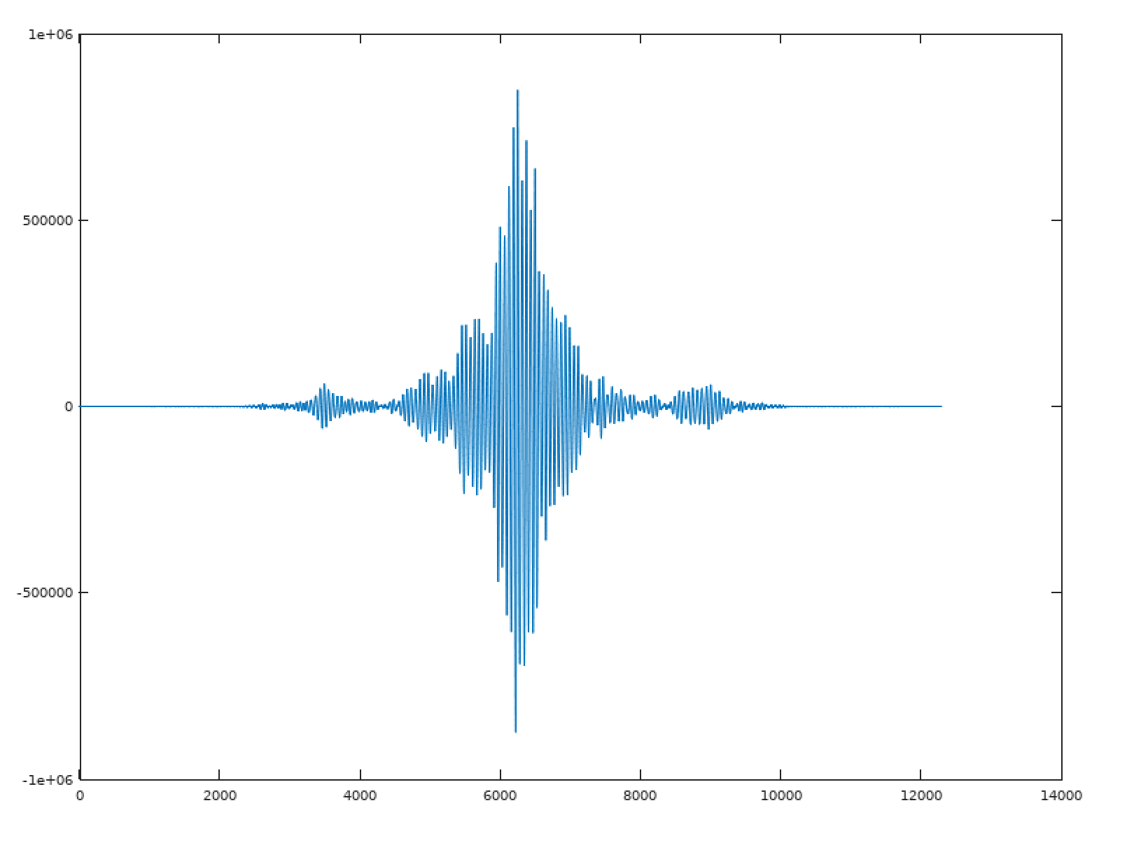
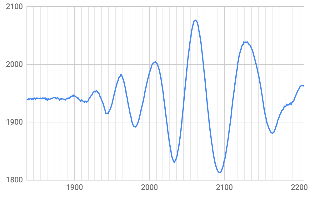
08/07/2018 at 16:33 • 0 commentsWith sensors mounted to an acrylic sheet, I get something like this:
![]()
It looks like there is some noise, and a few frequencies going on in here. This is after a high-pass filter on the analog side around 1.6KHz.
One of the things I'm keeping an eye out for are different kinds of waves. There's transverse waves where the material wobbles up and down, the kind you'd think about with sound. With a sensor attached directly, it's possible to pick up longitudinal or compression waves that travel through the material.
Like earthquakes. The "P wave" travels faster and can give early warning of an incoming quake. If the signal has longitudinal waves, part of the signal will travel faster. Those should also have a higher frequency. Unless they are picked apart, I imagine they will mess with correlation.
So I wanted to pick apart the signals by filtering, but haven't done much digital filtering. After googling a lot, I found some FIR filter designers, but I wanted a way to quickly experiment and get a feel for what these are doing.
Enter GNU Octave.
I found this absolute gem that has pretty much everything I need:
https://www.allaboutcircuits.com/technical-articles/design-of-fir-filters-design-octave-matlab/
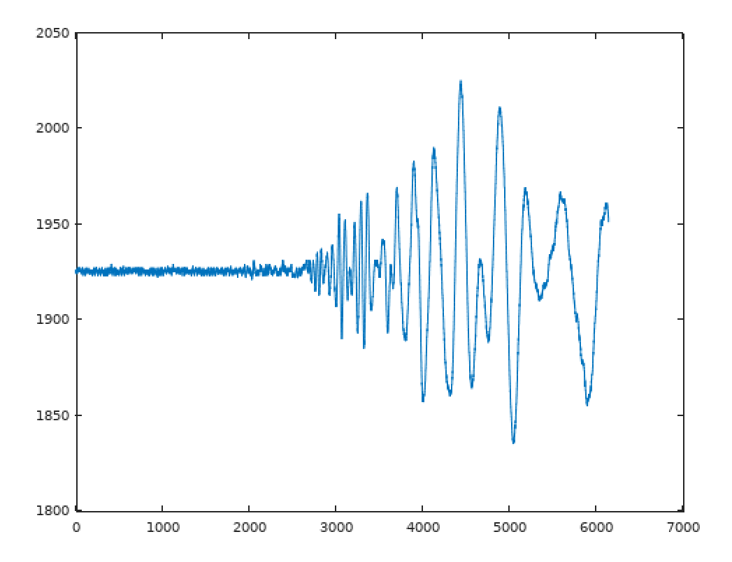
With a bit of fiddling around, I can see different frequencies and pick them apart. This is way better/faster than anything I've done before.
![]()
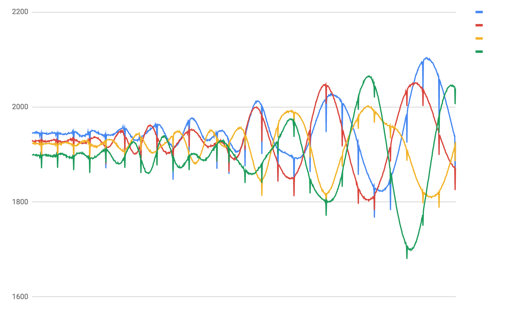
The blue line is the signal through a low pass, and the red line is after a bandpass for higher frequencies but excluding high frequency noise. It looks like there are 2 signals in there, and the higher frequency signal does look like it travels faster than the low frequency signal. Does this mean I found longitudinal/compression waves?
I'll have to see what I get after correlating the signal components. Ch1 and 4 should be about the same, and ch2 and 3 should be about the same as these where intentionally arranged in 2 equidistant pairs from the tap source.
-
Tiny Oops
08/06/2018 at 14:01 • 0 commentsI didn't find any reference schematic for USB in the datasheet or reference manual, so I just kind of wired it up and hoped for the best. D+ to DP D- to DM, seemed logical enough. There's a Cube checkbox for phy, so I figured the chip must have whatever it needs internally.
Plugged it in, and nothing... Not even a blip on the console.
You'll have to forgive my optimism, the only other project I've done with USB directly (instead of through UART to USB) was on one of those "Blue Pill" boards, and it just worked.
So I googled around and found a schematic for it, sure enough...
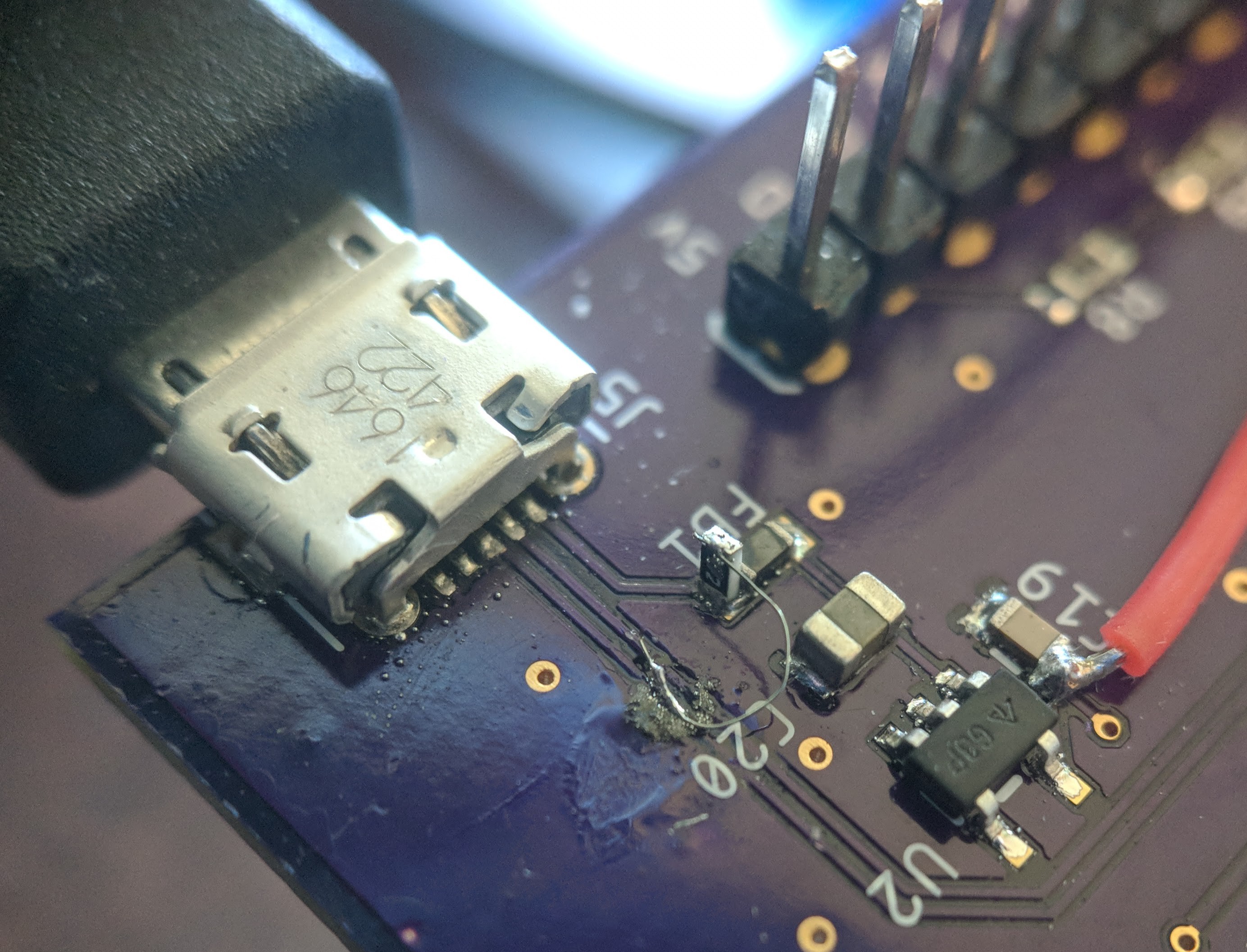
Turns out I need an external pull-up resistor on D+
![]()
-
Thinking about cross correlation...
08/05/2018 at 23:44 • 0 commentsWow, the arm_math CMSIS stuff is really nice. Tons of stuff there, and the source is available, and even optimized to use SIMD instructions when available.
I think I'm going to go with a vector dot product, and slide that down a smaller window based on where I think the opening waveform is. I don't have the memory or need for the full correlation waveform, just peak correlation detection, and I think I can use a smaller window around where the ADC WD tripped, then scan down the other channels looking for peaks in correlation where the start of the waveform matched.
-
Beautiful Data With... Icicles?
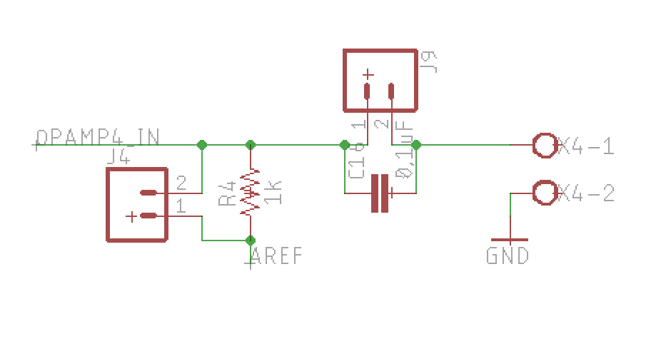
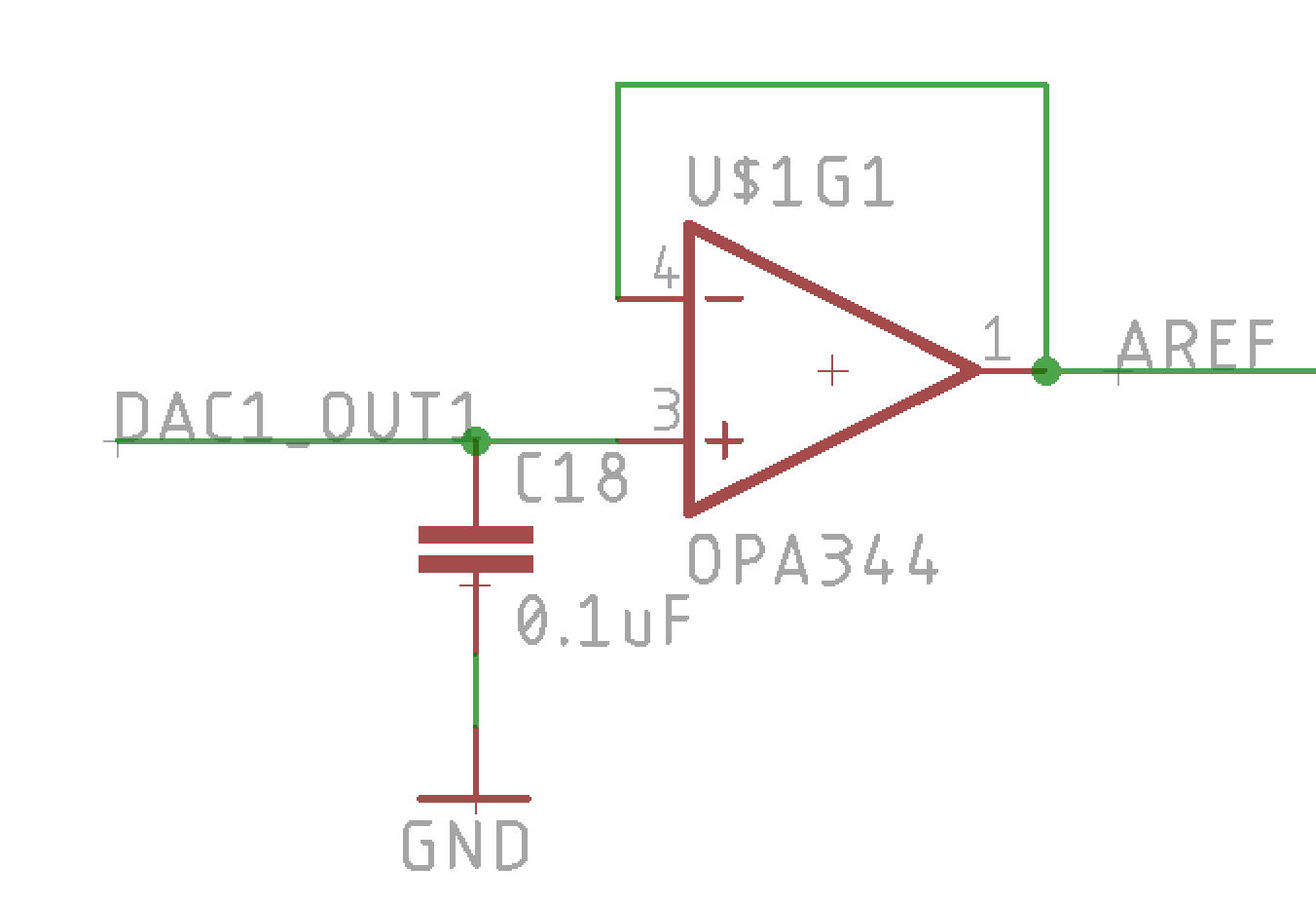
08/05/2018 at 17:06 • 0 commentsThe piezo goes through a very simple high-pass filter into the op amp w/ PGA set to 16x, then on to the ADC.
![]()
(piezo is connected to the terminal on the right)
This should give me about 1.5Khz cutoff to filter out the DC and any bass. I don't yet know exactly what kind of frequencies I'm dealing with yet. What does a 'tap' look like? The connectors (J4, J9) let me probe and experiment with values if necessary.
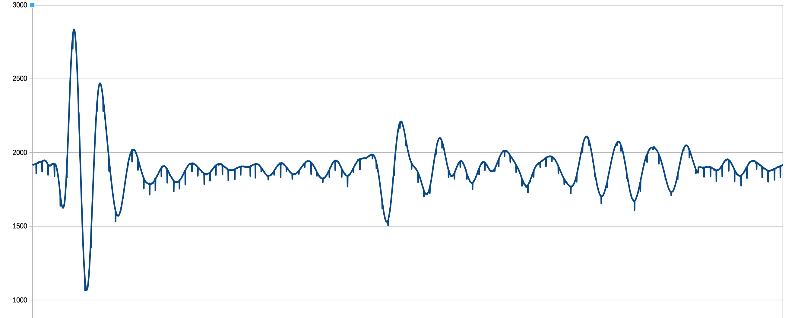
So with everything hooked up, lets see what we get:
![]()
Beautiful! But... WTH are icicles doing in the data? Also my circular buffer math is off, signal starts about 1/16th of the way in and wraps around.
![]()
It's on all channels at the same time!
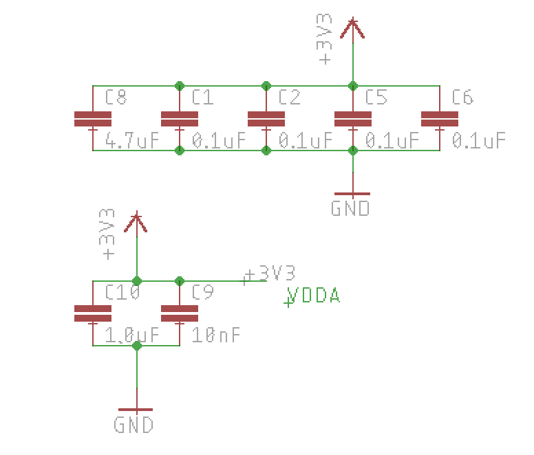
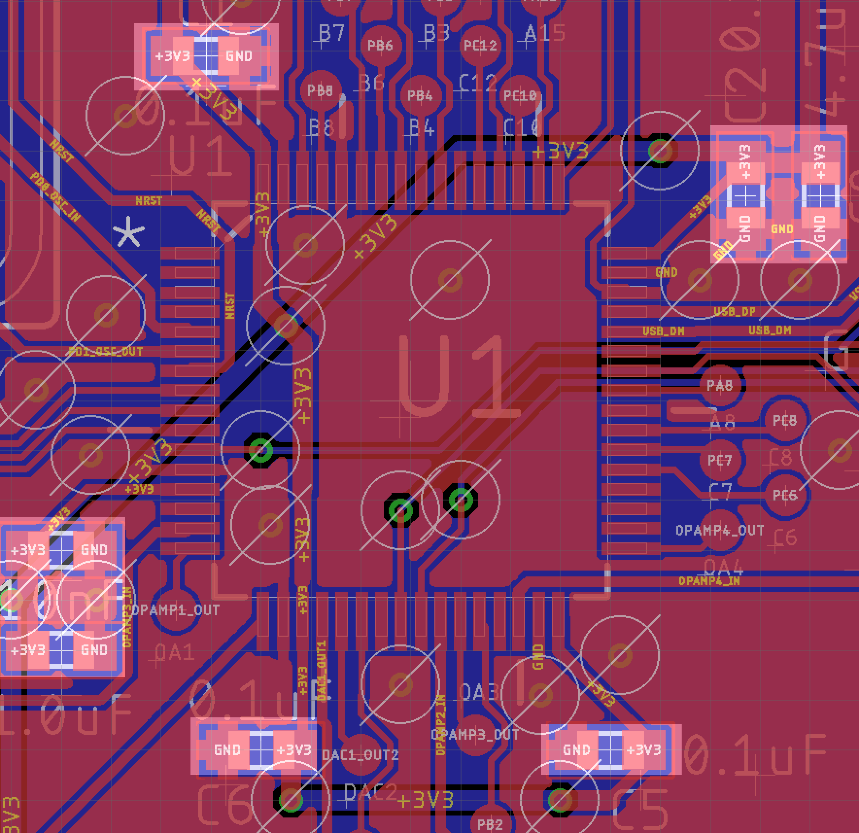
I double checked power supplies. Maybe something on the chip (USB perhaps?) was activating on some interval causing load spikes on the power supply? I thought I added enough decoupling caps by following the datasheet!
![]()
![]()
Maybe some kind of ADC spitback even though it's fed into the op amps? Did I create some kind of resonant circuit with the piezo?
I tried disabling everything else the chip was doing. I tried changing the PGA gain.
Scoped everything (power, piezo inputs, pre op amp, post amp, ref voltages). I didn't find any causes, my poor scope (owon DS7102V) is either blind to the icicles or the probe suppresses them.
Mystery Fix
I experimented a bit. Adding a 10k resistor in series with the piezo fixed the weird icicles, but I don't yet know why.
![]()
Noise is now about 2-3 LSB and some of that might be background audio getting picked up, or stray EMI on the piezo leads. Will have to check that out at some point, but the above looks plenty fine for tap detection and correlation!
Maybe Related
The PGA has a fixed GND reference, so I can't just float 1/2 of 3.3v on the op amp. Instead I use the DAC to output a reference voltage that once multiplied by the PGA is about 1.65v. By changing the DAC and PGA at the same time, I can keep close to ideal range and still have programmable gain control.![]()
So theoretically glitches on the DAC or extra buffer could be the cause, but scoping this didn't show noise.
-
Ode to HAL
08/05/2018 at 16:45 • 0 commentsOh HAL,
We're not a match.
I tried to be your pal
but you make my head scratch.Your code is a puzzle
and the interface is jagged.
While CPU cycles you guzzle
my interrupt is run ragged!But the hardware is elegant,
you time wasting contraption.
I've discovered registers most relevant
now I'm done with this abstractionHello ARM World
ST has made getting in to ARM pretty easy. I had some false starts with NXP, but these STM32 NUCLEO dev boards with ST-Link debuggers and free high quality tools are really nice.
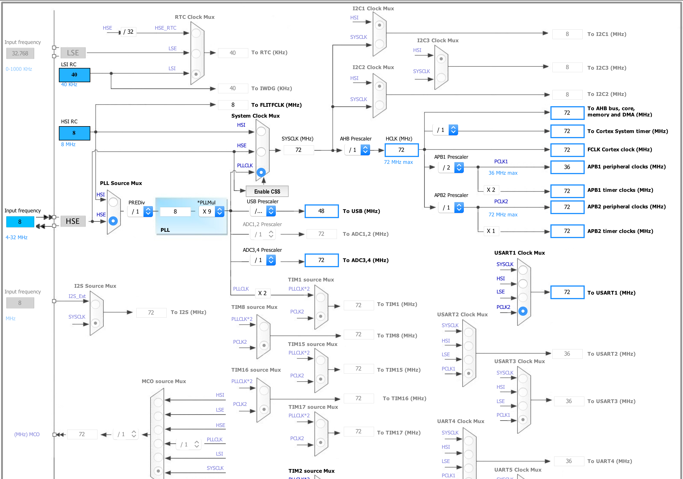
These STM32F303RE are pretty complex chips with a lot going on, a lot of registers and clocks and all kinds of rules. Here's the clock tool in STM32CubeMX, a chip configurator and code generator:
![]()
(it doesn't all fit on my screen)
Using the tool definitely saved a ton of time. It has a lot of sanity checks, and generates code in either HAL (Hardware Abstraction Layer) or LL (Low Level). HAL code has a ton of extra sanity checks and promises portability across different chips should the need arise. LL on the other hand is pretty bare bones and gives light wrapper functions around poking registers.
This can be paired with your favorite IDE, or if you want something that is free and takes less time to set up you can use SW4STM32 which based on Eclipse. I used Eclipse in a previous job quite extensively, so I'm comfortable enough with this setup. Its all backed by the all powerful GCC, and integrates well with the ST-Link debugger via Open OCD. The only trick is that you have to fiddle with the Cube settings and import the generated project in just the right way.
Getting Some Data
So the basic capture architecture is this:
            trigger   +------+ dma   +---------------+
            +-------> | adc1 +------>+  circ buffer  |
            |         +------+       +---------------+
            |         +------+ dma   +---------------+
            +-------> | adc2 +------>+  circ buffer  |
  +------+  |         +------+       +---------------+
  | tim3 +--+         +------+ dma   +---------------+
  +------+  +-------> | adc3 +------>+  circ buffer  |
            |         +------+       +---------------+
            |         +------+ dma   +---------------+
            +-------> | adc4 +------>+  circ buffer  |
                      +--+---+       +---------------+
                         |
                         |adc 1-4 watchdogs
                         +------------------->  captureEvent()
The timer tim3 triggers all 4 ADCs simultaneously, which then use DMA to write into a circular buffer. Meanwhile ADC watchdogs keep an eye on measured ADC values and interrupt when a value is outside of a predefined range.
That all happens without any CPU, its all just wiring peripherals and DMA together until the watchdog triggers.
I want to capture some leading data because I won't know when exactly the signal starts. It is likely going to precede the trigger as a weaker signal. Put another way, I want to stop capturing data into the circular buffers after (BUFFER_SIZE - X) more samples are taken, where X is the amount of leading data to capture.
So I thought, I'll just add an interrupt handler to tim3 and decrement a counter. Tim3 is already triggering for each sample. The CPU runs at 72MHz, and the ADCs can run up to about 5Msps. Initially I'm going for 1Msps. That only leaves about 72 cycles between samples, not enough to really do much, but surely enough to decrement a counter, right?
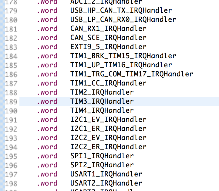
Enter HAL. HAL provides an abstraction layer, but also tons of checks. But it's not written in C++ templates or even a bunch of #ifdefs, its mostly just readable C code. And abstraction. So the interrupt fires, and the interrupt vector looks like this:
![]()
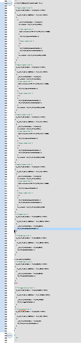
The TIM3_IRQHander is of course provided by the generated HAL code. This calls HAL_TIM_IRQHandler, passing in a pointer to the tim3 hal data structure. But of course HAL_TIM_IRQHandler is generic for any timer, not just tim3, and not even just your flavor of tim3. So it runs through every possible reason any timer could ever interrupt. To be fair its only about 140 lines of code, but here is where my 'user' function gets called from:
![]()
It's buried deep enough that the timer has rolled over a few times before it even executes. Forget decrementing a counter in 72 cycles. If I could implement TIM3_IRQHander directly, it would probably be fine, but the Cube wants HAL to own it. I could inject a bit of 'user' code into it's TIM3_IRQHander and return before HAL, but thats kind of playing dirty, and at that point what is HAL buying me?
So HAL might not be the best fit for every application, and certainly won't work for this. I could switch to LL and probably be OK for 1Msps, but probably not a good approach if sampling is increased near 5Msps.
The good news is that I have heaps of timers available on this chip, so its easy enough to fire up another timer and unburden the CPU from handling anything related to tim3.
TapTDOA
Turn almost any flat surface into a sensor using cheap piezos and time difference of arrival.