As the boards arrived I started the assembly of the first prototype. The power filtering first and then the sensing and the transimpedance sections. There was a serious mistake in the BPW34 Eagle library - dot marking the anode was at the wrong side of the part. Unfortunately a few of the diodes were damaged after I found the cause.
Proper TIA feedback resistance value
Currently I am focused at the TIA stage and the proper signal processing. With a live working detector, I am able to measure the real data and see the simulated circuit in the real conditions. There is a significant dissonance between the simulations and real circuits in this case.
Here are some results I gathered with a few Rf values:
I also conducted tests with the value of 1 Giga Ohm, but no pulses were detectable even with the radioactive source present. The op amp that was used (LTC6268) had a bandwidth of 500MHz, there is also an upgraded version of it with the BPW of 4GHz, I hope to test it soon and see if the optimal working point will shift upwards in favor of greater resistance values. From the data gathered I estimated that the Rf value should be somewhere between 1-10M Ohms. I guess aiming at the 2,2 to 4,7M will provide the pulses of length about 1us with the sufficient amplification and sensitivity - ideal for subsequent processing.
Noise issues
The new detector design is extremely sensitive to noise. The PIN diodes generate a lot of it and additional high voltage sources like energy saving lightbulbs or CRT affect it and distort everything. The simple switching of a soldering station renders a spiking in the signal. The shielding is an absolute necessity unless the circuit is enclosed in a grounded metal case where the measurements will take place. The noise level is about 12mV peak to peak, but still the pulses are distinguishable, which is nice.
I am thinking of a new way to process the signal to prevent the undershoot and eliminate the constant noise level at the early stage by a simple subtractor and ideal rectifier circuits made with op amps. Then an additional stage of two Sallen-Key filters acting as a gaussian shapers and the signal would be ideal for acquisition.
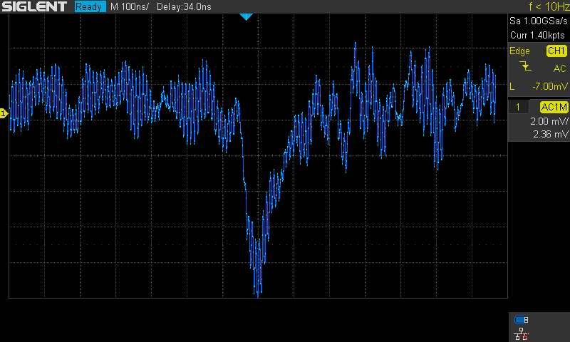
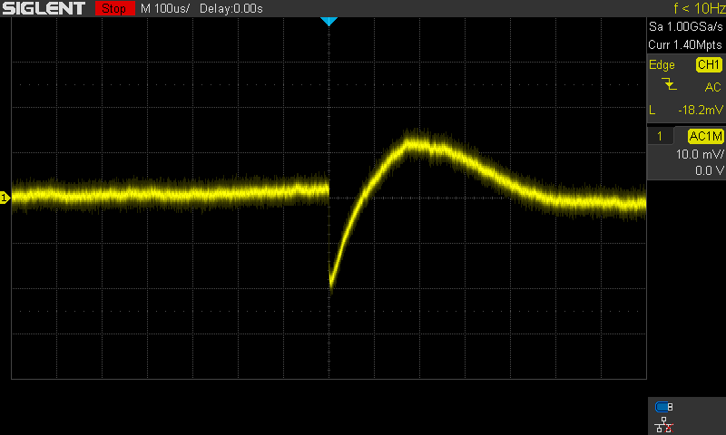
Rf = 100k measurements:
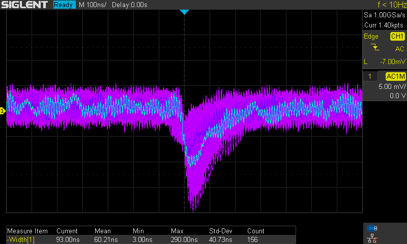
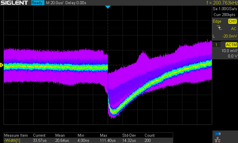
Rf = 1M measurements:
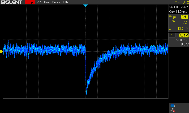
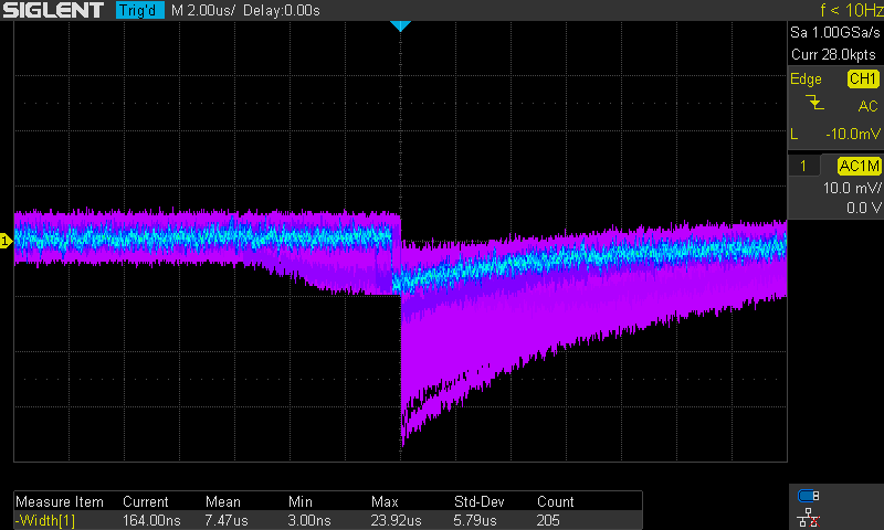
Rf = 10M measurements:
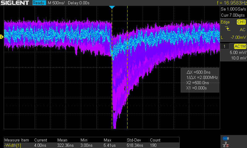
Rf = 100M measurements:
Discussions
Become a Hackaday.io Member
Create an account to leave a comment. Already have an account? Log In.