Close
0%
0%

Z80-MBC2: a 4 ICs homebrew Z80 computer

Homemade 8MHz Z80 SBC, 128kB banked RAM, RTC, SD (HD emulation), Basic and Forth interpreter, CP/M 2.2 and 3, UCSD Pascal, Fuzix and more...

Similar projects worth following
The Z80-MBC2 is an easy to build Z80 SBC (Single Board Computer).It is the "evolution" of the Z80-MBC (https://hackaday.io/project/19000), with a SD as "disk emulator" and with a 128KB banked RAM for CP/M 3 (but it can run CP/M 2.2, QP/M 2.71, UCSD Pascal, Collapse OS and Fuzix too).

It has an optional on board 16x GPIO expander, and uses common cheap add-on modules for the SD and the RTC options. It has an "Arduino heart" using an Atmega32A as EEPROM and "universal" I/O emulator (so a "legacy" EPROM programmer is not needed).

It is a complete development "ecosystem", and using the iLoad boot mode it is possible cross-compile, load and execute on the target an Assembler or C program (using the SDCC compiler) with a single command (like in the Arduino IDE).

* NOTE TO THE READER *: Due to a text size limitation of the Hackaday. io site a few chapters have been moved to "Log files". In this case you have just to click on the link of the chapter's title to open a new tab and read it.
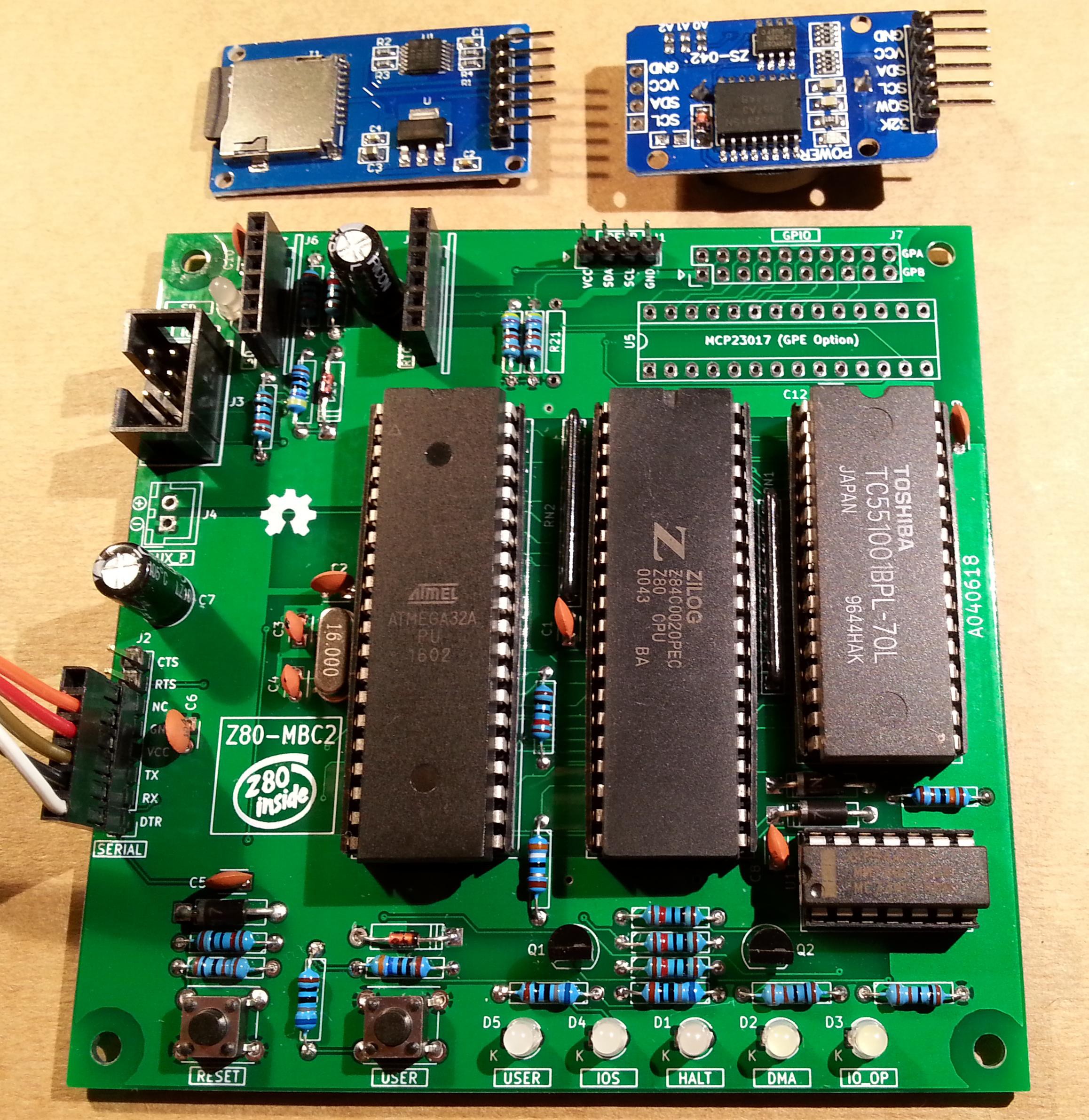
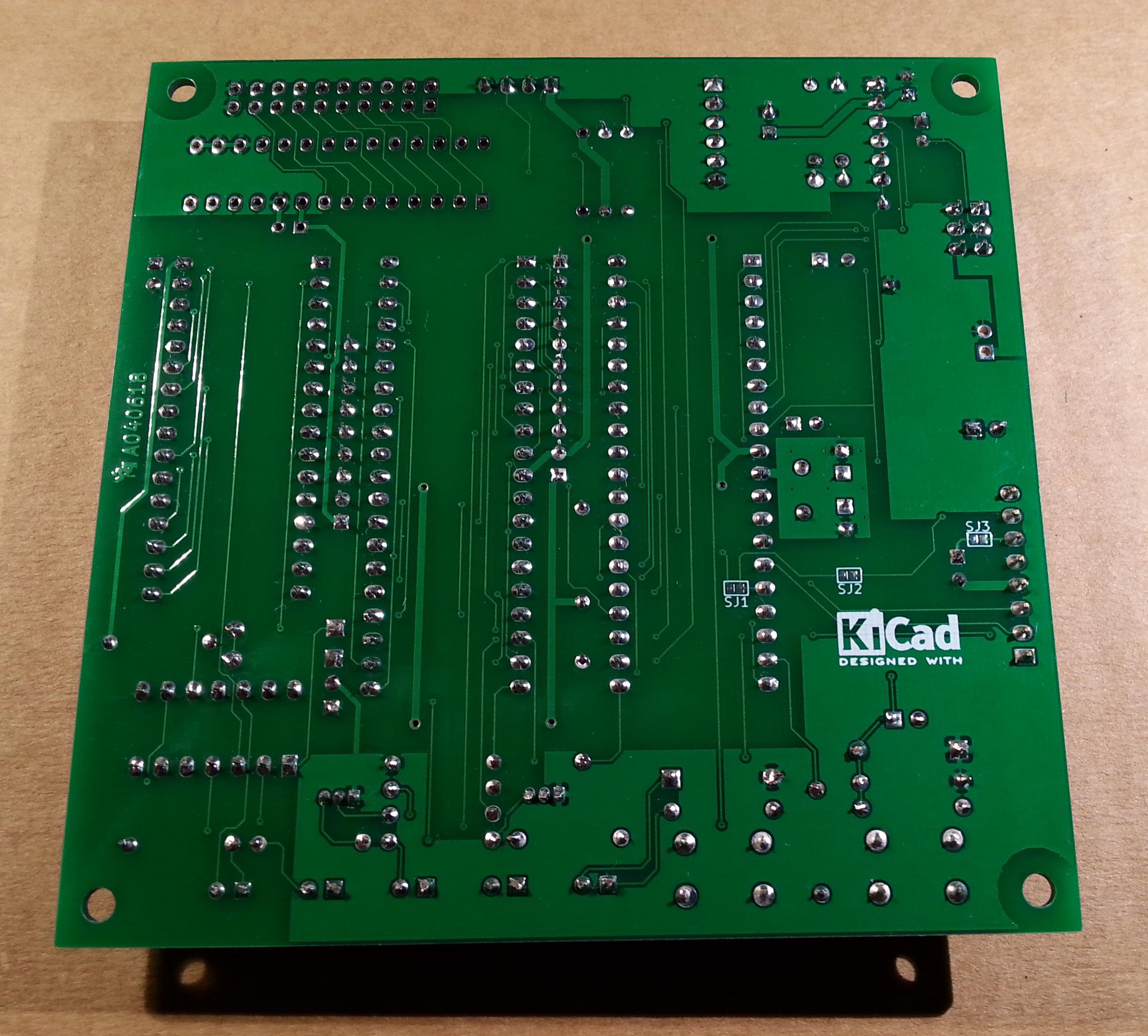
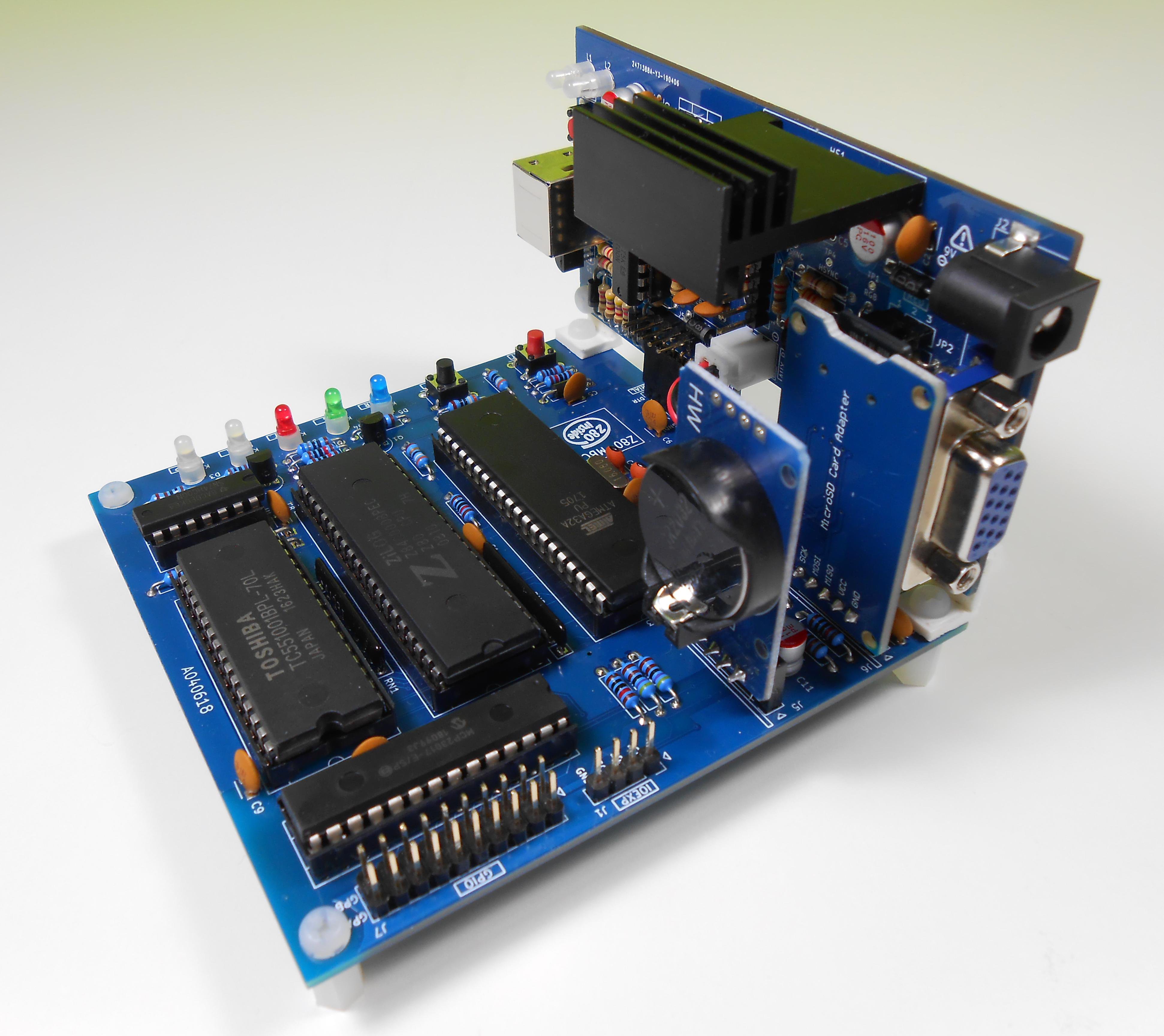
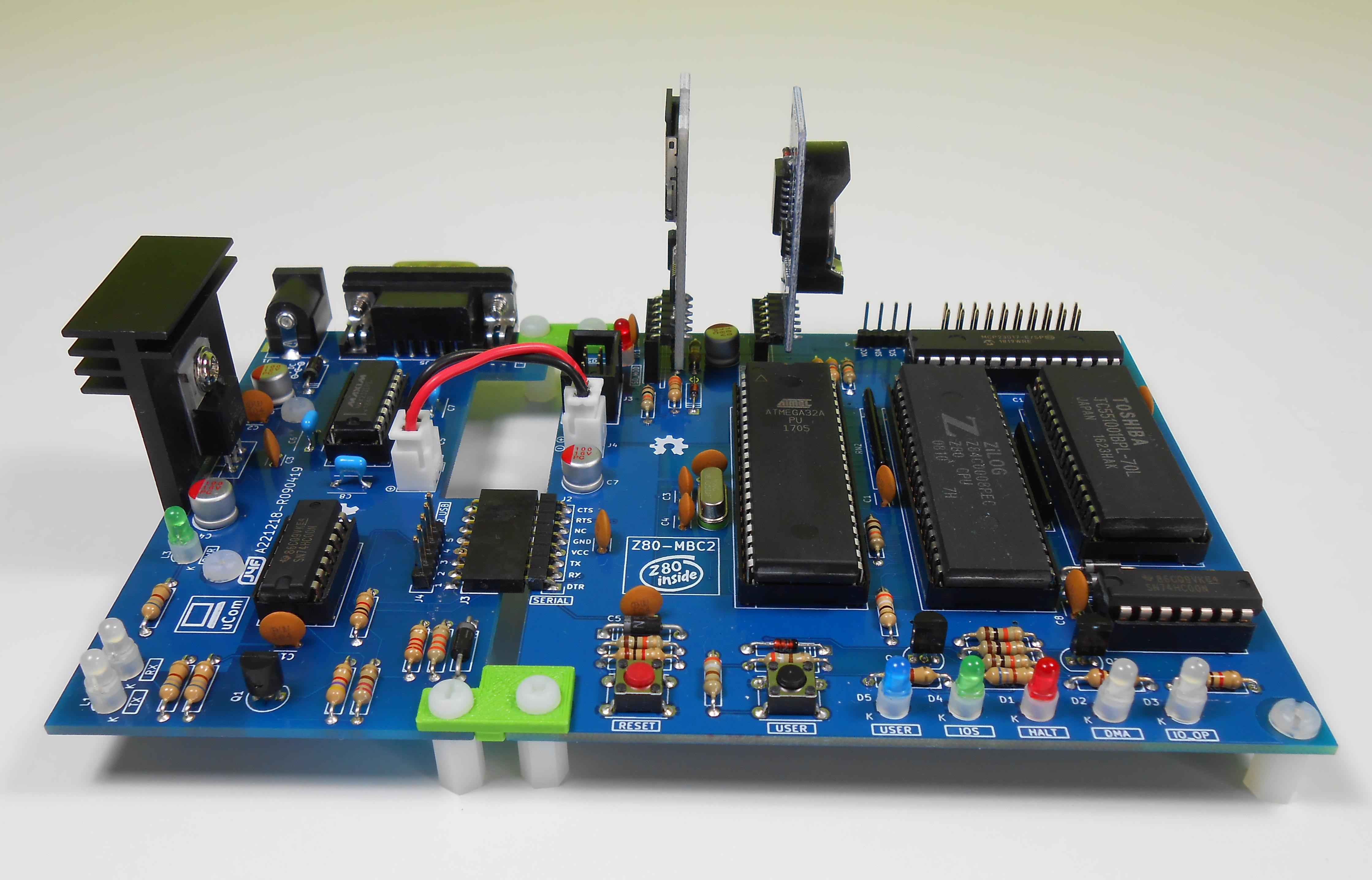

* * HARDWARE OVERVIEW * *

The needed ICs for the "base system" are:

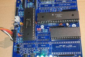
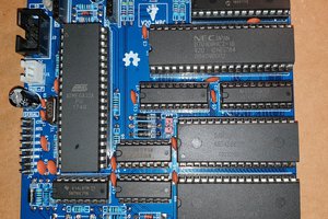
  • Z80 CPU CMOS (Z84C00) 8Mhz or greater
  • Atmega32A
  • TC551001-70 (128kB RAM)
  • 74HC00

If you want the 16x GPIO expansion (GPE option) add a MCP23017 too.

The schematic and the BOM are attached in the Files section. The MCU Atmega32A is used as universal I/O subsystem, as Eeprom, and as reset and 4/8MHz clock generator for the Z80 CPU.
Inside the Atmega32A it is flashed an Arduino bootloader taken from here, and it is possible to use the Board Manager of the Arduino IDE to "import" it.

Flash the Arduino bootloader at first (with the method you prefer), next you can upload the IOS "sketch" (the I/O Subsystem that interacts with the Z80 bus and "virtualizes" the EEPROM and all the peripherals seen by the Z80 CPU) using Arduino IDE.

You can use the on board ICSP port J3 (also called ISP port) to write the bootloader, but remember to disconnect any other connector when using it. Also both SD and RTC modules (if present) must be removed from the board when the ICSP port is in use.

As clock source for the Z80 CPU it is used the 16MHz Atmega32A oscillator, so the "external 16MHZ osc." bootloader variant must be chosen when flashing the bootloader from the Arduino IDE!.

The 74HC00 is used as RS flipflop to stop the Z80 CPU during I/O operation, giving the needed time to the Atmega32A to interact with the Z80 bus, and as part of the MMU.

Note that only the CMOS version of the Z80 CPU can be used here. This because only CMOS version, under given condition that are respected in this schematic, has logical levels compatibles with Atmega32A and 74HC00.


NOTES ABOUT THE COMPONENTS

You should use a  Z80 CMOS speed grade of at least 8MHz for full speed, but setting the clock speed at 4MHz you can use a 4MHz Z80 CMOS version too (or you can try to overclock it at 8MHz...). The 74HC00 can be substituted with a 74HCT00 if you already have one. The RAM chip TC551001-70 can be substituted with any suitable 128kB SRAM).

Please note that the USER led  * must * be blue or white (or pink... I've some pink leds that seems to have a Vf like blue one. May be I'll do a board with them...) just to be sure that V(forward) is >= 2.7V (otherwise the USER key may not work as expected).

The J4 connector (AUX_P) is used as auxiliary power connector when an add-on board (uCom or uTerm) is connected.

The three solder jumpers (SJ1-3) on the bottom side are not currently supported and must  be left opened (as stated in the schematic).


THE GPE OPTION (GPIO CONNECTOR)

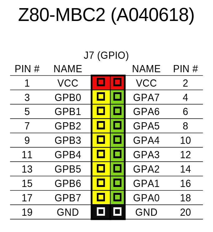
It is possible to choose to populate on the PCB a GPIO port expander (U5) to add 16 bidirectional GPIO pins. The GPE option (see the schematic) can be used with the SPP Adapter board (see the paragraph: SPP (STANDARD PARALLEL PORT) ADAPTER BOARD).

The pinout of the GPIO (J7) connector is:

THE SERIAL PORT

The  SERIAL port (J2, see schematic) can be connected with a TTL-RS232 adapter, or with a serial-USB adapter.
I've used a serial-USB adapter that acts also as power source for the Z80-MBC, and has the DTR signal for the "autoreset" driven from the Arduino IDE. For a terminal that has a serial TTL port no adapter is needed.

Of course to upload a "sketch" from Arduino IDE you need to use a serial-USB adapter connected to the SERIAL port.

Note that the RTS and CTS pins of the SERIAL port are not currently supported and must be left not connected (as the NC pin!).

The 3V3 pin of the serial-USB adapter must be left disconnected  (if present).

You should use those Serial-USB adapters that have the DTR pin on the connector. It is suggested to have also the CTS/RTS signals available for future upgrades.

Please note that all the pin...

Read more »

Z80-MBC2 User Manual - D081023-R280424.pdf

Z80-MBC2 User Manual

Adobe Portable Document Format - 11.66 MB - 04/28/2024 at 15:52

Preview

SD-S220718-R290823-v2.zip

The content of the microSD needed to run CP/M 2.2, CP/M 3.0, QP/M 2.71, UCSD Pascal, Collapse OS and Fuzix with IOS S220718-R290823 (More info in the Changelog.txt file inside)

Zip Archive - 5.81 MB - 10/06/2023 at 10:40

Download

S220718-R290823_IOS-Z80-MBC2.zip

The sketch for the IOS (with the needed libraries). Unzip into a folder and open the .ino file (with Arduino IDE). IOS must be uploaded into the Atmega32A flash. Adds support for Fuzix OS and the SPP Adapter board (more info in the changelog inside the .ino file).

Zip Archive - 43.75 kB - 09/24/2023 at 11:59

Download

S220718-R290823_IOS-Z80-MBC2.ino.with_bootloader_atmega32_16000000L.hex

The sketch for the IOS in executable format (.HEX) with the bootloader. This executable file is intended for use with a programmer as the Atmel Ice or AVRISPmkII or others (Fuse bits: High Byte 0xD6, Low Byte 0xAF, Lock Byte 0xCF)

x-hex - 59.90 kB - 09/24/2023 at 12:04

Download

SPP Adapter board - A240721-R270921.zip

All the documentation needed to build the SSP (Standard Parallel Port) Adapter board (A240721-R270921) including schematic, PCB assembling guide, Gerber files for PCB production. PCB is 55mm x 60mm 2-layers.

Zip Archive - 747.10 kB - 09/24/2023 at 15:10

Download

View all 13 files

  • 1 × See the file "A040618 BOM v2.ods" in the FILES section.

  • * * ​USING THE TASM CROSS ASSEMBLER * *

    Just4Fun10/09/2023 at 14:07 0 comments

    * * USING THE TASM CROSS ASSEMBLER * *

    The TASM cross assembler (Windows CLI application) can be used for various CPU. It can be downloaded from here. The on-line manual is here.

    Using the TASM cross assembler it is possible setup a toolchain to program the Z80-MBC2, doing all the development on a PC and uploading the code with the serial port and then executing it on the target Z80-MBC2 with iLoad.

    After the download of the TASM zip file, unzip it into your working directory (it is the folder where your assembler source files are stored) and to assemble an user source give the command:

    tasm -s -h -c -g0 -80  <Your_source.asm> out.hex

    It will be created the out.hex file (Intel-hex formatted executable file).

    Now you can upload and execute out.hex using the iLoad boot mode of the Z80-MBC2.

    Remember that iLoad will take the first address of the Intel-Hex stream as the starting address of the program, and after the loading will jump to it.

    At this point you can follow the same steps to create an automated toolchain described in the paragraph "SDCC: SETTING UP AN AUTOMATED TOOLCHAIN (WINDOWS)".


    TASM: USING AUTOBOOT

    If you want create a binary file to use with the Autoboot boot mode you can generate it with the command:

    tasm -s -h -c -g3 -80   <Your_source.asm> out.bin

    It will be created a flat binary file out.bin. Then rename out.bin as autoboot.bin and copy it into the root of the SD used by the Z80-MBC2.

  • * * ​USING THE SDCC CROSS COMPILER * *

    Just4Fun10/05/2023 at 13:27 0 comments

    * * USING THE SDCC CROSS COMPILER * *

    Using the SDCC (Small Device C Compiler) cross-compiler it is possible setup a toolchain to program the Z80-MBC2 with the C language, doing all the development on a PC and uploading the code with the serial port and then executing it on the target Z80-MBC2 with iLoad

    SDCC can be found here: https://sdcc.sourceforge.net/.

    After installing it, SDCC needs to be in some way instructed about how to deal with the specific HW of the Z80-MBC2.

    For this reason in the SD image, inside the \SDCC folder, there are two support files: S190818-R011023_crt0.s and S290923_Z80-MBC2.c.

    All the steps needed to configure the toolchain are explained below (we will assume a Windows operating system here, but the steps are similar for Linux):


    STEP 1:

    Copy the two support files S190818-R011023_crt0.s and S290923_Z80-MBC2.c from the SD image (\SDCC folder) to your working directory (it is the folder where your C source files are stored) and compile the first file with the command (from your working directory):

    sdasz80 -plosgff -o S190818-R011023_crt0.s

    It will be created the S190818-R011023_crt0.rel file.


    STEP 2:

    Now it's time to compile the second support file (S290923_Z80-MBC2.c). Here things are a little more complex because this file can be compiled in two different ways which differ depending on whether interrupts are enabled or not.

    The  need to have interrupts enabled or not depends on whether your user program uses them or not.

    To enable the interrupts support compile with the command (from your working directory):

    sdcc -c -mz80 -DZ80MBC2IRQ S290923_Z80-MBC2.c

    Instead to disable the interrupts support compile with (from your working directory):

    sdcc -c -mz80 S290923_Z80-MBC2.c

    It will be created the S290923_Z80-MBC2.rel file.


    STEP 3:

    iLoad uses the first address as starting address for the execution, so the executable file (Intel-Hex formatted) must be in ascending address order. This is not guaranteed by SDCC, so you need to use the srec_cat utility to sort the file. You can download this utility from here: https://srecord.sourceforge.net/  and then you have to copy the srec_cat.exe file into your working directory.


    All done!

    To compile your source file the command is (from your working directory):

    sdcc -mz80 --no-std-crt0 S190818-R011023_crt0.rel <your_source.c> S290923_Z80-MBC2.rel -o temp.hex

    It will be created the temp.hex file (Intel-hex formatted executable file).

    Now to sort the file give the command (from your working directory):

    srec_cat -disable-sequence-warnings temp.hex -Intel -o out.hex -Intel

    This will create the sorted file ready to be loaded with iLoad: out.hex.

    Now you can upload and execute out.hex using the iLoad boot mode of the Z80-MBC2.


    SDCC: SETTING UP AN AUTOMATED TOOLCHAIN (WINDOWS)

    To create an automated toolchain you need another "ingredient", a terminal emulator supporting scripts. Here we will use Tera Term. You can download Tera Term from here: https://ttssh2.osdn.jp/index.html.en.

    After installing Tera Term, from the SD image inside the \SDCC folder, copy into the working directory the following batch files: SDC.BAT and L.BAT.

    Before using the L.BAT batch file you have to adapt two parameters according with the configuration of your PC. 

    Go at line 18 and verify the path where Tera Term (ttermpro.exe) is installed, and at line 19 the number of the COM port used to connect the Z80-MBC2 to your PC.

    You need also to copy the Tera Term script LoadZ80.ttl from the /SDCC folder (inside the SD image) to the directory where Tera Term (ttermpro.exe) is installed, and adapt the parameter at line 15 with the complete path of your working directory in your system.

    Now to compile your_source.c file give the command (from your working directory):

    SDC your_source.c

    and to upload and execute it on the Z80-MBC2 (from your working directory):

    L

    Remember to close the Tera Term window...

    Read more »

View all 2 project logs

Enjoy this project?

Share

Discussions

O.E wrote 02/16/2020 at 17:47 point

Hi,

After i setud circuit i connected to computer using FTDI programmer leds blinking correctly but terminal is not  open in computer when  pressing buttons.

  Are you sure? yes | no

Just4Fun wrote 02/17/2020 at 11:18 point

Hi,

have you set the sw terminal at 115200 8N1 (No HW handshaking)...? Are you sure to have connected RX/TX correctly...? An other "source" of common problems is a wrong fuse setting when flashing the bootloader first time...

  Are you sure? yes | no

wojtek.p wrote 01/13/2020 at 12:20 point

Hi,

Does anyone have 3D models (step format) for Z80-MBC2, uCom and UTerm? I want to design a 3D printing case and it would be helpful. If anyone has, please send to wojtek.p@onet.pl

Thanks

Wojtek

  Are you sure? yes | no

wenij wrote 01/12/2020 at 09:55 point

hi,

have any one knows how to build the Z80-MBC2_figforth130.asm source code?  which tools set to build?


thanks.

wenij

  Are you sure? yes | no

WestfW wrote 01/16/2020 at 23:41 point

For the MBC1, I used the TASM3.2 cross assembler for DOS/Win, which you can apparently download from: https://www.ticalc.org/archives/files/fileinfo/250/25051.html

  Are you sure? yes | no

Tony Nicholson wrote 10/12/2019 at 11:32 point

This is a fantastic little board.  I'm now starting to tinker with things a bit and I'll be attempting to combine the CP/M 3 bios modules with Simeon Cran's ZPR3 replacement BDOS routines (obtainable from the Tesseract RCPM+ archives - volume 93 at http://www.classiccmp.org/cpmarchives/cpm/mirrors/www.triton.vg/TesseractRCPM+Catalog.html#vol93 ).

Before doing this I thought I'd attempt to reconstruct the supplied CPM3-128.SYS system from sources and I'm not having much success - in particular with all the choices when running GENCPM.  Would you be able to share the build procedure and corresponding GENCPM.DAT file?  Thanks.

  Are you sure? yes | no

HerveGZ wrote 07/12/2019 at 17:08 point

Dear All

Thanks again for this wonderfull Z80 board. And sorry to start a question as beginner, but

Is there a link to a startup guide global of this board? (something detailled explain)

Even I use it yet, I  have some problems to understand the I2C (protocol I know):
In examples there are out 1,opcode and out 1, value in general is so. But as I want to add my own I2C systems (from Grove or Seeed firms) I do not understand the relation between those out 0,xxx and out 1,yyy and the I2C address (Each item has a unique one ) of my own components I2C.

Can someone thanks  to enligh me on I2C how to mbasic can i drive any component I2C added please?

Sincerely

Hervé

  Are you sure? yes | no

Just4Fun wrote 07/12/2019 at 17:31 point

Hi, opcodes are used to access to the virtual I/O devices. Read the comments in the .ino sketch about the virtual I/O engine to understand how they work (there are large comment parts in the code that are a sort of manual).

About  accessing your I2C device, this requires  changes in the FW. Some users in the FB users group have already done this to access an I2C LCD module.

You have to create new opcodes to access new I2C HW.

  Are you sure? yes | no

freefuel wrote 07/12/2019 at 07:46 point

I think the RTS and CTS labels are reversed on Serial header J2 on page 2 of 3 on the circuit diagram. the pins they are connected to on the AVR chip do not match. 

  Are you sure? yes | no

Just4Fun wrote 07/12/2019 at 17:34 point

RTS and CTS are connected to two GPIO. There is nothing to "match". More they are not currently supported.

  Are you sure? yes | no

freefuel wrote 07/12/2019 at 22:12 point

OK the documentation is confusing in it's current state.

  Are you sure? yes | no

freefuel wrote 07/12/2019 at 06:22 point

could PD2 pin 16 on the AVR be used to drive a latch for PC0, PC1 respectively pins 22 and 23 for the I2C interface to drive two additional SRAM address bits? I ask as I noted there is a pin compatible SRAM on digikey with a stated 4 Megabit/512K Byte capacity. (My other thought was to borrow a GPIO pin from the IO expander if you were only interested in warm booting between the banks.)   

  Are you sure? yes | no

Just4Fun wrote 07/12/2019 at 17:36 point

The bank switching HW is tailored to a 128KB SRAM.

  Are you sure? yes | no

freefuel wrote 07/12/2019 at 22:13 point

what harm would there be in wiring the currently unused GPIO to A17?

  Are you sure? yes | no

Adrian Wallaschek wrote 06/26/2019 at 00:50 point

Hi again, I have been hypnotizing the sheet for more than an hour now. Really? For the bootstrap the AVR serves as RAM? I guess the ce2 is used to shut up the SRAM, from then on, the AVR serves the reads. The bootstrap code works unrelated of the Z80s current PC: LD HL,something, then for each byte LD (HL),byte ; inc HL. There is no loop needed, just pump the bytes by repeating the last two. This will even work if the bootstrap target and the current PC overlap. Guys, I assume I guessed right +- some detail. This is really nice! From there on everything is IO and not memory. So my remaining question is: how do you terminate the data-provisioning on an IN-command? The WAIT triggers, the AVR puts the byte on the databus and resets the flipflop, the Z80 will read, but what makes the AVR then pull the D-bus on the AVR high? Is that hardcoded like several nop commands on the AVR and then pull high? assuming a nop is a single cycle and the relations of the frequencies are known. That easy?

Why am I asking: I try to do something like this with an Arduino-Mega, just with a bit more luxury. I thought to make the IN-command completely async, so the Arduino feeds a databus latch that is reset by a flipflop in reaction to IORQ going 1. But this turns the shield into a TTL-graveyard. If the nop-timing proves to be stable, it would easy my schema a lot.

For those interested: the Arduino Mega with its XMEM interface would offer real DMA. All I need now is a reliable IO-protocol.

Any confirmation to my guesses (I am too lazy to try to locate the right place in the code, to be honest ;-) shame on me) would be welcome.

  Are you sure? yes | no

Just4Fun wrote 07/12/2019 at 17:45 point

The Z80-AVR interaction schema uses a Wait-Bus_Hold sequence and was designed to be time-independent.

  Are you sure? yes | no

Adrian Wallaschek wrote 06/25/2019 at 23:22 point

I feel like a rookie. I do not understand the world anymore. First I was so stupid to look into the MBC schema instead of the MBC2. (Thanks to the one who pointed me to the right direction!) Now I believe I have the right schema, but I have no clue how this could work.

Why? For the MBC2 the only direct address-line connected to the AVR is A0. Now in order to boot the sketch would have to copy the bootstrap into the RAM before resetting the Z80, right? The MBC had more lines connected and that I understood, but with one address-line? Does the RAM have a boot-functionality so content can be clocked in just based on A0?  

So how does the bootstrap get into the RAM? Or is the sketch A040618 missing some connections? Honestly I believe my brain does. I do understand the wait logic and the GPIO is pretty straightforward, but how the bootstrap would work or how the bankswitching works escapes me ... completely. I feel old and tired.

Is there a kind of documentation with an explanation how these parts work? Or could anybody hint me where to find the related code?

Thanks in advance.

  Are you sure? yes | no

WestfW wrote 07/19/2019 at 07:57 point

The way that IO worked on the V1 board is that accesses to IO space would trigger the flipflop that would put the Z80 into "wait" state, essentially halting it.  Then the AVR would figure out what was going on, put stuff on or take stuff off of the bus, and un-flip the flipflop, allowing the Z80 instruction to continue.  Essentially, a really SLOW memory access, with the stuff that normally happens in memory or IO hardware implemented in AVR firmware instead.   I haven't looked at the V2 at all (I ad assumed it worked the same, until your message), but there's no reason that the same scheme couldn't work for Z80 memory accesses as well.  The V1 seems simpler to me - it's easier (?) to make the RAM access be full-speed, but it takes more pins.

  Are you sure? yes | no

Jim Bailey wrote 06/21/2019 at 07:02 point

Is it possible to build this system with a z80 rated for and running at 20mhz?

  Are you sure? yes | no

Just4Fun wrote 06/22/2019 at 17:25 point

The Z80 clock is generated by the Atmega32 and can't be greater than the half of the Atmega clock.

  Are you sure? yes | no

freefuel wrote 07/12/2019 at 06:06 point

so you could do 10MHz if you installed a 20MHz crystal on the AVR?

  Are you sure? yes | no

psmart wrote 06/18/2019 at 22:26 point

Hi,

Please ignore below, the fuses were set incorrectly, CKSEL3:0 were set as 0001!!

  Are you sure? yes | no

psmart wrote 06/18/2019 at 21:48 point

Hi,

Firstly, excellent project Just4Fun, a hark back to hard but fun computer times, nice professional work, thank-you.

Unfortunately Im having issues, I took to building two boards and both exhibit an identical issue so I was wondering if you have come across it. They are both programmed with the HEX file on your file list.

Basically, the IOS light blinks very slowly (every 2 seconds) and there is serial output (either after a plain reset or User+Reset) but not to a baud rate minicom can handle. The SD LED also flashes around the same time serial output occurs. Probing with a scope I noticed that the Crystal wasn't oscillating, I removed the crystal and caps and I still get exactly the same behaviour, it powers up, IOS light blinks slowly and serial output occurs but at a non-standard baud rate. There is also no activity on the Z80 side (ie. reset, D0-D7 are all idle).

First guess I would think the ATMEGA is using an internal oscillator ignoring the external crystal but without delving into the Sketch used to build the HEX file I can't be sure.

The only part Ive deviated from vs the schematic is a 1K resistor for R19 (should be 1K2) as I didn't have any in my parts box otherwise all is per the schematic.

Hence have you any ideas? Is there an issue with the HEX sketch?

Many thanks in advance for any help you can provide.

  Are you sure? yes | no

Jim Bailey wrote 06/16/2019 at 04:43 point

Built one and it worked on the first attempt.  I really love the flexible boot loader, whereby you can load and switch between OS's quickly.  Its fun to get to play with CP/M after all these years.

  Are you sure? yes | no

Linker3000 wrote 05/18/2019 at 20:58 point

Hi @Just4Fun,

Turbo pascal  compiled programs - even a 'Hello world' - exit to a CP/M warm boot. Is this expected as I don't experience this on other boards (RC2014 and a Grant Searle build).

Thanks

  Are you sure? yes | no

Just4Fun wrote 05/19/2019 at 08:56 point

I think this is normal. What type of test have you done?  It is on CP/M 2.2 or 3?
 Could you add more details?

  Are you sure? yes | no

Linker3000 wrote 05/19/2019 at 10:05 point

Hi,


Yes, this is on 2.2 with the following program (compiled to a .com):


  program helloworld;

  begin
    writeln ('Hello world');
  end.

I'm now wondering whether all systems do a CP/M warm start after running it, but only the MBC2 prints a message about it?

  Are you sure? yes | no

Just4Fun wrote 05/19/2019 at 15:35 point

The message on CP/M 2.2 warm boot is my own implementation...

  Are you sure? yes | no

WestfW wrote 07/18/2019 at 01:19 point

IIRC, a "WARM Boot" is how nearly ALL CP/M applications end.  Applications are competing with CP/M itself for RAM (usually <48k in a system), so when you load a program it overwrites the RAM that CP/M was using for the CLI and etc (everything except the code for the "services" that it provides to applications.)  When you exit the application, it has to re-load the CP/M command interpreter and such, which is what they call "warm boot."

  Are you sure? yes | no

Paolo Amoroso wrote 06/24/2022 at 16:42 point

This usually happens when a program terminates by jumping to the CP/M warm boot routine. Can you check the Assembly generated by Turbo Pascal?

  Are you sure? yes | no

Linker3000 wrote 05/17/2019 at 22:28 point

Hi Everyone, I've just updated my Z80 board port/LED writer utility so that it works with the GPIO ports on the Z80-MBC2 (if you've fitted the MCP23017 chip). You'll find the source code and a compiled (.com) version at the link below - upload to the Z80-MBC2 using XMODEM. Check out porter.pas and porter .com at https://github.com/linker3000/Z80-Board. If you do hook LEDs up to the ports, don't forget the current limiting resistors!

  Are you sure? yes | no

Koset *️⃣ wrote 05/05/2019 at 14:19 point

Q: I booted for the first time (yay) and chose BASIC. What's the procedure to exit back to the boot menu? "system", "exit", "bye" yield a syntax error.

I used the ICSP method to burn the boot loader.
Thanks!

  Are you sure? yes | no

Just4Fun wrote 05/05/2019 at 15:36 point

To return to the system boot menu you need to push down both the User and Reset keys, then release only the Reset key holding the User key down, and when the menu appears (or the User led turns off) release the User key (see also the paragraph

HOW ENTER IN THE "SELECT BOOT MODE OR SYSTEM PARAMETERS" MENU:"

in the Description)

  Are you sure? yes | no

Koset *️⃣ wrote 05/05/2019 at 15:38 point

Thanks very much!

  Are you sure? yes | no

jonas.o.gustavsson wrote 05/03/2019 at 11:06 point

Just built my first Z80-MBC2! Actually it is my first "homebuilt" computer.. I found a couple of Z80 CPUs inside some roadside junk a couple of years back. This is really a great project, my hats off to its creator and everyone that has contributed!

  Are you sure? yes | no

makegeneve wrote 04/17/2019 at 18:06 point

I just assembled my kit from Mc John https://shop.mcjohn.it/en/diy-kit/22-32-kit-z80-mbc2.html.  Worked first time.  Excellent work.  Thank you everyone!  Now I'm battling cpm tools on MacOS Mojave to try to transfer a few things across.  It feels very early 80s. :-)

  Are you sure? yes | no

Frank N. Stein wrote 04/04/2019 at 19:29 point

Hi,

your "LADDER" is really nice! - I found only V1.10 on the web and have problems to configure it. :-(

Where did you get your V1.30? - and how did you configure it??? Did you defined "Digital VT100" manually?

  Are you sure? yes | no

Just4Fun wrote 04/05/2019 at 10:44 point

Here: http://web1.foxhollow.ca/Foxhollow-cpm.zip

Ladder 1.30 wortks "out the box"...

  Are you sure? yes | no

Frank N. Stein wrote 04/05/2019 at 19:36 point

Thanks for your link! - It is really called "ladder" in this ZIP-file? I can't find it... :-(

  Are you sure? yes | no

villaromba wrote 04/06/2019 at 15:16 point

Ladder, along with many other games is in the packages folder ( games.pkg). You need to use the instructions at https://web1.foxhollow.ca/cpm/ if you haven't used depkg before.

  Are you sure? yes | no

Just4Fun wrote 04/08/2019 at 09:26 point

Exactly... :)

  Are you sure? yes | no

Frank N. Stein wrote 04/10/2019 at 17:27 point

Thanks! I didn't know DEPKG yet...

Is there actually a way to open these packages under Windows to look inside?

  Are you sure? yes | no

villaromba wrote 04/10/2019 at 20:35 point

Not so sure you can under windows but it's not difficult in CP/M :-

Although you can use xmodem to transfer a single file to your CPM machine, it is
a time consuming task to transfer software collections with large numbers of files.

Step 1: Using the "Binary to CPM Package" utility, you can combine many files to a single file called a package.  (games already packaged)

Step 2: Use xmodem to transfer the package & depkg.com into CPM.

Step 3: Use depkg.com to extract the original files.

Example:  depkg games.pkg

  Are you sure? yes | no

Frank N. Stein wrote 04/14/2019 at 16:33 point

@villaromba: Thanks for your detailed explanation - that works!

  Are you sure? yes | no

Frank N. Stein wrote 03/12/2019 at 08:24 point

@Fabio:

Many, many thanks for the X-Modem implementation!!! Can you maybe post the matching Arduino HEX file? - that would surely be easier than rebuilding the whole Arduino IDE...

THANK YOU VERY, VERY MUCH FOR YOUR EFFORT!!!

  Are you sure? yes | no

Just4Fun wrote 03/12/2019 at 14:21 point

Ok, I'll upload the .hex executable (version with the bootloader included) this evening...

  Are you sure? yes | no

Just4Fun wrote 03/12/2019 at 16:50 point

Done!

  Are you sure? yes | no

Frank N. Stein wrote 03/12/2019 at 20:19 point

FANTASTIC! Xmodem works like a charm! Really super! This is a great enhancement!!! Thank you very much!

UPDATE:

I have problems with "GPELED.BAS", "RTC.BAS" and "USERLED.BAS" - it seems that all programs don't work anymore?!?

  Are you sure? yes | no

Just4Fun wrote 03/13/2019 at 18:05 point

Just tested now... They works now only with QP/M 2.71 that I left untouched and uses the old serial I/O mode.... hmmm...
I think to have an idea of the problem, and it should affect only "slow" interpreted programs (not the compiled one...)...
Further analysis is required...

  Are you sure? yes | no

Just4Fun wrote 03/14/2019 at 07:35 point

I think to have found the cause... now thinking to a possible solution...

  Are you sure? yes | no

Frank N. Stein wrote 03/25/2019 at 12:10 point

Your "SD-S220718-R260119-v2.zip" works very well (I tested Xmodem, "RTC.BAS", "USERLED.BAS" and my own programs on CP/M 3 - it seems that everything is now working properly)! THANKS!

  Are you sure? yes | no

Similar Projects

Does this project spark your interest?

Become a member to follow this project and never miss any updates