Arduino Enigma
-
Wrote Rachel's OS to access buttons and lights
12/30/2018 at 05:47 • 0 commentsWrote Rachel's OS, a set of functions that provides the status of the buttons, whether they are pushed or not right now as well as debounced status. The lights can also be controlled by setting a value in an array.
A sound composer app was also written:
-synth parameters for all 4 buttons get loaded from eeprom on startup
-press a blue button to play the synth note saved for that button
-press left yellow button to move the selection blue light to the next blue button
-the sequence is off,1,2,3,4,off
-press middle yellow button to play the synth note selected by the pots
-press the right yellow button or the selected blue button to save the synth parameters for that blue button and write those values to eepromThe SoundComposer sketch can be downloaded here:
The voice board PCB can be ordered here:
-
10/08/18 - Performance videos and next steps
10/08/2018 at 04:53 • 0 commentsHere are the videos of music produced by Rachel.
Rachel's Nightmare running a 4 step sequencer:
Rachel's Nightmare running an interactive Sound Composer:
A simple five button head unit, can serve as a master to the voice cards:
Polyphony test:
Next Steps:
Testing serial communication using the Software Serial library to pass messages from the five button head end to the worker units. Each worker unit has an unit ID address stored in EEPROM and only responds to messages addressed to it.
![]()
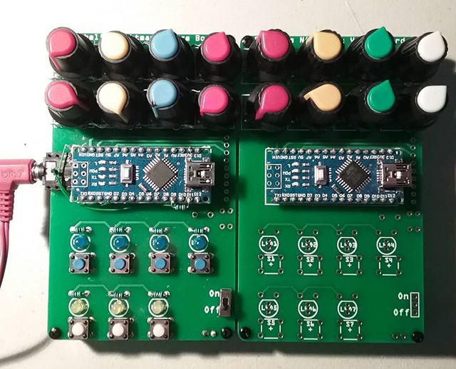
Voice Cards side by side:
The voice cards are meant to be networked by connecting them using the vertical header on the right side of the cards. This header exposes the communication, power, ground and audio pins. A back plane will supply power to each card and contain the audio mixer.
By having bi-directional communication between the master and worker cards, the master can receive the status on the potentiometers on the worker cards.
![]()
Instagram posts:
-
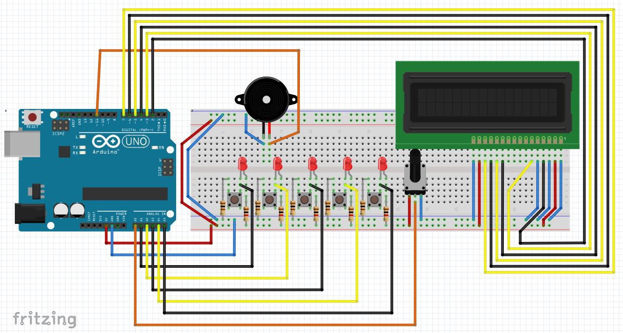
10/01/18 - A five button piano
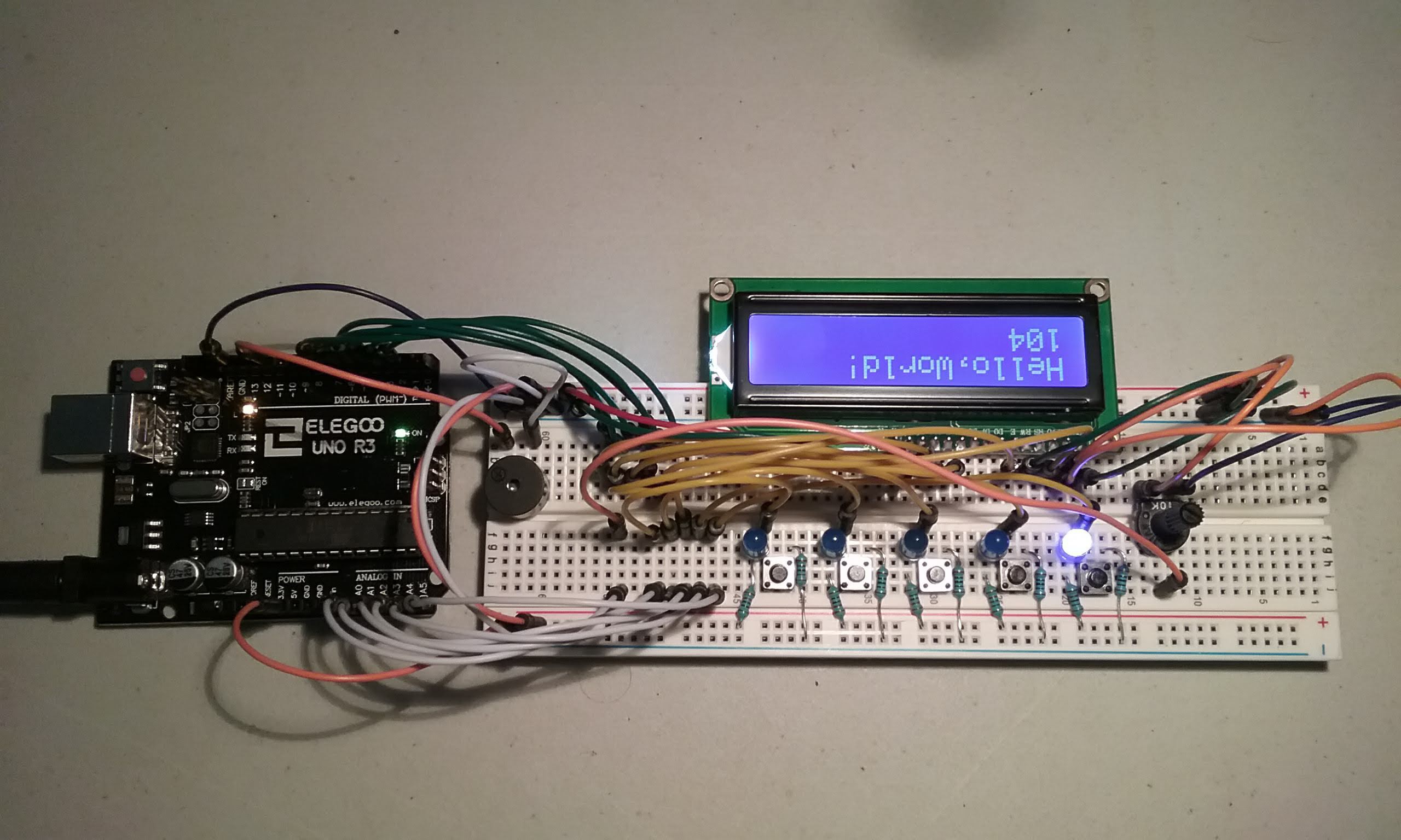
10/01/2018 at 04:34 • 0 commentsHere is a five button piano made with the DZL synth software and Rachel's keyboard / led circuit. Audio is produced via the onboard piezo speaker.
![]()
A picture of the completed circuit:
![]()
And a demo:
Instagram posts:
-
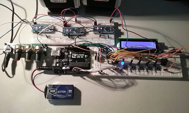
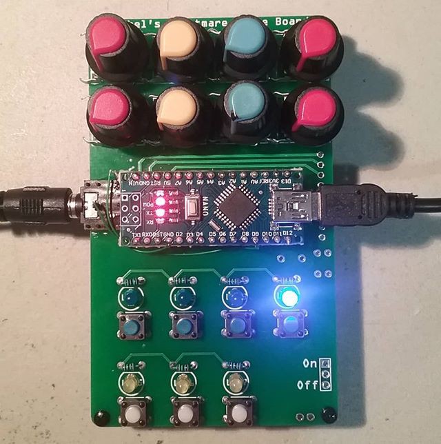
09/09/18 - A working mobile operator
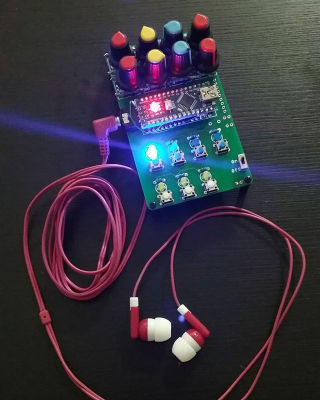
09/09/2018 at 18:53 • 0 commentsA four step sequencer / synth software was written and a battery pack glued to the underside of the voice board. This makes it a mobile operator version. With a set of headphones, you can jam on the go.
![]()
Instagram posts:
-
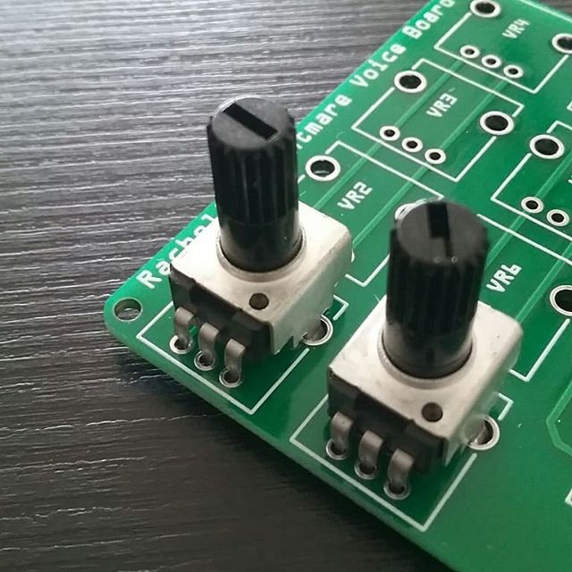
09/01/18 - The proper RV09 potentiometers arrive
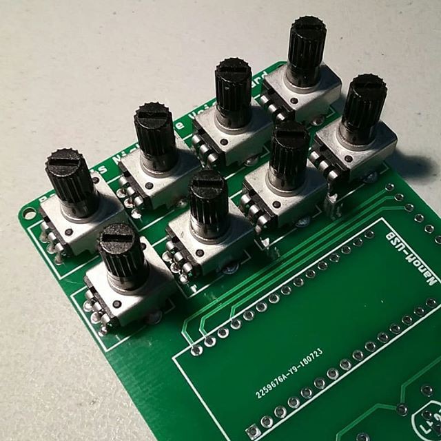
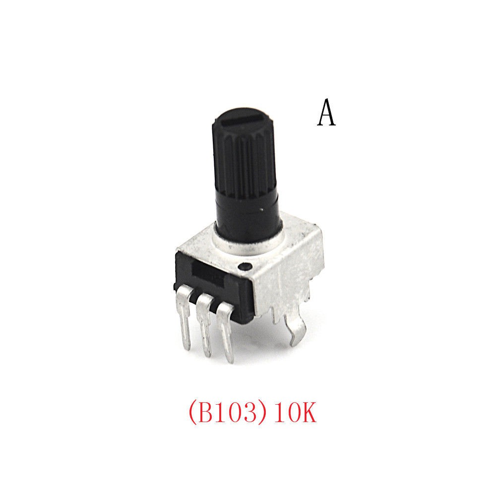
09/09/2018 at 18:49 • 0 commentsThe proper pots arrive. The next board revision will definitely need more space between them.
These are 10K and will be used in a second voice board.
Some 100K pots also came in the mail and will be used soldered in a voice board that will function as an 8 channel passive mixer.
One board, multiple uses.
![]()
![]()
Instagram post:
-
08/21/18 - Automatic selection of active audio-out pin
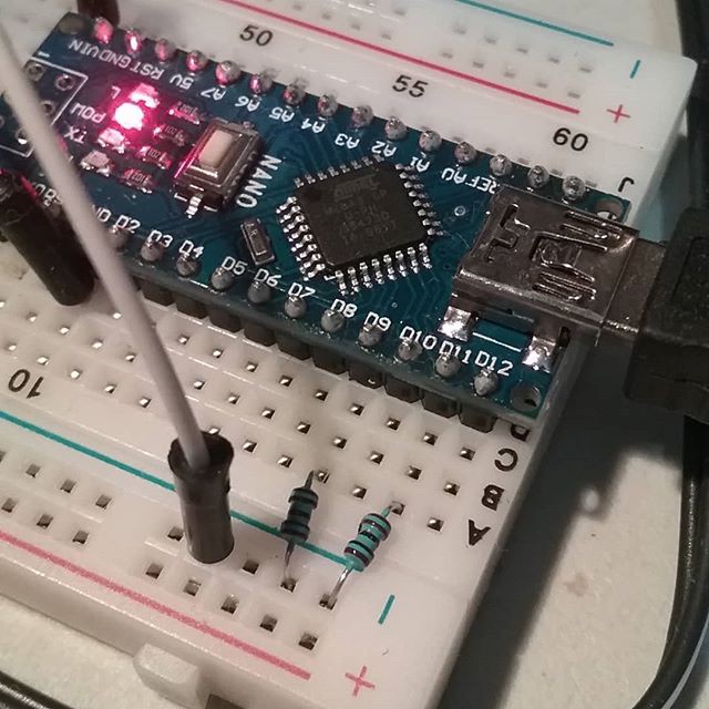
09/09/2018 at 18:42 • 0 commentsMozzi puts out audio on pin 9. Dzlonline synth software uses pin 11. The following circuit automatically connects the pin producing the audio to the audio out through a resistor. The other resistor will be connected to a pin configured as an input and should have no effect in the audio.
With this little mod, either synthesizer software can be loaded and it will work without modifying or reconfiguring the board.
![]()
A simpler modification for the existing board. The output impedance will not be the same for both synthesizers, but it will work as a quick and dirty hack.
![]()
Instagram posts:
-
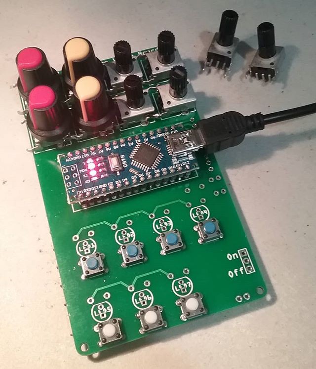
08/19/18 - Received Potentiometers, First Unit Assembled
08/19/2018 at 05:03 • 0 commentsAfReceived an order of RV09 potentiometers, but the style I got is not the right one. After bending the legs, they can be soldered. It is not the right component, but this hack will have to do for now.
![]()
I found these two pots in an older Seeed Studio Arduino Starter Kit. At a minimum this lets us verify that the footprint is right.
![]()
And a picture of the Assembled Unit:
![]()
Here are the wishlist items for the next board:
1) The second row of pots needs to move a litte bit down.
2) The pots could be spaced wider horizontally.
3) Add a 4 pin header so pins 9 and 11 can be connected with a jumper to Audio out. This will allow different synth software to run on the same hardware.
4) Find a spot for the Audio Out header.
5) Relocate the power switch
6) Decide on a communication protocol. If SPI, reclaim one I/O pin to use as a push button in order to have 8 pots and 8 push buttons.
And here is a video of the hardware being tested:
Audio out is working. Next is to figure how to map the pots to the correct values expected by the Mozzi synth software.
And the instagram posts for this log:
https://www.instagram.com/p/BmmUbAhAWRS/
https://www.instagram.com/p/BmoD6BKAWL8/
-
08/05/18 - Schematics for Passive Mixer
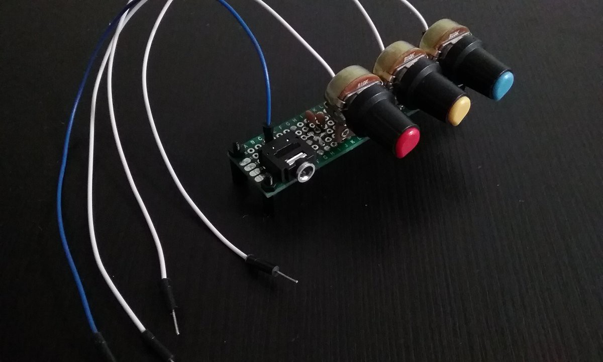
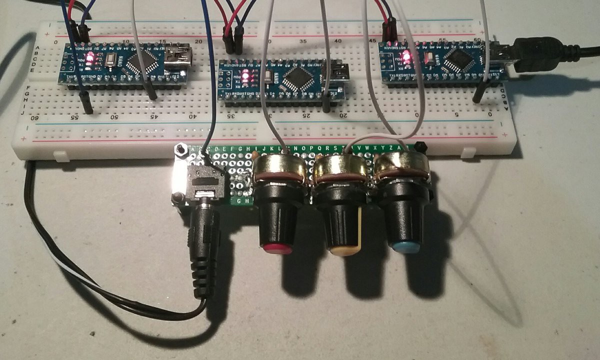
08/10/2018 at 22:01 • 0 commentsHere is a picture of the assembled mixer:
![]()
The white wires are signal inputs for each different channel. The blue wire goes to the common
ground. This mixer assumes all channels share a common ground.
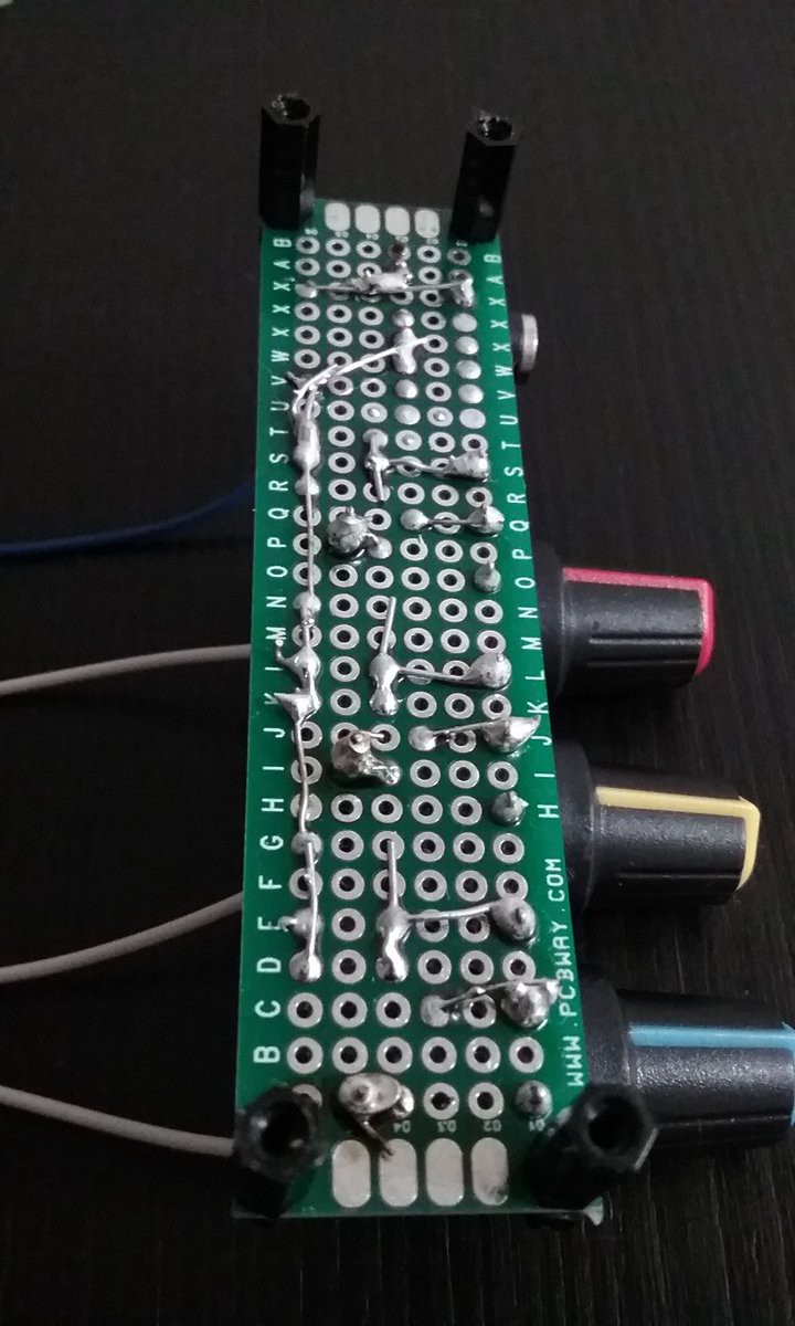
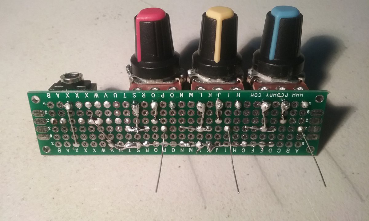
![]()
![]()
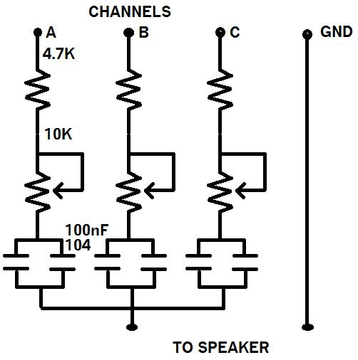
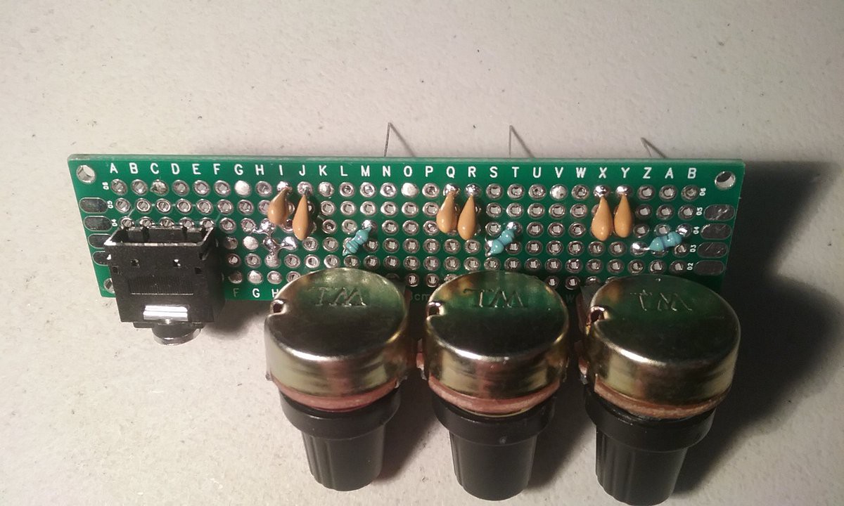
The component values were chosen based on what I had lying around.
![]()
Currently waiting for the a shipment of the following potentiometers in order to populate the voice cards.
-
07/30/18 - Passive Mixer Completed
07/31/2018 at 03:48 • 0 comments -
07/29/18 - Building A 3 Channel Passive Mixer Dead-Bug Style
07/31/2018 at 03:46 • 0 comments
Rachel's Nightmare, a distributed polyphonic synth
Uses multiple Arduino Nano and a passive mixer to generate multiple voices simultaneously.