Hey people!
I got big news: I won a competition with University of Rome Sapienza, which I attended, and now I'm bringing this project to Maker Faire in Rome from October 3rd to 5th!
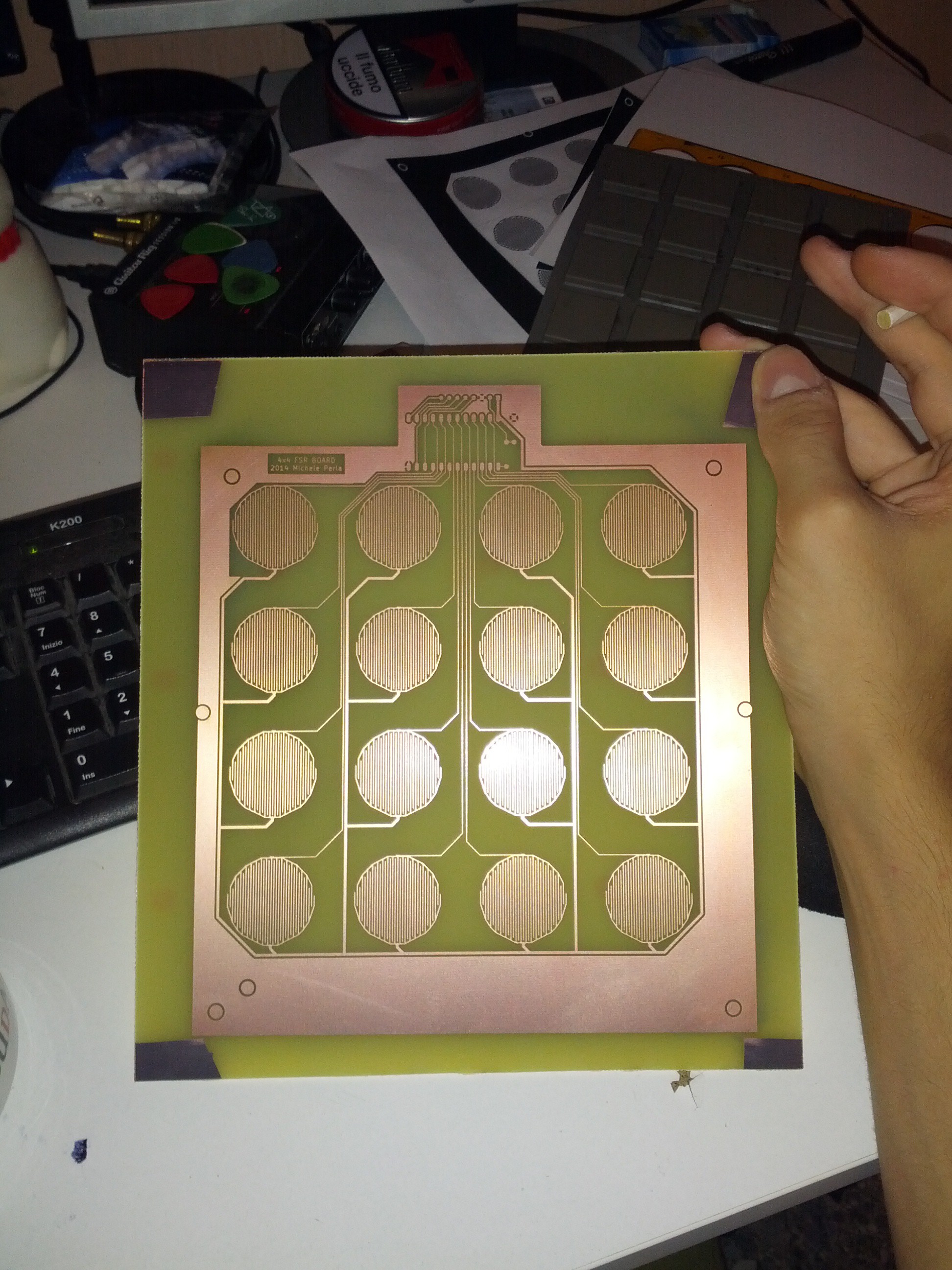
That's why I'm actively working on Revision 2 of this project! In fact, I just printed the first working PCB of the FSR matrix! See it here below in all of its glory and copperness!

Unfortunately I'm encountering issues with drilling holes in PCBs, mainly because it's my first time handling a Dremel and secondly because I do not have a drill press (which I will buy in the next days), therefore I managed to make two holes in a test PCB and breaking 2 drill bits, the 1mm and 0.6 mm ones, so I couldn't drill this one and I could not test it :(
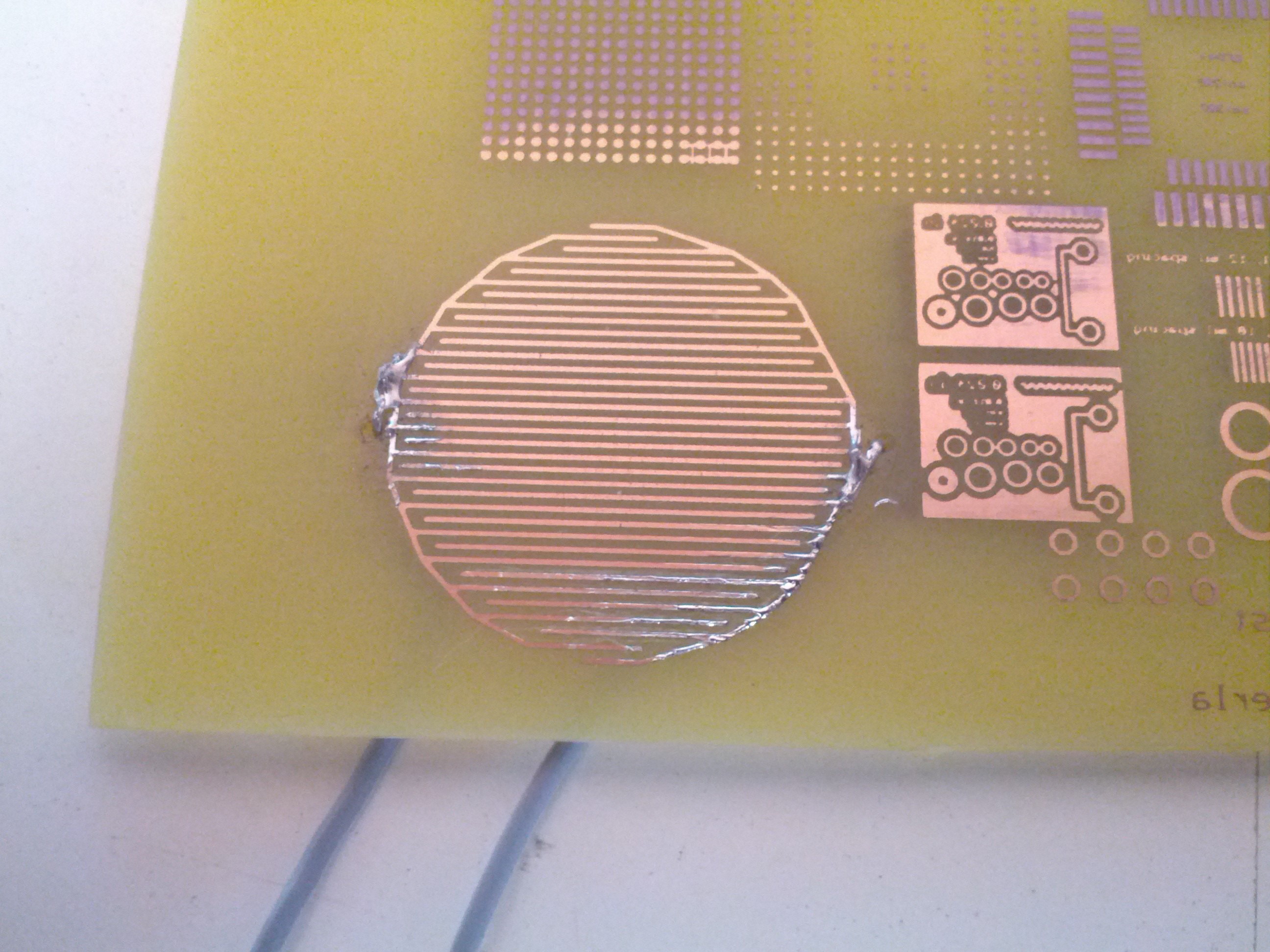
But I assure you that the pads are fully functional; in fact, the test PCB I drilled was an FSR etching test, I tried that with velostat under a pad and it works perfectly! Here's the test FSR:

You can see cables coming out under the PCB soldered to each side of the FSR.
Another issue I encountered while testing that FSR is that there is no way to glue Velostat under the rubber pads; that stuff is unglueable! But I tought of a workaround: I will use an acetate sheet to which I'll glue 16 Velostat circles, and I will cut a windowed acetate sheet (sort of a frame) that will leave some air between the Velostat circles and the FSRs; these two sheets will be put between the pads and the PCB.
Last thing, I still need to design an enclosure for everything; it will have room for the PCB and a base for it, a Teensy 3.x and Teensy Audio Board (for future upgrades), and a motherboard which will host the Teensy and which will have 3 connectors; one will be connected to the FSR board, the other 2 will be free to use with a similar configuration, that is to host a 16 channel multiplexer; this will leave up to 32 addressable analog inputs!
So, stay tuned!
Cheers,
Mick
 Michele Perla
Discussions
Become a Hackaday.io Member
Create an account to leave a comment. Already have an account? Log In.