H00GiE
-
Major Milestone Reached!
12/05/2018 at 16:06 • 0 comments![]()
Caution: More Milestones Up Ahead
Last update I mentioned the screen and the rotary encoder were working on the new software and hardware.
Logic next step is to make the menu system work.
Well finally it's that time, menu system was developed around a totally different system. (WS2812FX project)
So it had to be adapted.
Fortunately the software by Jason Coon is so well written; I could even cut out the middle man code, and control the variables directly: mode/pattern, brightness, speed, Red, Green, Blue (although i might want to switch to brightness and Hue.) are fully synced between the web interface and the screen, and both can be controlled independently and will update on any event. (you can control it on the screen/encoder and it will update the web interface, and you can click any on the web interface and the screen will change in realtime.)
This however, is not the end, there are many more milestones up ahead, here's a few example milestones:- user friendly WIFI.
(set SSID + Secret from menu/web interface/file, switch from AP mode to STA mode) - (optional) Setup mode for number of leds
- Audio Input and reaction.
(BPM mode/pattern should get a beat signature from the audio input.) - [PRO version] DMX / WIreless DMX input.
- Final design V3 hardware + cable management, and enclosure/product design.
- Documentation, instructions and manual.
Pics or it didn't happen!
You're absolutely right, time for a beauty pic:
![]()
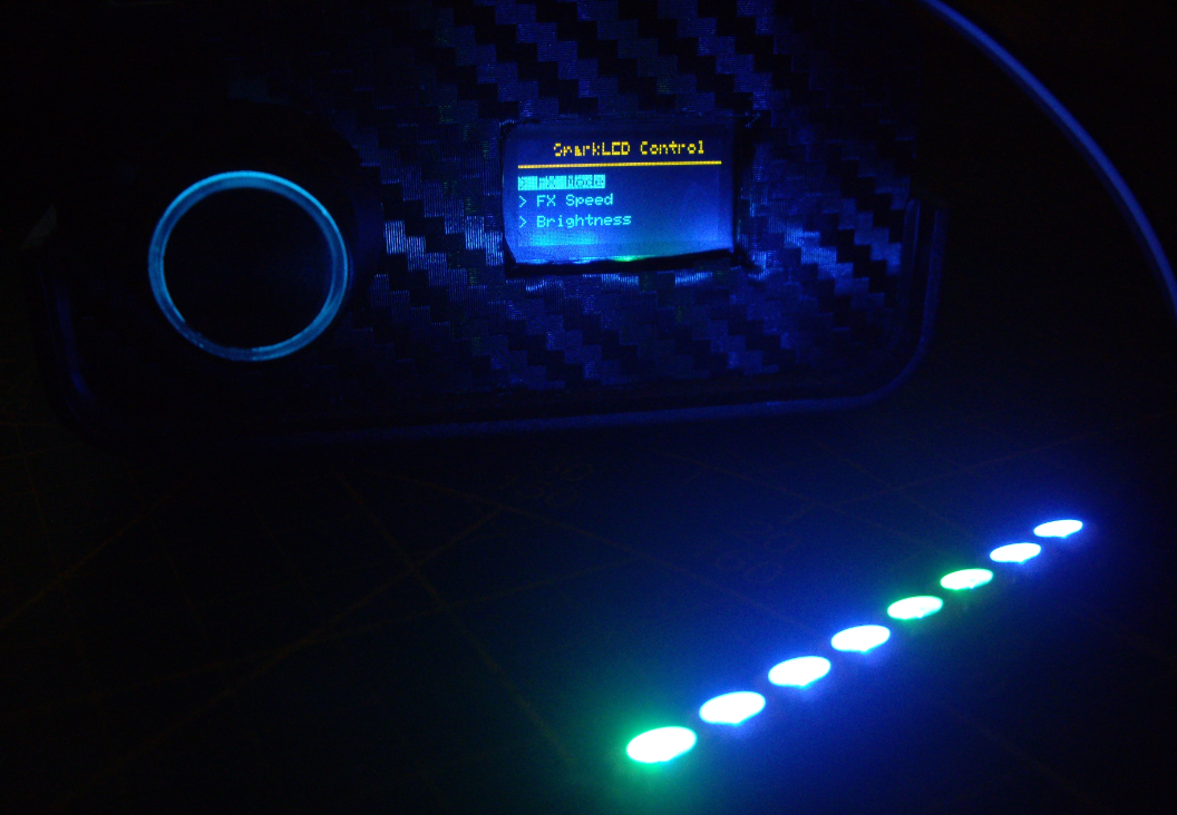
This is the menu showing on the Prototype.
I'm using a adafruit 8 x 5050 bar as testing led strip.
2 lines on the yellow part of the OLED display are broken, so the letters may look weird/broken.
The led strip is so ungodly bright, I had to make the shutter-speed extremely short not to over-expose the image, hence the dark surroundings.
The picture however does give a rather nice representation of how the finished product will look in the dark.So What's Next?
Obviously the list of milestones describes above is leading.
The major priority is debug and adding the user friendly WIFI configuration.
the debugging should be done in the next few days.
I might actually rewrite the menu system to optimize for Jason's software,
because i had to dirty patch the menu to work with the WS2812FX libary.
It would be best to go back to clean code.![]()
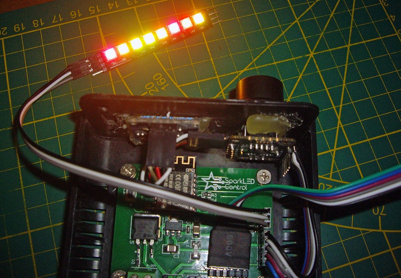
the prototype internals, yes it's riddled with hotsnot (hot glue) and scratches gaps and other unwanted things, but that's what prototypes are for.
As far as the hardware redesign concerned, i was going to switch all the connectors to JST XH 2.54mm pitch connectors.
So to build the prototype i bought a box of assortment JST connectors. However my crimp tool does not have the correct size dies installed, so i'll be ordering a new crimp tool..
Advise on tools is appreciated, i'm looking for a semi budget tool to crimp the tiny JST XH leads, not the unusable cheap ones, and neither the > $100 ones. - user friendly WIFI.
-
Cutting the wire
11/28/2018 at 13:05 • 0 comments#deadline
Various deadlines have come and gone, and i'm painfully aware the project will probably NOT be ready for shipping in 2018.
However i'll be trying to have 5 test variants ready for my closest supporters and friends, this however will "just" be the standard version.
Version?!?Yes I might have mentioned before i'm also making a rugged version of the project for professional/stage usage.
The SparkLΞD Control PRO will be mainly have better materials, lower % deviation on components, aluminium case,
external (replaceable) antenna and optional audio and something special...
As a special feature, the SparkLΞD Control PRO will have full DMX support.
Similar to a DMX Gobo Spot it will have DMX light desk controls available.![]()
The gobo selector will control mode, the iris control will set intensity, RGB / Color respectfully will control Red, Green and Blue balance for color balance within the Mode, and last but not least, variation or another selector will change Program speed/BPM. Any light operator with experience on moving heads with gobos will have no problem working with the controls of SparkLΞD Control PRO.
NOTE: Manual BPM/Speed selection is possible, however the goal is to have the Audio input module generate a bpm clock sync pulse and a external clock sync input to function as trigger within the LED programs.
As standard the DMX signal will use USITT DMX512A and i'm thinking of adding support for Wireless DMX (LumenRadio) RDM ANSI E1.20. just have to see how much a RDM module will cost. Or if there are other options.![]() The Future Is Bright!
The Future Is Bright!
Pun intended, 2019 will be the year, both SparkLΞD Control and SparkLΞD Control PRO will be ready.
Check for updates regularly, it might actually happen i'll still finish the project before holiday season. -
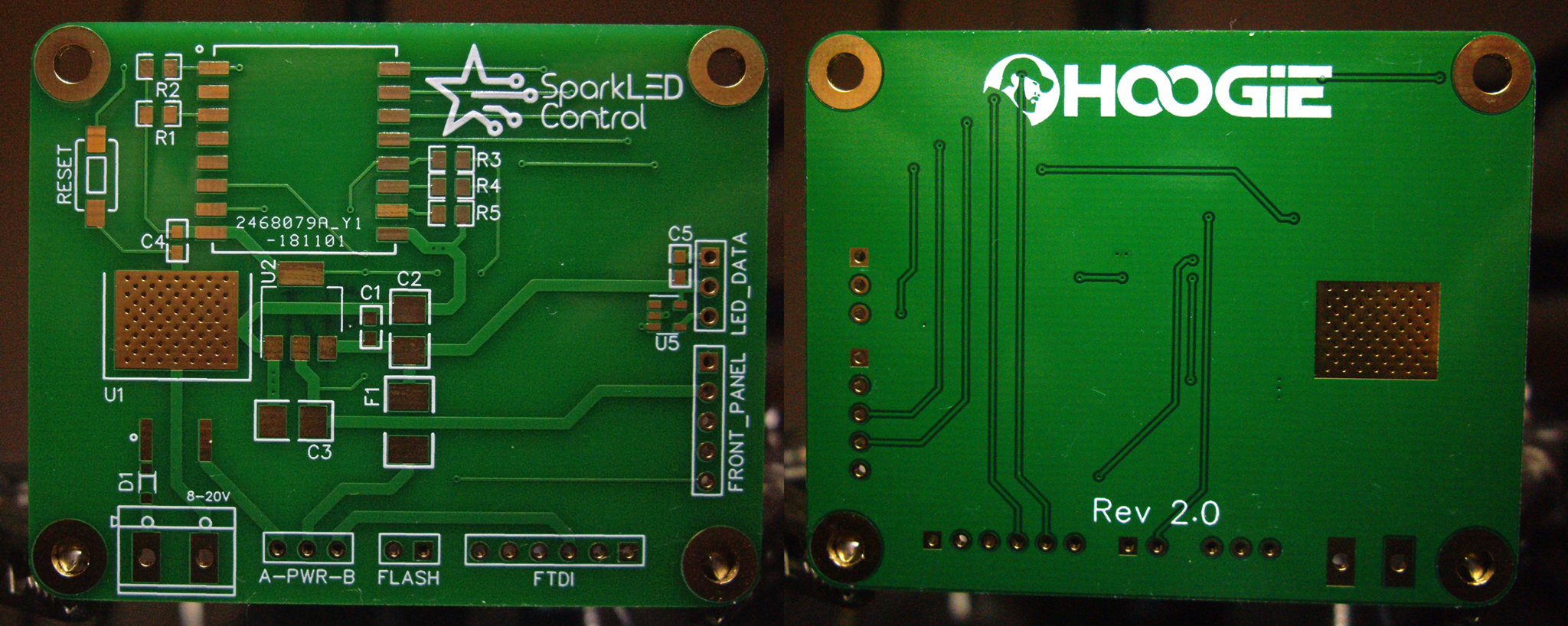
V2.0 Boards
11/15/2018 at 21:48 • 0 commentsNew Design
The new boards (HW v2.0) were redesigned due to new cabling for the front panel.
(everything is I²C now)![]()
New materialThe new PCB is made with ENIG, a type of surface plating used for printed circuit boards. It consists of an electroless nickel plating covered with a thin layer of immersion gold, which protects the nickel from oxidation.
ENIG has several advantages over more conventional (and cheaper) surface platings such as HASL (solder), including excellent surface planarity (particularly helpful for PCBs with large BGA packages), good oxidation resistance, and usability for untreated contact surfaces such as membrane switches and contact points. -
Time to give the project a real name.
10/17/2018 at 19:55 • 0 commentsAnniversary
It's been a full year when I started this project with 2 arduino nano boards,
and around this time last year I finished my very first bit of arduino code (that worked).
For many of us this is not very special, but for me it is, I hadn't written any code in 15 years time,and had 0 experience with C (arduino).
State of the project
Right now there are 3 bits of big code:
- The Wifi enabled Web Interface (by Jason Coon and adapted by Me)
- The actual Led Code including the patterns and (3D) mapping. (by Jason Coon)
- The Menu Code (by Me) with I²C OLED screen + I²C Rotary encoder (Duppa.net / Simone)
All 3 work really well. Most features of Items 1 and 2 even work great together.
The menu is completely new and not yet compatible with the rest of the code,
as it was intended to work with the WS2811FX library.
So my task for the next few weeks is simple, all working code has to be smacked together and work.
But everyone knows, one tiny bit of code works like a Mentos getting dropped in a full Coke Light bottle.![]()
Expect Fun New Code in the next few weeks...
If you'd like i'll add the snippets of code where i'm testing various connections between the menu and the controller and screen, the Led code and the menu, and whatever i'm testing.
Update<Insert Exclamation Here> The Final parts arrived to test putting all Menu I/O over I²C bus, and change code!
So like said above i'll finally be working on that menu system.
Also I've decided to give a REAL name to this project and i'm calling it: SparkLED Control![]()
Created a new logo, banner, photos, all to dress up the project and make it even more appealing.
I'm planning to run a Kickstarter next year to produce the end result as a semi mass produced non prototype.
Keep checking in, as more updates Soon. -
Project update.
08/13/2018 at 17:10 • 0 commentsState of the project.
So far we had a few hiccups:
ESP-07 only comes with 1MB flash, I used the instructions on a video by Andreas Spiess (click) to upgrade my ESP-07 to 16MB.
Overkill?? yes, but i only had a 16MB (128mb) flashchip available.
I'll be upgrading to 4MB chips on other ESP-07 modules.
Like to try yourself? Watch this video:
This is the result after uploading TREE V2 (click) firmware:![]()
So with this success i'll be buying a few more modules, and will switch the flashchip.
I have ordered enough 25Q32 (4MB Flash) to replace all my ESP-07 modules' flashchips.
Why the ESP-07?Easy one: The ESP-07 is the only 8266 family with BOTH a Ceramic wifi antenna as well as a u.FL (IPEX) connector for optional outdoor use. (More on this in a next update.) And simply said: The ESP-07 module is pretty much the very CHEAPEST ESP8266 around to make this project stay low cost.
What's next?
I'm waiting on testboards of the I²C Rotary controller (click), so i can adapt V2 design if necessary.
If the design i have works and the board is finished i'll be ordering a batch of V2 PCBs.
When I receive the rotary encoder I can start work on the new firmware adaption as well.I have communicated (briefly) with Jason Coon and he is okay with me using his software, If I share alike.
So very soon i'll be making this whole project opensource, both hardware designs, gerber files etc and customized version of the TREE v2 software will be uploaded to github. (more on customizations later)
⭐SparkLΞD Control
A ESP8266 based controller for Individually addressable LED Strips and Strings, with 3D map, OLED / Rotary controller Menu and Web UI.


 The Future Is Bright!