deʃhipu
-
More Blinking Lights
08/16/2018 at 16:02 • 1 commentThe PCBs arrived from @Elecrow today, and they look great.
![]()
There is one mistake I made — one of the traces is connected with one of the pads of the battery holder. That's what you get when you move the parts slightly just before sending the design for fabrication. Fortunately it's easy enough to cut the two apart.
With the hardware ready, I need the software. In this case this simple code for attiny13 works:
#include <avr/io.h>
#include <avr/pgmspace.h>
#include <util/delay.h>

#define byte unsigned char

#define COL0 PB0
#define COL1 PB4
#define COL2 PB1
#define COL3 PB3
#define COL4 PB2

const byte PROGMEM VALUES[] = {
    (COL0 << 4) | COL4,
    (COL0 << 4) | COL3,
    (COL0 << 4) | COL2,
    (COL0 << 4) | COL1,

    (COL1 << 4) | COL4,
    (COL1 << 4) | COL3,
    (COL1 << 4) | COL2,
    (COL1 << 4) | COL0,

    (COL2 << 4) | COL4,
    (COL2 << 4) | COL3,
    (COL2 << 4) | COL1,
    (COL2 << 4) | COL0,

    (COL3 << 4) | COL4,
    (COL3 << 4) | COL2,
    (COL3 << 4) | COL1,
    (COL3 << 4) | COL0,

    (COL4 << 4) | COL3,
    (COL4 << 4) | COL2,
    (COL4 << 4) | COL1,
    (COL4 << 4) | COL0,
};


int main() {
    while(1) {
        for (byte i=0; i<20; ++i) {
            byte value = pgm_read_byte_near(VALUES + i);
            DDRB = _BV(value & 0x0f) | _BV(value >> 4);
            PORTB = _BV(value >> 4);
            _delay_ms(18);
        }
        DDRB = 0;
        _delay_ms(740);
    }
}
I made it a bit more complex than it could have been, but the basic idea is that I put the desired rows and columns for each LED in a table, and then I just loop over it to create the animation. It's really simple, I have no idea where the 150 bytes of flash this program takes come from. Oh well, it fits anyways. Here's a horrible GIF showing the animation:
![]()
Now I'm going to send it to a couple of people for testing, and I'm going to work on the actual "smart" barrette — the one that can control all your blinking jewelry.
-
Blinking Lights
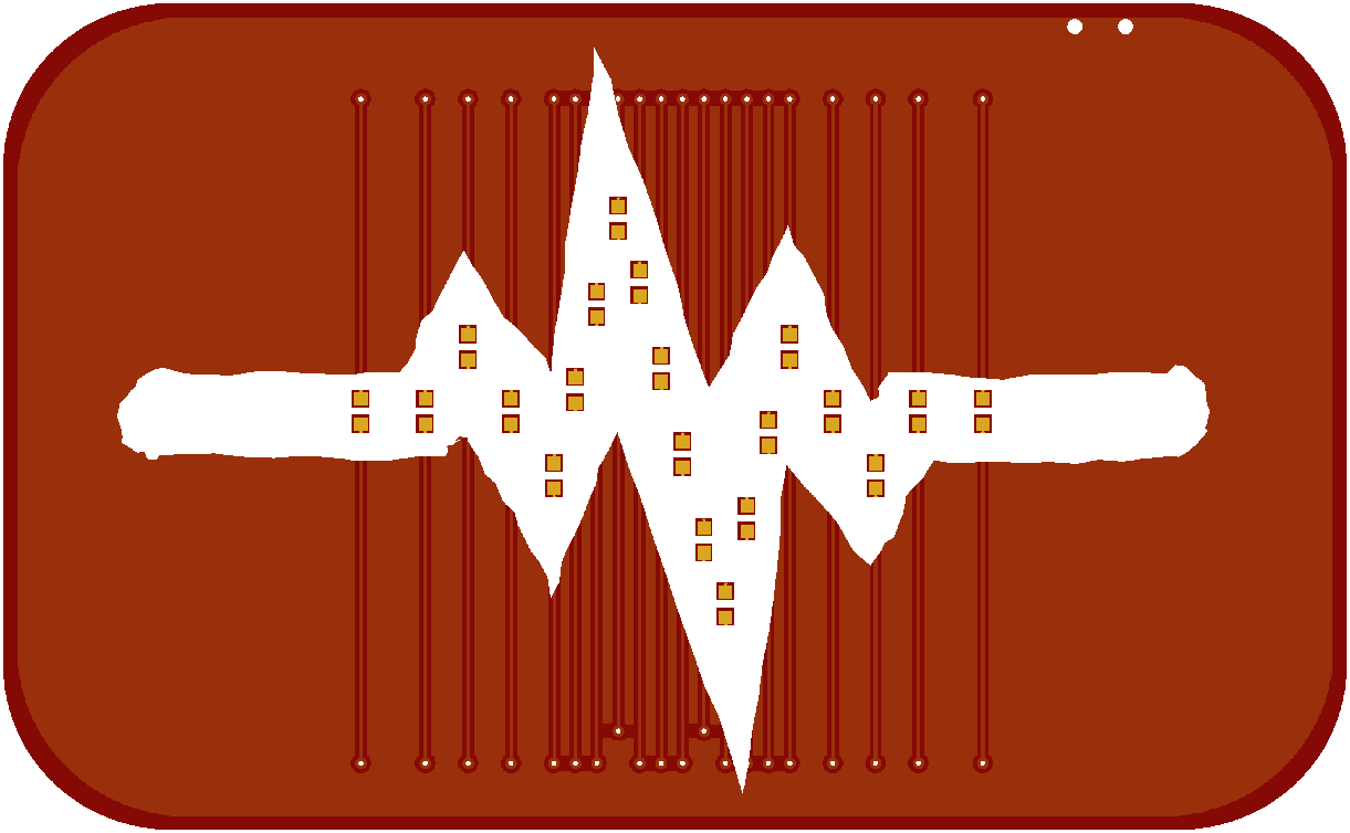
08/04/2018 at 08:33 • 0 commentsWith the clasp out of the way, it's time to design the actual PCB. I decided to start with something simple: a signal line, like a heartbeat, with LED lights running along it. With 5 gpio pins of an attiny45 I can get 20 LEDs if I charlieplex them, so let's try that.
![]()
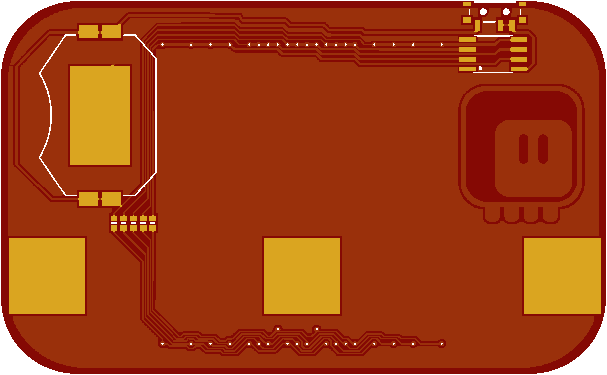
Unfortunately, charlieplexing requires some rather complex connections, so I will need traces on both sides of the PCB. I tried to at least make them look consistent, so that they won't be too jarring. The back of the board is a little bit more complex:
![]()
As you can see, there is some fine detail in there. That braid on the bottom almost looks like a decorative pattern — maybe I will use that in some other design. Otherwise, there is nothing special here: battery, attiny, power switch, resistors and three pads for soldering the clasp.
The PCB is now ordered and when it arrives I can start programming.
-
Preliminary Tests
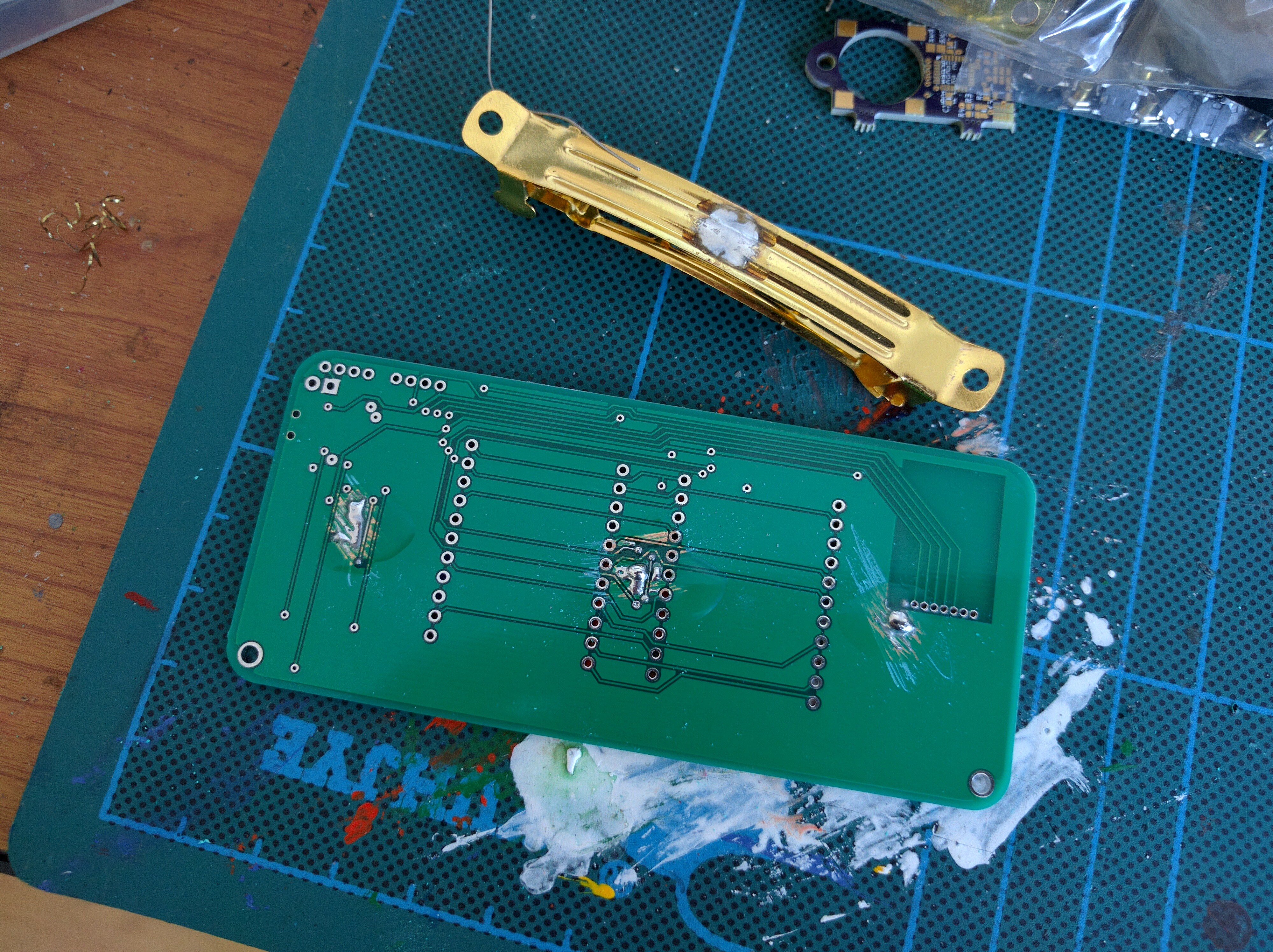
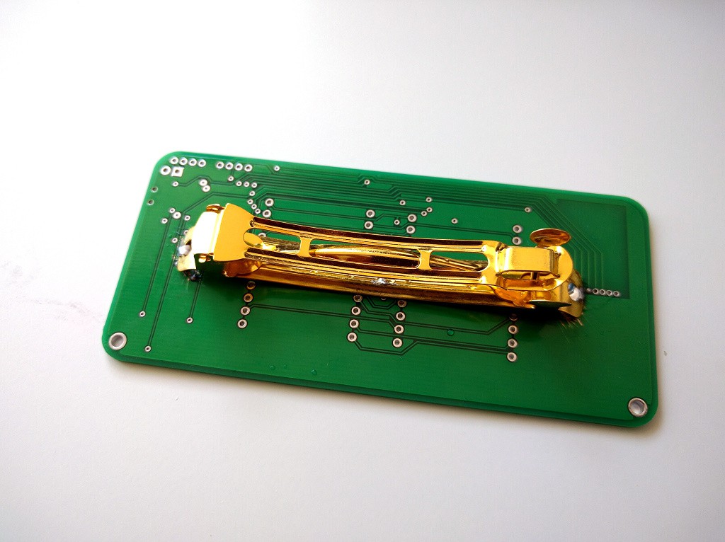
08/04/2018 at 08:25 • 0 commentsThe clasps I ordered a while ago have just arrived, and it's time to make a practical test of attaching them to a PCB. For that I used one of the old PCBs I have in my box. I scratched the soldermask in three places and tinned it with solder. Then I straightened the clasp a little, bent the ends so that the contact points are all in a straight line, and tinned them.
![]()
Next, I put the two together and heated with my soldering iron. The result looks pretty good, and is really strong and solid:
![]()
More importantly, the clasp still works, even after being attached to a rigid PCB like this. It's a little too big for wearing — because the PCB is straight, and not bent, the ends stick out to the sides too much. The actual barrette will need to me a bit shorter.