-
1st characterization step
08/21/2018 at 21:16 • 0 commentsAs in any incremental development, we tried to get a simple working version to characterize it and improve it accordingly.
HTC Vive system consistency
The 1st step was to verify that we can measure a coherent 10 mm translation wherever we are in our interaction zone.
We used a CNC to sample positions along a line that can be seen in the following video:
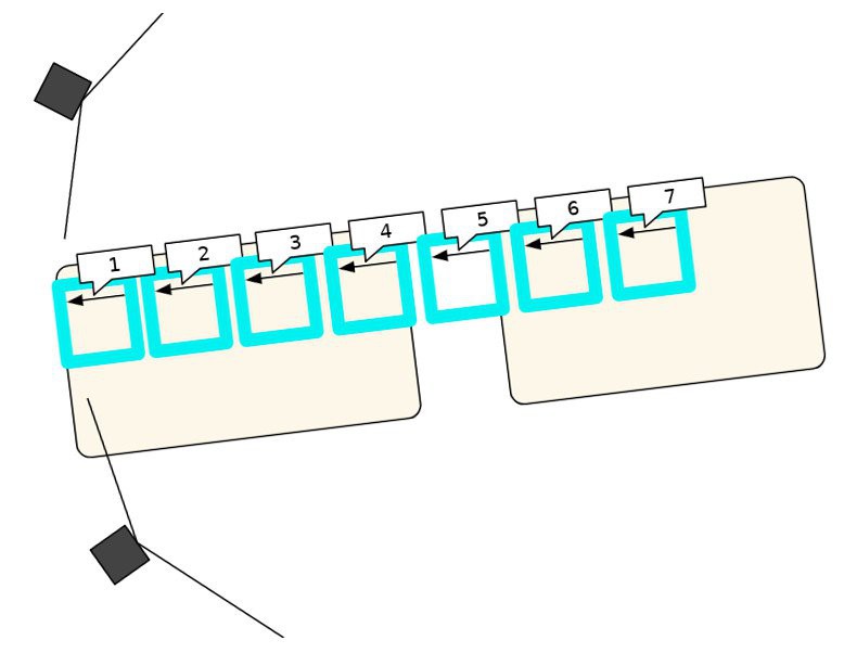
As represented in the picture below, we moved the CNC on 7 locations to have a reasonable overview:
![]()
Distortion
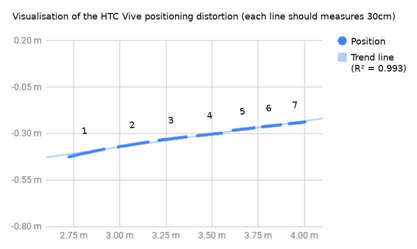
You probably saw it coming, the HTC Vive positioning system is not linear depending on the bases placements.
![]()
It makes sense, and it's actually OK as a distortion map can be estimated, and real positioning can be predicted from it.
Jitter
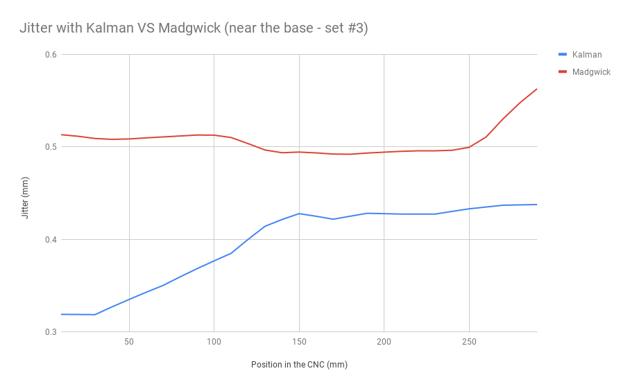
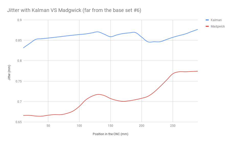
A better filter characterization will be published soon, but the below measures were captured for the position #3 and #6, they show the measured noises in average, depending on the chosen algorithm:
![]()
![]()
You might have noticed that in our current Madgwick and Kalman implementations, their performance is complementary depending on the distance.
Overall, the accuracy can be estimated below 1 mm when far from the bases, and around 0.5 mm when close to the base.
-
3d Positioning is working!
08/05/2018 at 09:51 • 0 comments1 picture is worth 1000 words, here are a moving ones!
Here we basically demonstrate the principle of out positioning approach:
The bases send their laser sweeps, we measure the timings, convert them to 3d angles, and observe the 3d intersections.
This is made in this blender visualization:
https://github.com/HiveTracker/Kalman-Filter/blob/master/visualisation.blend
The math behind this idea is derived here:
https://docs.google.com/document/d/1RoB8TmUoQqCeUc4pgZck8kMuBPmqX-BuR-kKC7QYjg4/
Finally, the 3d models are available here:
https://github.com/HiveTracker/Kalman-Filter/blob/master/Frames
-
Libraries validations
08/05/2018 at 09:51 • 0 commentsOpen source != easy
Sharing software or hardware is not the only step to make open source projects accessible.
Developing with open programs, and affordable tools are important aspects too.
But many embedded systems purists would never accept to use Arduino in a serious project, and from the difficult Twiz experience with users, it seemed important to find a trade-off.
Luckily, the excellent work by Sandeep Mistry allows it reasonably:
github.com/sandeepmistry/arduino-nRF5
Hello world
Once the environment validated, it was possible to test the boards, it might seem simple but blinking LEDs can sometimes be very challenging, mostly in the Chinese manufacturer's office:
photos.app.goo.gl/LxQBnC5XiCdQhxJa7
Complex features
Back home, it took a while to validate all the firmware components.
The most complicated being the PPI, we found inspiration in the ex-arduino.org repos, and got it to work:
To reach this point, many steps were necessary, but the main trick was to use a logic analyser.
The one visible here was made by saleae, but for those with small budget, aliexpress has a few affordable alternatives.
For those who only work with open tools, Sigrok can help, but the software by Saleae is free + cross platform and is quite practical:
![]()
-
1st Hardware prototype
08/05/2018 at 09:50 • 0 commentsWith the miniaturization idea validated, we focused on using only 4 photodiodes as putting them on a tetrahedron allows having at least 2 visible ones by the lighthouses, for any rotation.
Main parts
- MCU + BLE: To save some space, we use a fairly small nRF52 module (8 x 8mm) by Insight.
- IMU : To save some time, we use the only 9DoF sensor that performs the full sensor fusion, the bno055 by Bosch.
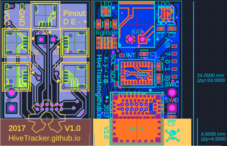
The PCB design files are on upverter.com/hivetracker, but here is an overview of what it looks like:
![]()
It was finished and built during yet another Hacker Trip To China, hanging out with the Noisebridge gang and tinkering with magic parts found in the Shenzhen electronic market.
Making in China
Note: there are 2 periods of 1 week when almost everything is closed in China, lunar new year is probably the most famous, but the golden week holiday is very serious too.
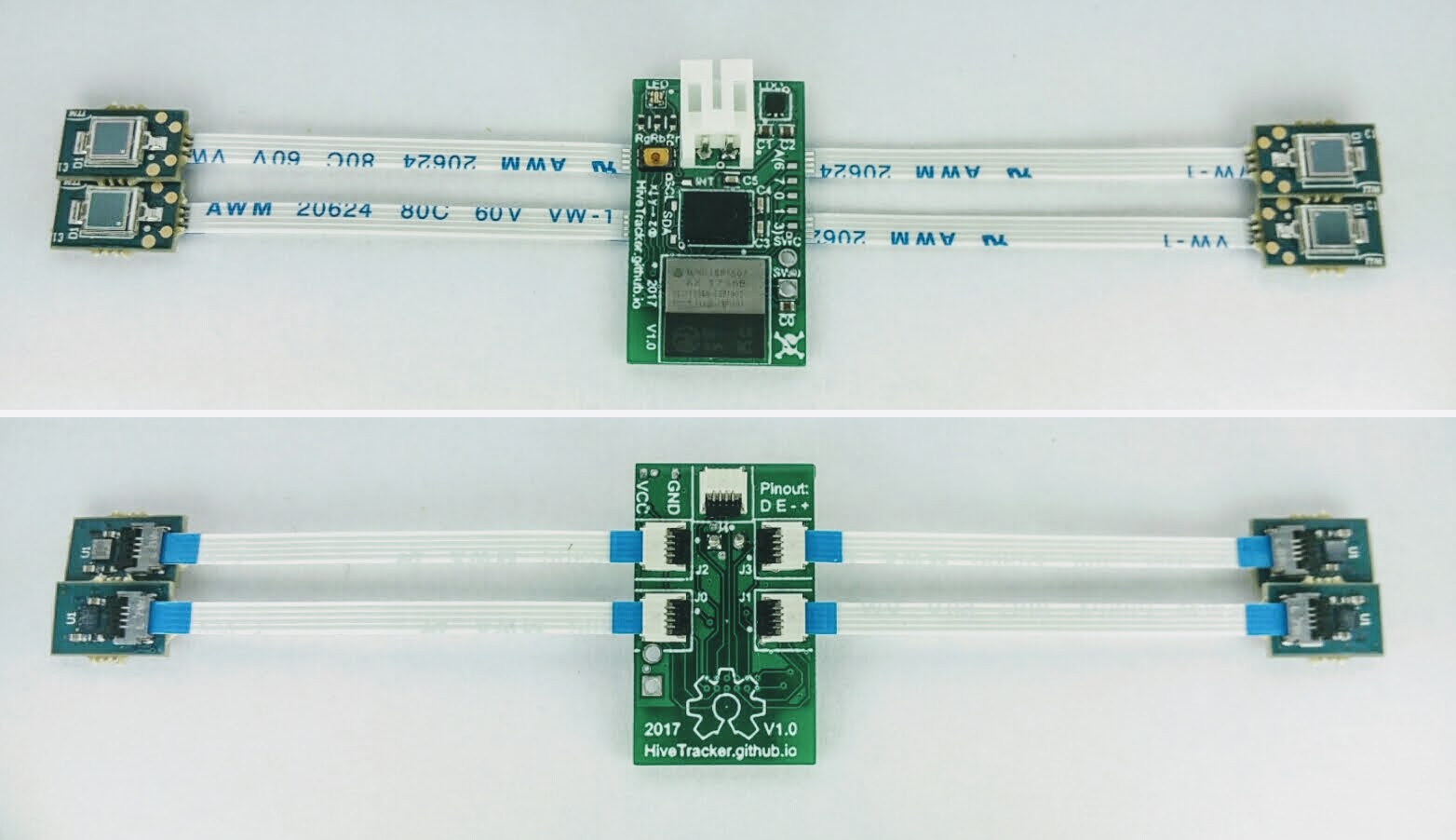
This board was made during the golden week so it was not easy, but even though some chosen parts are approximative, some manufacturers such as smart-prototyping.com are more flexible and they got the job done:
![]()
-
Miniaturization Idea Validation
08/05/2018 at 09:50 • 0 commentsTo miniaturize the HTC Vive tracker, we needed to make our own board, and went through several ideas, here is a summary:
Problem
To achieve accurate timestamps of several photodiode signals in an MCU, using interrupts would not be ideal as they would add delays and we would miss some of them.
1st idea
We 1st thought about using the tiny FPGA by Lattice (iCE40UL-1K), it's only 10 x 10 mm and can be flashed with the Ice Storm open source tool-chain: clifford.at/IceStorm
Trick
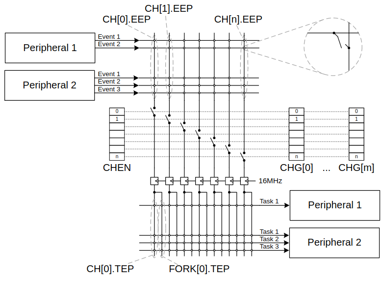
...but we were planning to use the nRF52 radio-MCU by Nordic, and remembered that it has a very practical feature that would allow doing those timestamps in parallel without interrupt.
This feature is called PPI Programmable Peripheral Interconnect:
![]()
Validation
To verify that the timings were possible, we enjoyed the great talk* by Valve's engineer Alan Yates:
This video helped us simplifying our feasibility estimation, below are the quick & dirty numbers:
- Max base to tracker distance = 5m (5000mm) and we want an accuracy 0.25 mm = Ad
- Motor speed = 60 turns/sec => 1 turn takes 1/60 = 16.667 ms = T
- During T, the travelled distance = 2 Pi R = 31.415 m = D
- Time accuracy = T / (D/A) = (1/60) / (2 Pi * 5 / 0.00025) = 132.6 ns = At
- PPI sync @ 16MHz => 62.5 ns = Tppi
=> Theoretical accuracy = Ad / (At / Tppi) = 0.25 / (132.6 / 62.5) = 0.118mm!
*Video source:
https://hackaday.com/2016/12/21/alan-yates-why-valves-lighthouse-cant-work/
-
Proof Of Concept
08/05/2018 at 09:49 • 0 commentsHistory
Before diving in the proof of concept, it's worth reminding what was available before.
The main alternative is a camera based solution and the median cost is $1999:
http://www.optitrack.com/hardware/compare/
This solution doesn't even scale anyway, above a dozen of trackers it starts lagging.
We also needed to embed intelligence, so we decided to look at what was possible and we made our own.
This project was inspired by various others, here are the fundamentals.
Legacy
First off, from inertial sensing to 3d positioning, we went through various steps of thoughts, analysis and experimentation, here are relevant links:
- Twiz - Tiny Wireless IMUz: hackaday.io/project/7121-twiz
- Wami - Ultrasound 2d positioning: rose.telecom-paristech.fr/2013/tag/wami
- Plume - Magnetic 3d positioning: hackster.io/plume/plume
Inspirations
The followings helped tremendously to understand the details of this system, thanks a lot to them:
- Trammell Hudson: https://trmm.net/Lighthouse
- Alexander Shtuchkin: github.com/ashtuchkin/vive-diy-position-sensor (+ wiki !)
- Nairol: github.com/nairol/LighthouseRedox
1st feasibility test
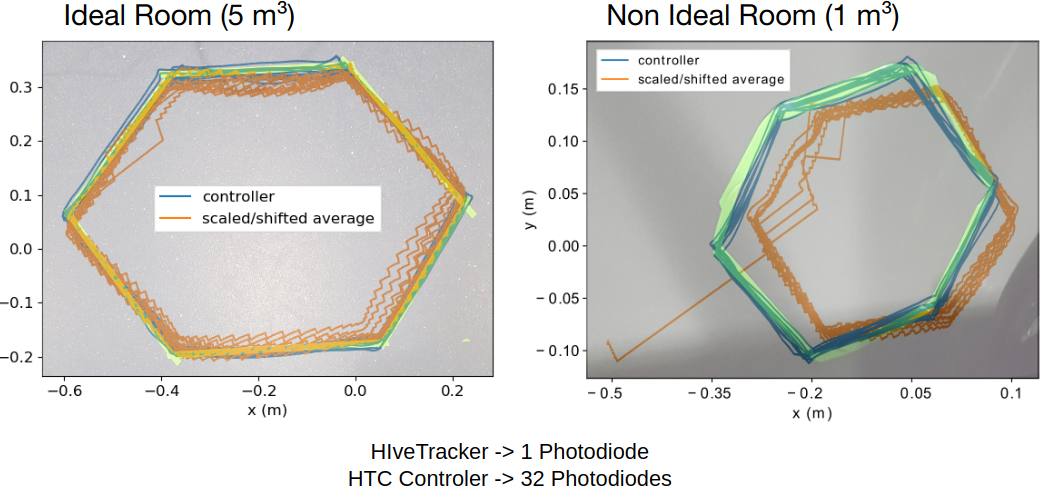
We first replicated the above inspirational approach as proof-of-concept, and compared it against the hand-held controllers of the commercial Valve tracking system in an ideal room. We taped a non-regular hexagonal shape on the floor of the testing room, then traced this shape by hand with both devices, recording the devices’ positions using Bonsai.
Here is a visualisation of the preliminary results:
![]()
This proof-of-concept, which uses only one photodiode, had an average error on the order of 10 mm more than the average error of a commercial tracker.
Although this approach is not pursued anymore, the code is available :
HiveTracker
A tiny, low-cost, and scalable device for sub-millimetric 3D positioning.
 Cedric Honnet