Turns out, openocd is hard for people to use! It's true that it has a billion obscure options, but once you've gone through the pain of using it on a few chips, it just makes sense!
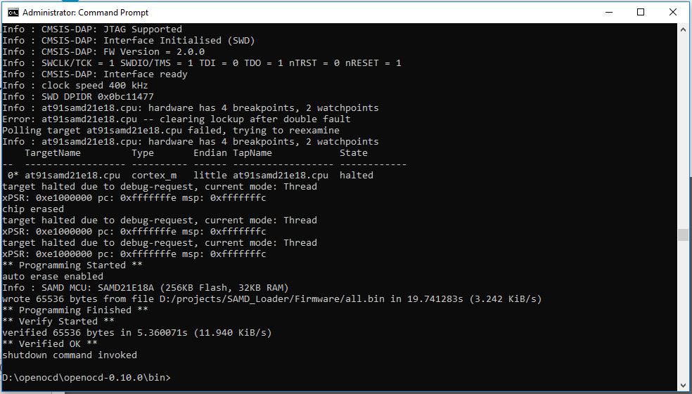
I wanted to add my flashing script (openocd.cfg) here to show an example of a working setup using openocd 0.10 and an STM32 Blue Pill flashed to the CMSIS-DAP firmware. This is what I use to do the initial flash on my boards.
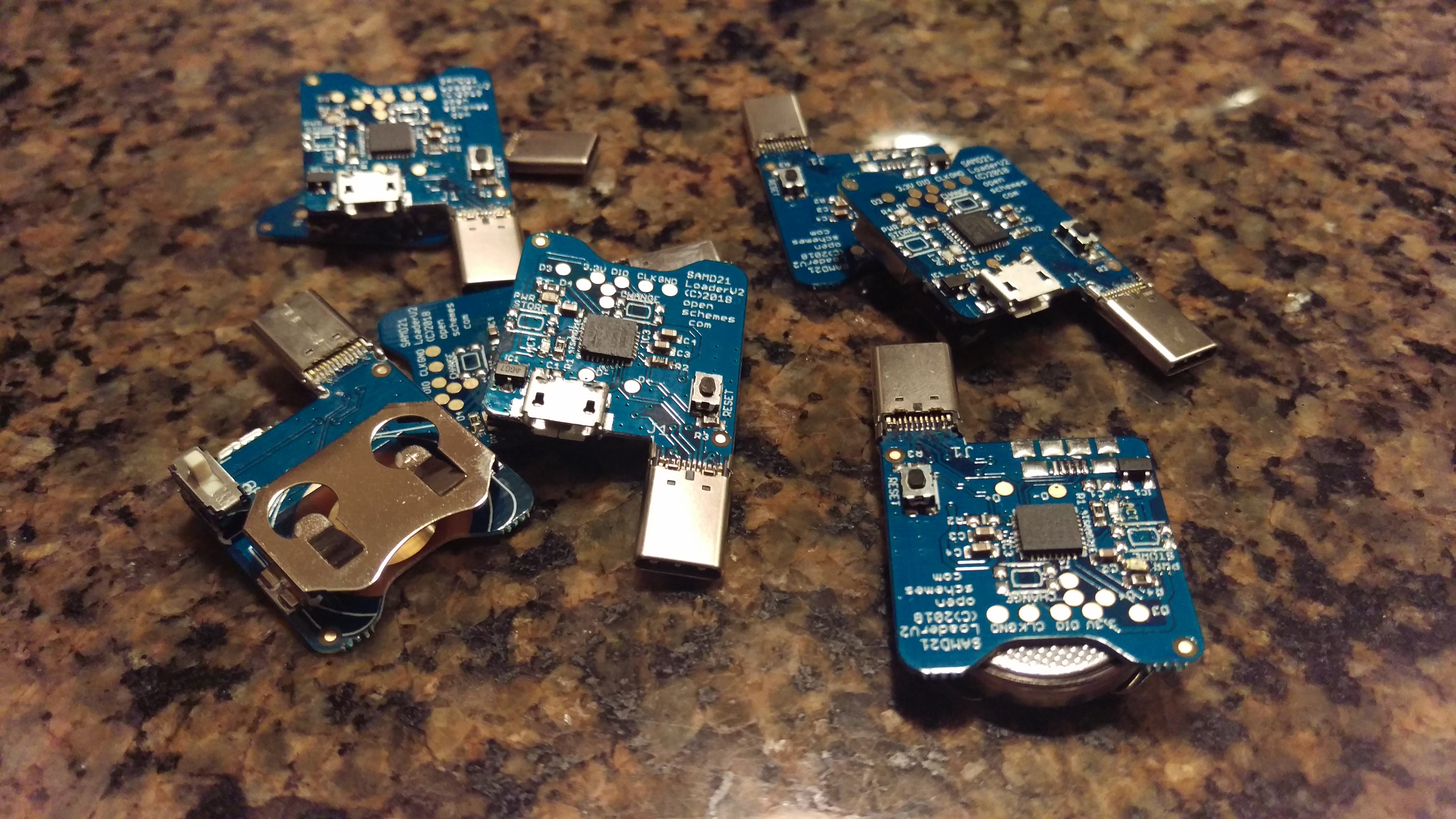
My bin file contains both the UF2 bootloader as well as a fimware, but it's really only necessary to use openocd to flash the bootloader on a fresh chip. After UF2 is on there, you can use USB to drag and drop firmware on very easily. However, it saves a step for me if I flash both of them at once so that's the way I do it.
As for how you merge the bootloader and firmware into a single bin file? Don't ask, it's a bit messy. If you want this bin file just PM me. Cheers!
interface cmsis-dap
transport select swd
#Target
set CHIPNAME at91samd21e18
source [find target/at91samdXX2.cfg]
#source [find target/stm32f1x.cfg]
init
targets
reset halt
at91samd chip-erase
reset halt
at91samd bootloader 0
program D:/projects/SAMD_Loader/Firmware/all.bin verify
at91samd bootloader 8192resetshutdown
Here are the Github links for the source code used in this project. If you want to go a-hacking, you will most likely want the Launcher firmware. The bootloader code is included for those who are interested, but it's not needed unless you are starting out with a factory-fresh chip. After the initial bootloader flashing, all further flashing of firmware, etc is done either through Arduino, or better yet - by dropping a UF2 file onto the USB device itself. (Double click reset to open the USB firmware drive for drag & drop flashing)
Here is a quick demo of the SAMD Loader in action. It's a pretty straightforward operation:
1) Paperclip or use a RCM clip on the right hand joystick slot
2) Power up SAMD Loader, get a fast blue blink (Looking for USB)
3) Hold Vol + and Power up, blinking will pause for a moment as USB enumerates.
4) Short/Long blink (Ta Daa!) signifies sending and launching the payload
5) Enjoy!
Here I am sending SX Launcher, as I just use my own hekate build stored on SD. But I have a firmware that sends hekate directly if preferred. Really, the firmware can be recompiled with any payload you like. To convert a bin file payload to a header for inclusion in the firmware, just use the "bin2header" tool from github to convert.
I flash my firmware using openocd and an STM32 "Blue Pill" flashed to the CMSIS-DAP firmware. I use openocd to flash a bin file that contains both the UF2 bootloader as well as the fusee firmware. It's a bit more convenient to do it all in one shot than to flash the bootloader first and then switch to USB or arduino for the firmware. After this initial programming, I use the USB virtual flash drive from the UF2 bootloader to modify or change firmware as openocd is no longer needed.
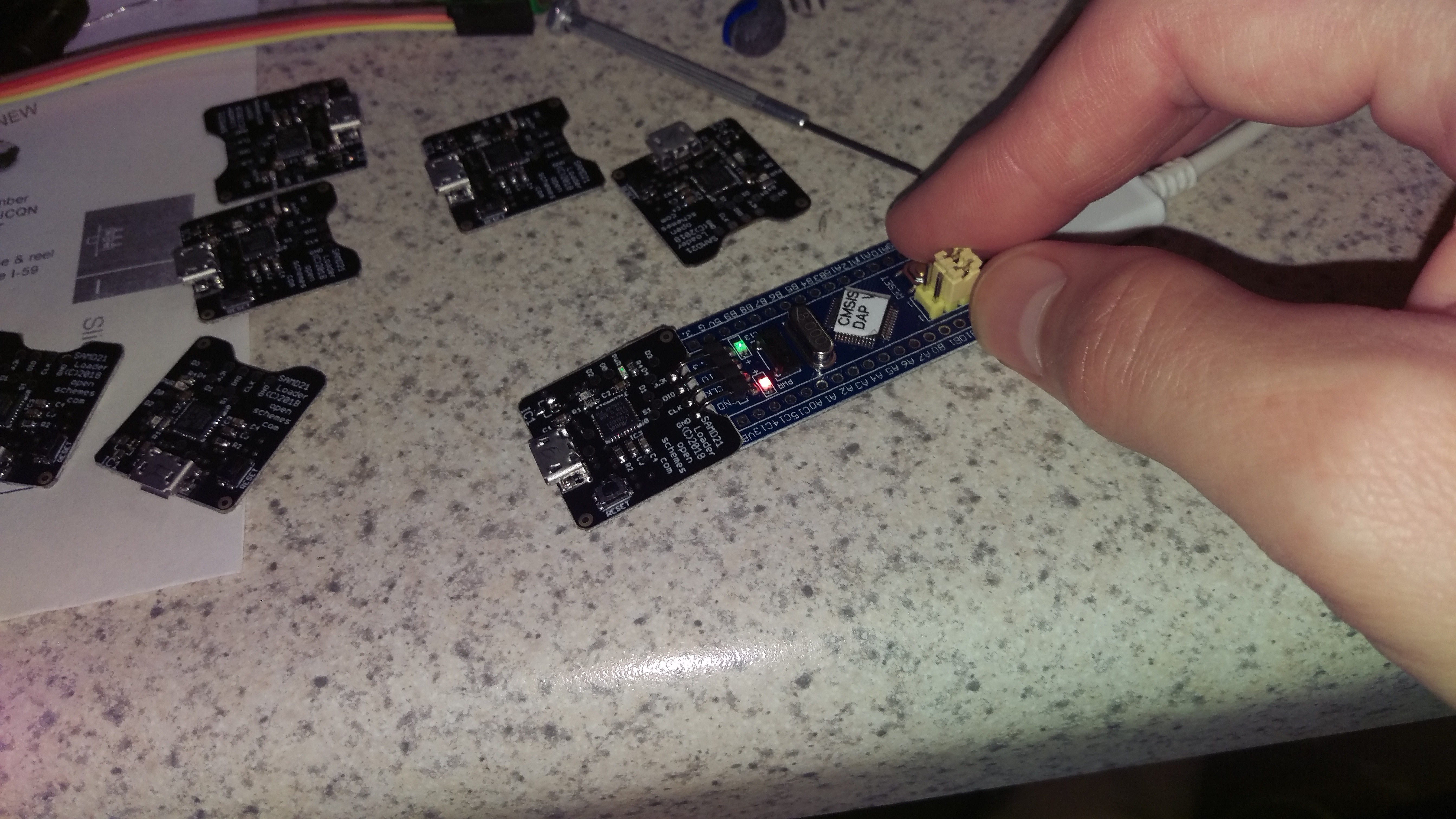
For this project, I just use the blue pill to directly contact the four programming pads I placed on the SAMD board. A little bend in the blue pill headers give a nice springy connection that I can pop on and use to hold the board steady while flashing. This initial flash takes about 30 seconds, so it's pretty quick to do a batch of 10 or 20.
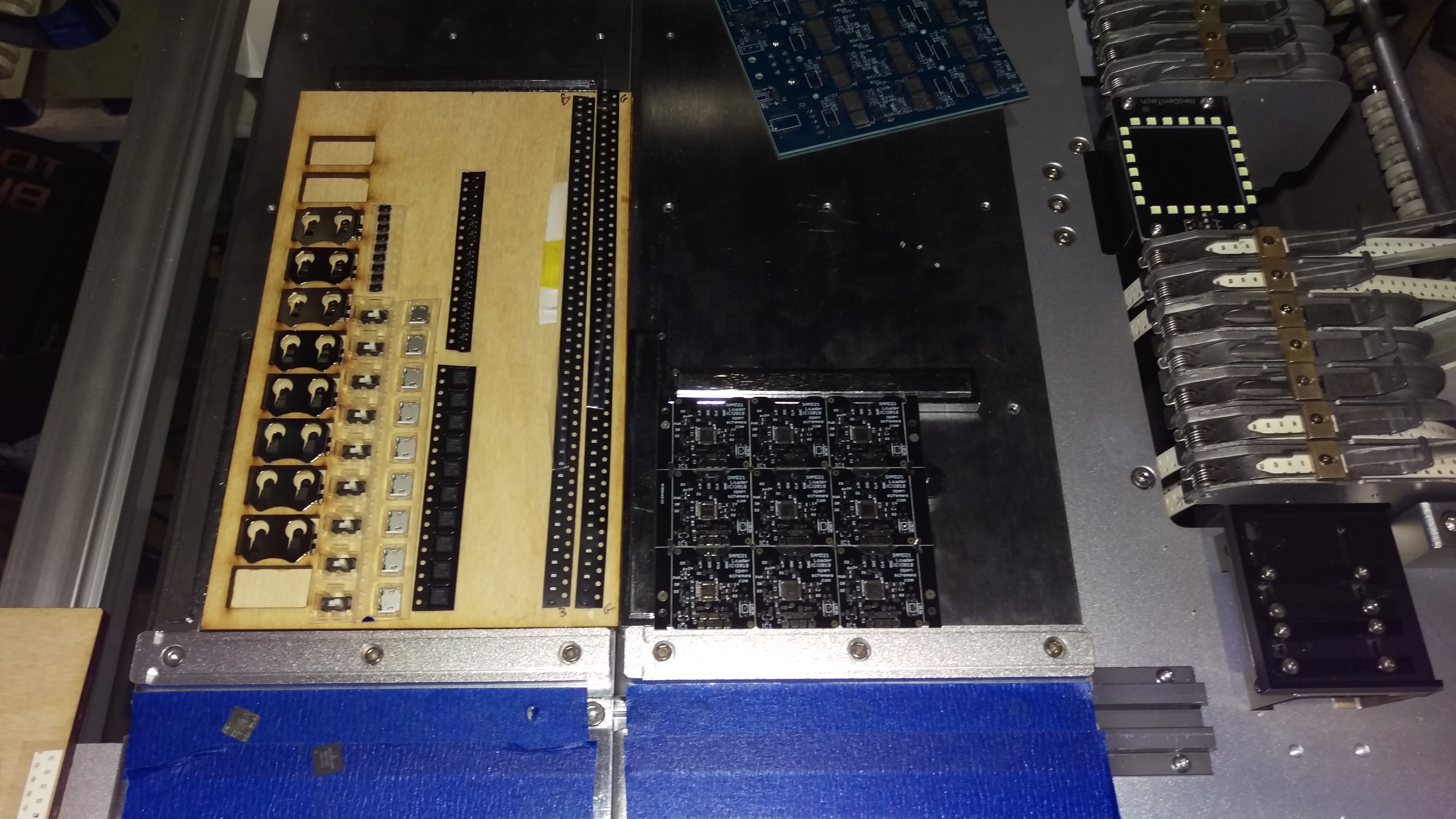
It always takes a few hours to program the pick & place. Here I am using a bunch of components on cut tape, so I just stick them to a board and use the vision system to set the location of the first and last part. That's the first part of project setup for the placer, and takes an hour or so unless you bump a strip of 0603 LEDs and have half of them jump out into a scattered pile. Then, it takes longer. :)
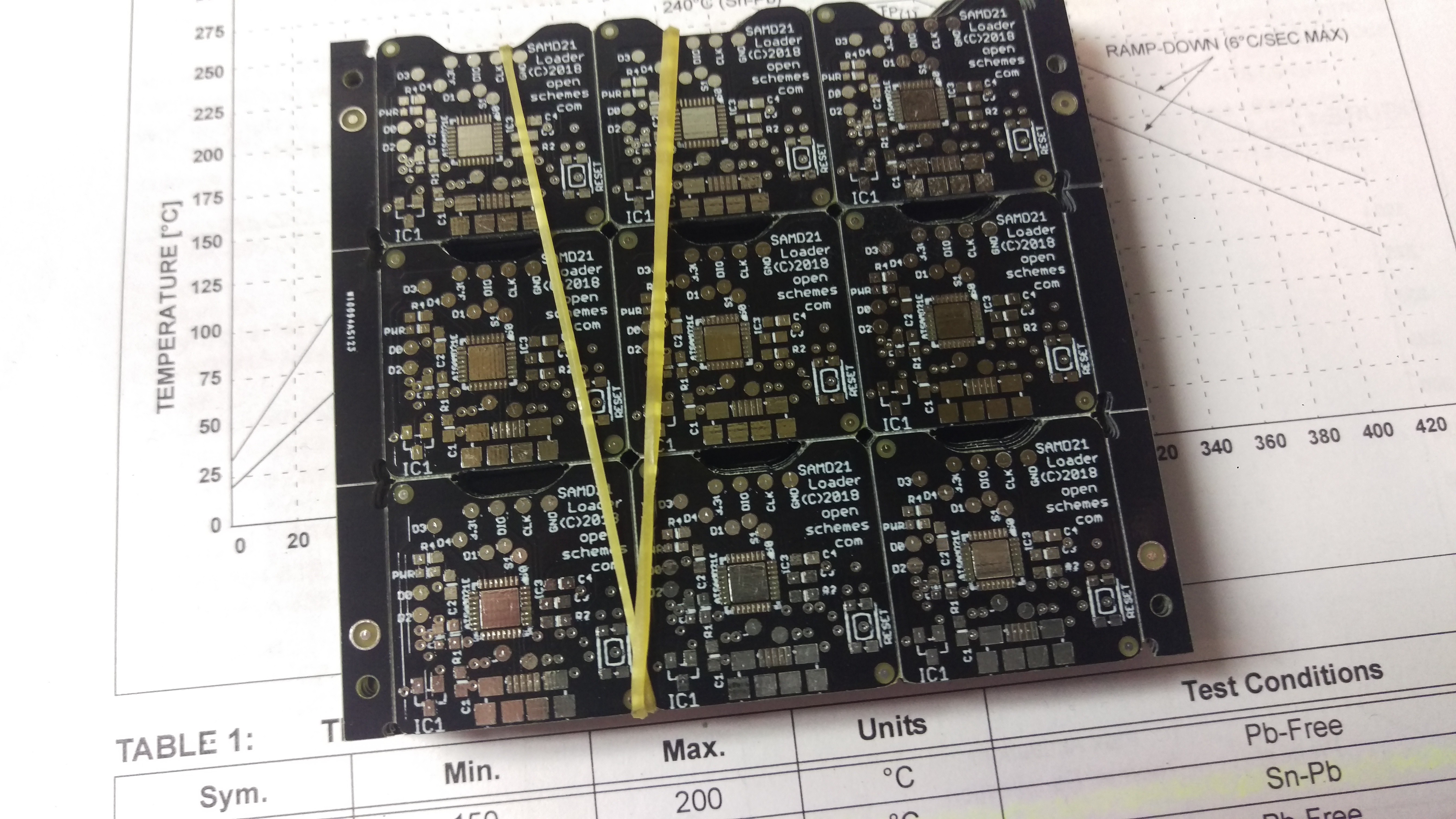
Here you see the PCB panel on the right, and components stuck to a wooden plank on the left. From left, it's Battery Clip, Switch and Reset Button above it, USB socket, SAMD and LDO above that, then two rows of LEDs - blue and green.
Some components like caps are already mounted in reels on the side of the machine, but there are always a handful of custom components (or ones that are too expensive to buy a full reel!!) that I use cut tape for.
The next part of setup is verifying the placement and orientation by running a placing cycle (usually for one component only) with double face tape on the PCB. The machine grabs the part, checks it, and sticks it where Eagle said it should go. It's usually perfect, but a few oddball devices like the USB port had a center location different from what Eagle outputs and need editing.
It's tedious, but if you're making a bunch of boards it is much easier to take the pain now in exchange for MUCH faster assembly than doing it by hand.