V 5.1 is a general refinement sweep
That brings a revised wave generator, fixed spline, and output shaft assembly. There are now 3mm dowel pins of various lengths (40mm, 14mm, 8mm) placed throughout the fixed spline as well as output shaft assembly for precise mating and added structural support.
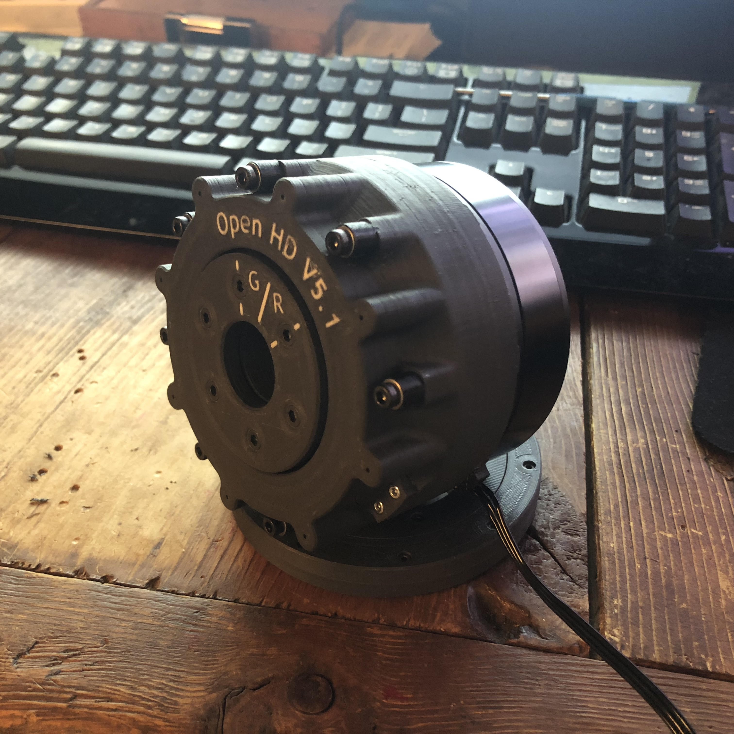
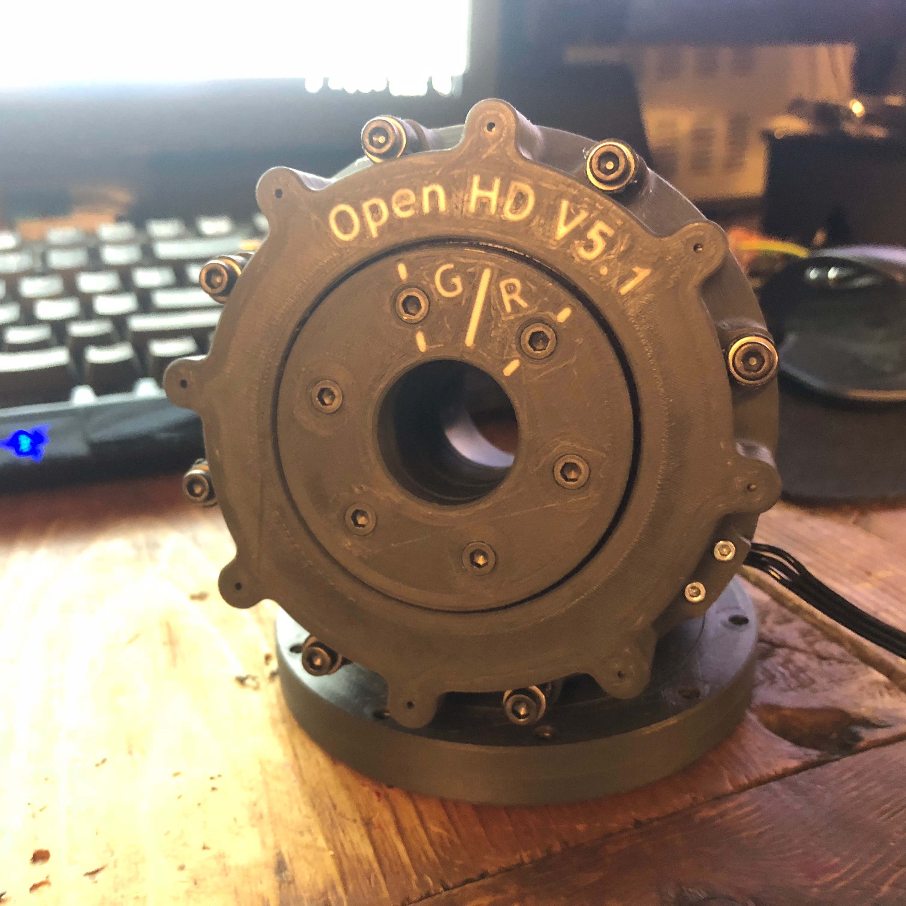
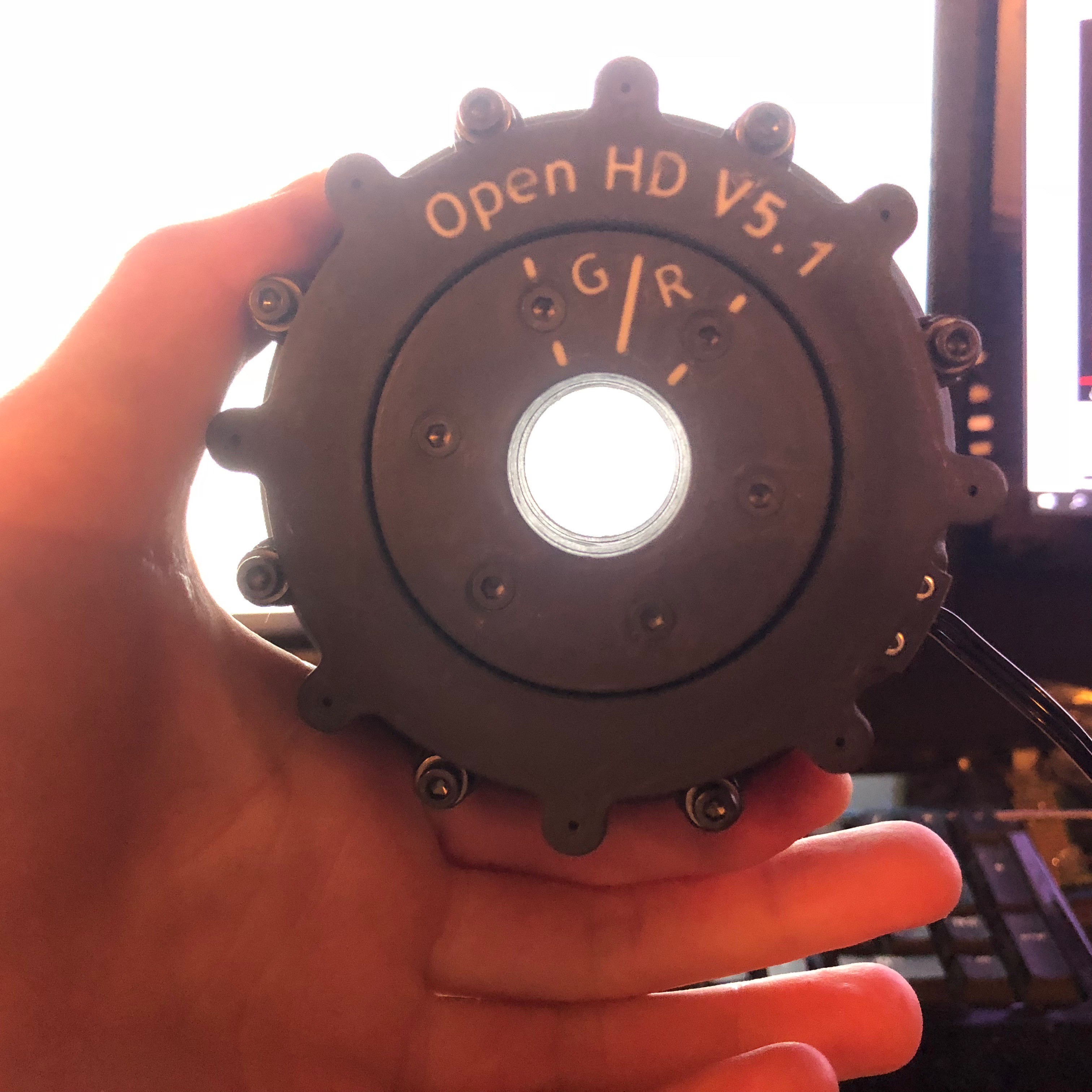
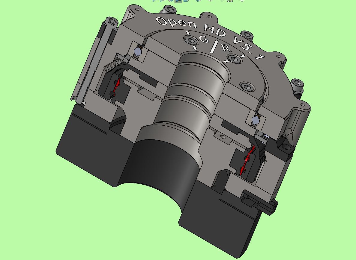
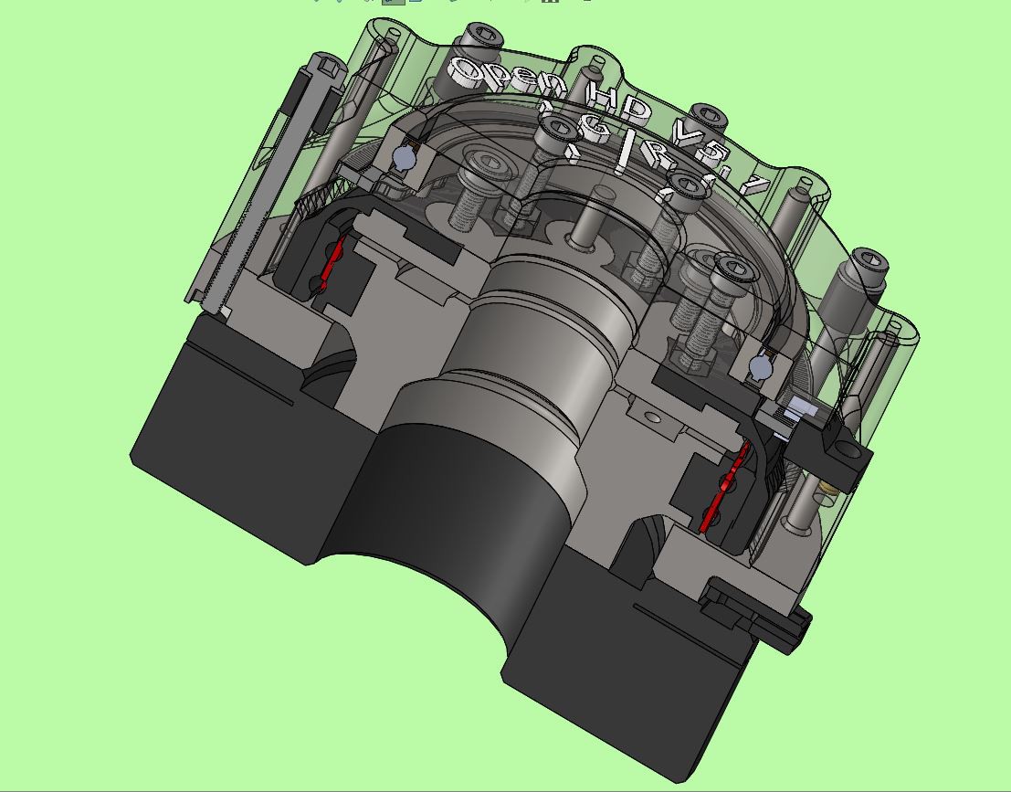
Changes to the wave generator were primarily processes focused to make their manufacturing simpler to automate. List of component changes:
- Raceway refinement / re tolerancing on both inner and outer races
- Precision fix so that all component heights are formatted in exact print layer height units
- Ball cage re tolerancing and added a snap-off sacrificial adhesion feature to the bottom layer
- Added 22mm through hole to all output shaft components for slip ring connector
Changes to the fixed spline consisted only of two component changes and some slight procces refinement.
- Added ~2mm to OD to allow for the addition of 3x40mm dowel pins
- Added features for mounting fasteners to the body
Changes to the (upper) output shaft assembly
- Added 22mm through hole for slip ring connector
- Reduced total number of fastening and mounting screws in the upper assembly to from eight m3 to six m3, and in the lower assembly from eight m3 to three m3 as to allow for the addition of indexing and structural dowel pins
- Added Indexing 3x8mm dowel pins to the assembly for precision mounting of the encoder wheel
- Slightly reduced the resolution of the encoder wheel to fix precision error in printing
- Switched the rigid component of the flex spline from being printed in polycarbonate to ABS due to PC cracking repeatedly (TPU and ABS components of the flex spline are printed as a single part)
Integration of the still unfinished encoder head also came with the V 5.1. Currently the encoder head is using a transmissive photointerrupter (link). I will be switching to a Broadcom reflective sensor in the future, but for now I have some stock of the EE-SX1108 and they work fine as a placeholder till then.
 Sam Armstrong
Discussions
Become a Hackaday.io Member
Create an account to leave a comment. Already have an account? Log In.
It looks very good. What are you using to run the motor? Can something like an odrive be used? (https://odriverobotics.com)
Are you sure? yes | no
haha of course! I’ve been using odrive the entire time. I don’t plan on including a motor controller when it’s complete. Just temp sensor, encoder, and motor
Are you sure? yes | no
Great. Does it have the encoder on the input or output axis? I think odrive needs the encoder on the input axis.
Are you sure? yes | no
Yeah, so the plan right now is to have the motors made with integrated hall sensors for the input side position control and have the high resolution encoder on the output to compensate for any torsional flex in the flexspline. This seems like the least expensive option while not sacrificing any meaningful precision. But I'm definitely open to suggestions.
Are you sure? yes | no
Really clever design -- have you considered getting components made using SLS or Multi-jet Fusion? Much stronger and especially MJF starts to get both cheap and quick when you get into reasonable quantities. And of course no layer lines... Just an idea though
Are you sure? yes | no
Hey thanks! I have one version where the fixed spline was “jet fusionend”. Unfortunately I don’t have direct access to one or the capital to buy one haha. So for my purposes, at least at preset, keeping everything coming off Ultimakers works best.
It is a good idea though, and perhaps future versions will end up having parts or all parts made using a more scalable printing method. My biggest goal though for this version is to keep it manufacturable for the consumer.
Are you sure? yes | no