Ellie T
-
Summary and maybe future work?
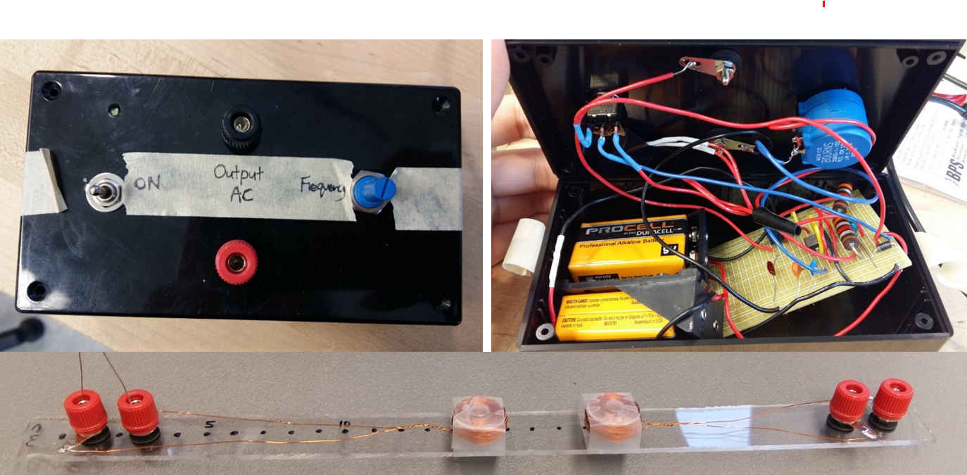
08/11/2018 at 21:28 • 0 commentsThe portable generator was able to induce a sine wave on the secondary coil for frequency range of 55-194 kHz, which achieved the main goal of the project.
However, the circuit seem to get unstable due to kickback of the coils when Potentiometer2 (filter) became small, with voltage spikes as large as 21 V peak to peak! This would cause the circuit to ‘crash’ and need to be reset. Thus for safety reasons the ‘shaping’ potentiometer (filter) is hidden within the box, not for user control.Future upgrades could increase the stability of the circuit with an op-amp buffer, or an added transistor to amplify the current to drive the coils. A second potentiometer can also be added to increase the range of lower frequencies of the oscillating circuit to achieve the conventional 60 Hz.
If possible, a step-up transformer to can also be added to raise the output to 120V or 240V, which will greatly expand the portable unit’s usability.
i think it'd also be interesting to figure out the output current, and maybe test it out on other small AC-needing devices (and watch them die hahahahah).
-
Testing with a Stubborn Load (EM Coils)
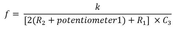
08/11/2018 at 21:24 • 2 commentsThe Make book suggested that for 555 oscillating circuits similar to this, the frequency can be calculated with
I attempted to achieve greater frequencies by reducing R1 and R2, but the high current caused the resistors and chip to be hot. The constant k depends on the other components in the circuit. If I define k = 1440 as given in the book’s example, my maximum frequency should be around 260 MHz. However, the measured range of oscillator was only 55-194 kHz. This big difference is probably due to the k value due to other component’s differences.
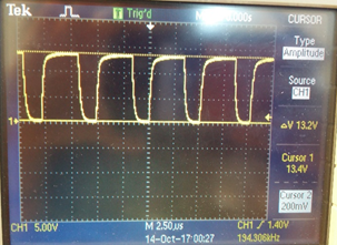
The variable RC filter was controlled by potentiometer2 (P2). The resistance on P2 was varied to suit the frequency and smooth out the square waves.
The image on top shows the output without the load, and the image on the bottom shows the output when the load is connected. Varying the frequency (with P2) revealed all sorts of curve shapes across the primary coil, and this ‘spiky’ voltage curve induced the best results on the secondary coil
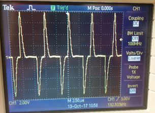
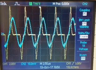
The blue curve on top shows the voltage across the secondary (receiver) coil with lots of higher frequency oscillations. The blue curve on the bottom shows a nice sine wave with the higher frequencies filtered out. Based on the RC equation below a 1pF capacitor was needed for a frequency of around 192 kHz.
f = 1/(2*pi*R*C)When the frequency is greatly varied, however, another capacitor will need to be used to filter out the ‘extra’ higher frequency waves. So that's a problem with varying frequencies hmmm.
-
Circuit Design
08/11/2018 at 21:17 • 0 commentsSince this unit is to be used for field work, it needs to be portable (battery powered). The parts should be cheap and easily available. For a big enough reading induced on the pickup coil (Vpp > 10 mV), a big enough voltage supplied to primary coil is needed to drive and pull enough current through the primary coil. Lastly, the unit must be able to vary oscillating high frequencies (1 kHz – 1000 kHz) to suit other factors such as terrain conductivity , and coil spacing.
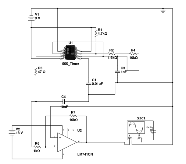
I considered a transistor, op amp, and 555 timer oscillator circuit. The specific transistors required for an oscillating circuit were not immediately available, and the frequency is not as easily changeable, so I did not pick the transistor circuit. The Op-amp (LM741CN) did not work well with high frequencies, which was observed on the breadboard prototype and verified in the datasheet. Furthermore it needed more than two 9V batteries which would make the system more bulky.
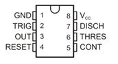
Thus I chose the NE555P timer which would run in astable mode, as it can generate a very high frequency which is easily controllable by pin 5.
The unknown inductance of the coils must be very large, as there was severe kickback to the circuit. Adding the Op-Amp protected the 555 oscillator (retaining square wave) and provided a gain of ~1.75, but the LM741CN could not power up with two 9V batteries, and could not drive sufficient current through the coil (worse than without the op amp). Since the cons outweigh the pros, I removed the op-amp and increased the input to 555 to 19V so that output is higher (previously Vpp ~ 5V).
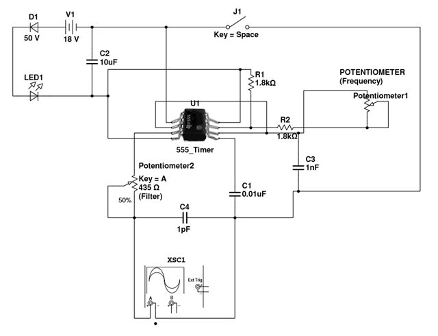
Since the NE555P max input voltage is 16V according to the datasheet, I used a diode and LED to reduce the input voltage.
Palm-sized AC Generator
Portable 9V battery powered DC to AC converter with variable frequency
 The blue curve on top shows the voltage across the secondary (receiver) coil with lots of higher frequency oscillations. The blue curve on the bottom shows a nice sine wave with the higher frequencies filtered out. Based on the RC equation below a 1pF capacitor was needed for a frequency of around 192 kHz.