 sfowen
-
1Download files
Download following files and store on your computer:
1) PhotBox_v1d_sch1_2018-07-24.zip
2) FibPhotBox_v3_lid.stl
3) FibPhotBox_v3_box.stl
4) fibPhotBox6_LPC1768.bin
-
2Order PCB
Navigate to:
https://www.seeedstudio.com/fusion_pcb.html
Click "Add Gerber Files"Navigate to and select "PhotBox_v1d_sch1_2018-07-24.zip"
Click "OK"Make sure PCB Dimensions are 100mm x 160mm
Select desired color
All other default options should be OK
-
3Order commercial components
Order all other commercially available components off of parts list from Digikey,
McMaster-Carr and National Instruments
-
4Order Enclosure
Order enclosure from your favorite 3D printing service. Note enclosure box and lid are stored in separate ".stl" files
-
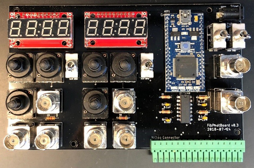
5Solder components
Start with smallest (shortest) components first, then work towards tallest so that board can be flipped-over at each step to solder components in place without them dropping out.
Suggested soldering order
- Resistors (no orientation)
- Op-Amp (Notch on Op-Amp should point towards the MBED)
- Capacitors (no orientation)
- NI-DAQ connector (connector should point out over bottom edge of board)
- Power Supply
- MBED Microcontroller (USB connector should point towards top edge of board)
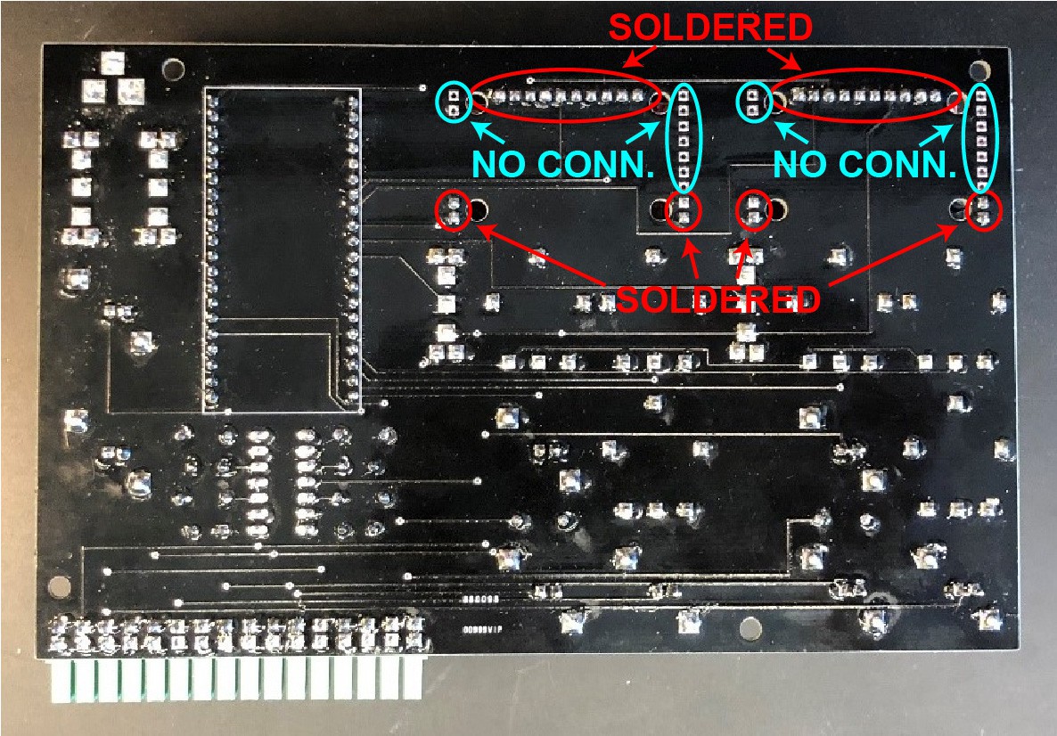
- Displays
- Place displays into spacer pins (don't solder yet)
- Colored dots on side of indicate color of display
- Place spacer pins into PCB
- Not
all spacer pins need to be connected (see below). I solder only pins on top row (for electrical connections) and two pins in each bottom corner for structural stability. Remaining pins on edges can be skipped
- Solder spacer pins into displays from front face
- Flip PCB over and solder spacer pins into PCB
- Switches (no orientation)
- BNCs
- Potentiometers
![]()
![]()
-
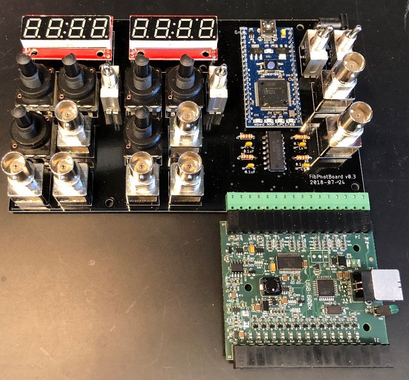
6Remove NI-DAQ card from enclosure
Undo the three screws on the plastic enclosure of the NI-DAQ USB-6009 card using a phillips head screwdriver. Attach the card to the PCB as shown, with the USB connector pointing to the right as shown.
![]()
-
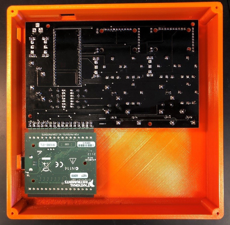
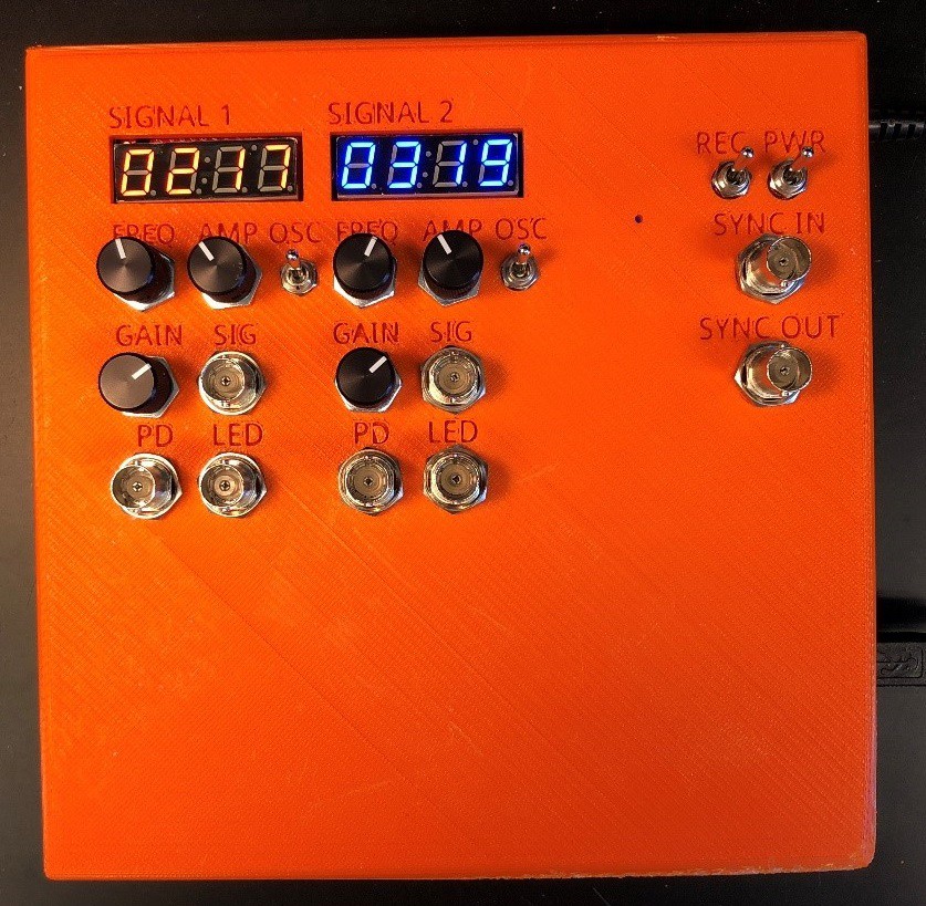
7Put the PCB into the enclosure
- Remove all nuts and washers from BNCs, switches and potentiometers
- Place the PCB into the enclosure and line up screws
- Use self-tapping screws to attach PCB and NI-DAQ USB-6009 to stand-offs inside the enclosure
- Attach nuts to all connectors on front face to affix components in place
- Attach knobs to potentiometers
![]()
![]()
-
8Load firmware onto MBED microcontroller
- Connect MBED microcontroller to computer through USB (it will show up as a thumb drive).
- Copy the binary file "fibPhotBox6_LPC1768.bin" onto the MBED
- With the box powered on, reset the MBED by inserting a paper clip or fine hex wrench through the small hole on the front of the enclosure to press the reset button
-
9Set up the NI-DAQ Card
Install the NI-DAQmx software
National Instruments NI-DAQmx software and drivers
Connect the NI-DAQ USB-6009 to the computer with USB cable and allow computer to install drivers
-
10Set up the DAQ software
Note, the NI-DAQ USB-6009 digitizer will interface easily with a wide variety of software, including Matlab. Instructions and code provided here describe use with the freely available Strathclyde WinEDR digital recording software
- Download and install Strathclyde WinEDR:
Strathclyde WinEDR - Make sure NI-DAQ USB-6009 is connected to the computer
- Open WinEDR
- Navigate to Setup-->Laborator Interface Setup
- Select "National Instruments (NIDAQ-MX)"
- Set "A/D Input" to "Single Ended (RSE)"
- Select "USB-6009 (8ch 13bit +-10V ADC, 2ch. 12bit +-5V DAC"
- Click "OK"
- Naviate to "Record-->Record to disk"
- Set "No. channels" to "8"
- Set "Sampling Interval" to 2ms
- Set "No. sweeps" and "Duration" as desired. I always set "No. sweeps" to "1", and "Duration" to a time much longer than my recording session will run (e.g. 36000 sec).
- Download and install Strathclyde WinEDR:
PhotometryBox
This microcontroller-based system simplifies control electronics for optical fiber-based fluorescence measurements in neuroscience.
Discussions
Become a Hackaday.io Member
Create an account to leave a comment. Already have an account? Log In.
Hello there! I'm currently using the PhotometryBox for my experiment!
However, I'm struggling with the synchronization of the module with a behavioral camera.
It would be ideal for me to have the camera acquisition triggered by the SyncOut channel. Still, the TTLs that come from this channel have a fixed frequency (1second). Is there a way to modify the frequency?
Thanks for the good work and the incredible piece of hardware!
Best,
Marco
Are you sure? yes | no
Matlab post-hoc analysis scripts have been updated to correct how the cut-off frequency for the final low-pass filtering of the processed data is determined
Are you sure? yes | no