-
Works before this
08/18/2018 at 11:02 • 0 commentsUsing a motor as a rotary encoder is obviously not new. You can read the previous log entry to see how I was inspired.
But every attempt I saw so far used the motor (BLDC, PMSM or hybrid stepper) as a generator, and measured the phase voltage looking for a transition edge or keeping track of amplified levels. The main problem with this is, if the rotation speed is too low, the output level is also low and movement is not detected. To counter that, amplifiers are often used. But that won't solve the problem completely and at one point introduces a new one: noise.
My approach is different. I use the coils in the motor as coupled inductors and the rotor changes the coupling ratio. This isn't a new thing either, just google "inductive encoder". Even more, I'm pretty sure I'm not the first person to try this, but I didn't find a widely public writing. Meanwhile, I saw the reactions to the previous projects, many liked them despite the drawbacks.
That's why I do this, I try to give a better solution.
-
First try
08/18/2018 at 10:14 • 0 commentsTo be honest, this isn't the absolute first. Last year, when I watched Great Scott's video I had the idea for this, and a little later I tested it. I just set up an MCU to put out a PWM signal, hooked it up to a makeshift half-bridge (basically just an amplifier), pulled out a motor off my scrapheap and connected all. Motor phase 1 to ground, phase 2 to PWM output, phase 3 floating. Phase 2 and 3 monitored by my oscilloscope's two channels.
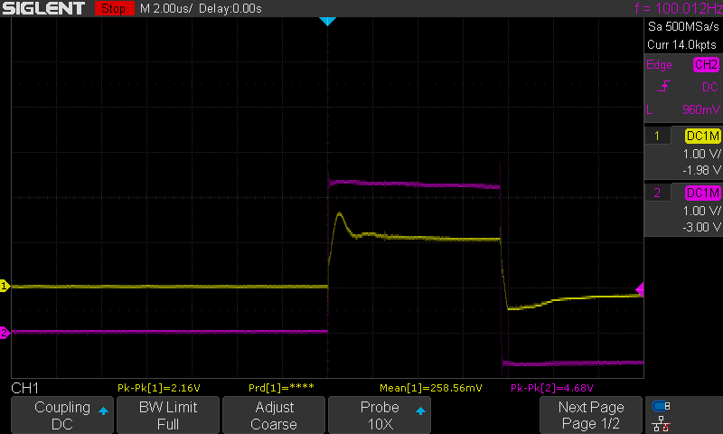
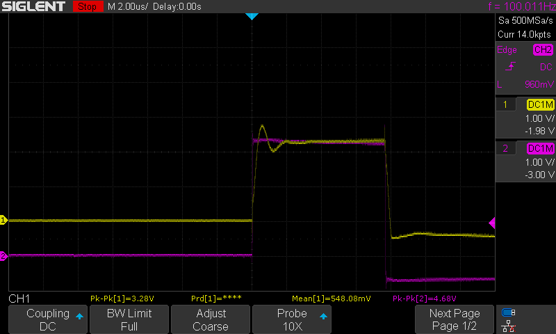
The result was something like this:
![]()
![]()
The driving signal CH2, and the floating lead CH1. Between taking these two screenshots I turned the rotor a little, but it was not moving when I took the pictures.
Small 3 phase motors have 3 or 4 contacts, depending on coil configuration. Mine has 3 and probably a star connection. If you run current through two leads, you drive two coils in series. The third lead is also connected to the star point through the third coil. If the current is DC, the coils act as a simple voltage divider, the 3rd lead has half the driving voltage. If the current is AC, there is also some electromagnetic coupling among the coils and it includes the rotor. If the rotor is not in a central position between the coils, it somehow bends or switches the flux, the voltage will be uneven, and easily detectable.
Motor as Encoder
Inspired by the attempts of other people around the Interwebs, I use a motor as a rotary encoder, but with a different approach.