-
High speed? Not yet.
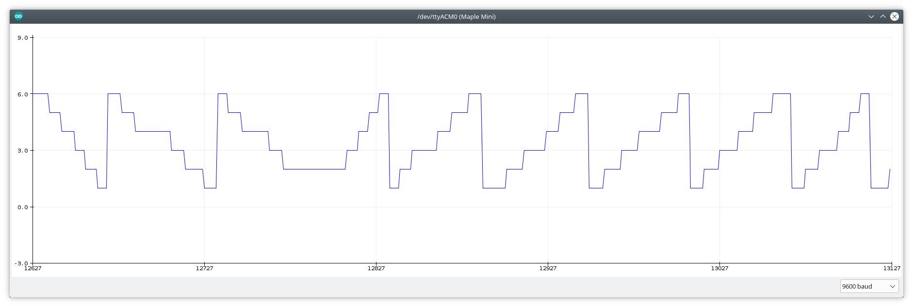
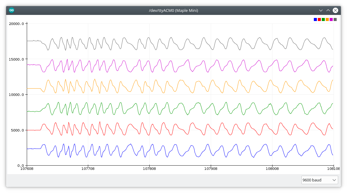
09/14/2018 at 13:38 • 0 commentsI didn't post this screenshot previously (didn't seem important), but it shows the problem with high speed.
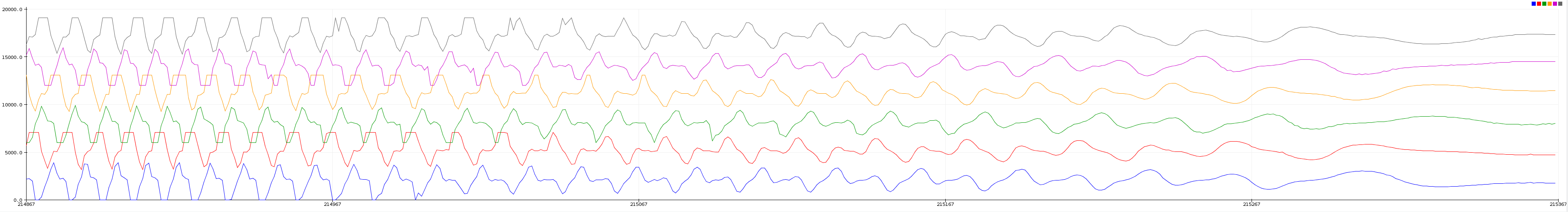
![]() I set higher frequency scanning and spun the thing by hand with a speed that's unusually fast for a knob. The graph shows how the rotor slows down after that. Note how the pattern is changing by time. Not just amplitude but the shape too. The EMF distorts the signal so much, my simple algorithm can't recognize the changes. That's why I mentioned in the project details that an advanced method is needed for this case.
I set higher frequency scanning and spun the thing by hand with a speed that's unusually fast for a knob. The graph shows how the rotor slows down after that. Note how the pattern is changing by time. Not just amplitude but the shape too. The EMF distorts the signal so much, my simple algorithm can't recognize the changes. That's why I mentioned in the project details that an advanced method is needed for this case. -
Video
08/19/2018 at 22:07 • 0 commentsHint: turn on CC.
-
Another spin
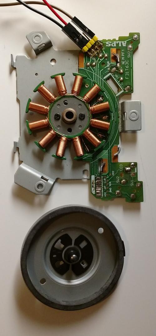
08/19/2018 at 18:01 • 0 commentsI tried this motor (salvaged from a floppy drive):
![]()
It almost worked. Tuning was a nightmare. Measurements were noisy, and levels were almost indistinguishable. It jumped back and forth, sometimes started to rotate indefinitely. For a few steps, it worked, but wasn't as nice or reliable as the HDD motor.
-
Are we there yet?
08/19/2018 at 10:25 • 0 commentsWell, almost. It is working. Writes the position to serial. It can be overwritten via serial, the motor will turn to that position. Haptic feedback can be turned off. Still misses steps sometimes, but it is rare, and I think this won't be an issue if not only basic Arduino functions are used, but some advanced methods.
![]()
The code could be nicer, I have to work on that. I'll upload the current, ugly version anyway. For the impatient.
Some schematics would be great too. I'll do that later.
-
When in doubt, draw lines
08/19/2018 at 07:50 • 0 commentsSo, my sophisticated method for analyzing the results was to draw lines over the screenshots in paint. And on paper with a pencil. :-) Just to understand the data well enough.
Conclusions:
- The sensor data comes in 3 pairs. Mirrored to each other. Simply because I measure all sets twice, with opposite polarity. We can select 3 to work with in operation.
- The period of the sensed signal is half of the drive signal. The motor has 6 steps in one magnetic cycle (my motor has 4 cycles, 30 steps/revolution) and the sensed signal repeats after 3 steps. That can be a problem with haptic feedback. When you switch it on the first time, the controller doesn't know in which half of the magnetic cycle the motor is. That can cause a bigger than normal jump of the rotor, and missed or false steps. Not catastrophic, but inconvenient. It can be moderated if the high current drive is ramped up with PWM.
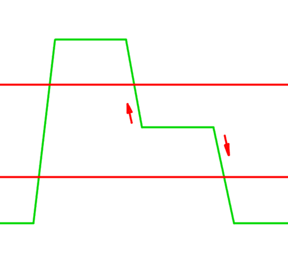
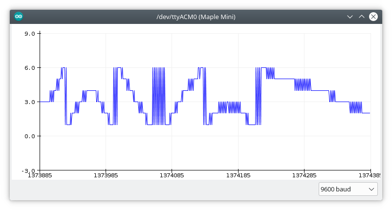
- In my opinion, the easiest way to detect a movement is to store the last step, and measure one signal of the selected 3.
In every "clean" step, one of them is at center position, in my case that means an ADC result of 2000 - 2150. The high position can reach 2800, low 1300. (Due to laziness, I only noted one channel.) selecting threshold values is easy. If that channel is measured, which should be centered, and it goes up, that means a step in one direction, down is the other.![]()
-
Light at the end of the tunnel
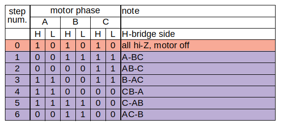
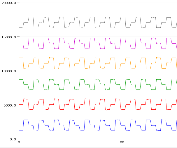
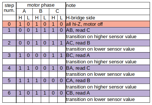
08/18/2018 at 19:37 • 0 commentsI just realized, the way I drove the motor for scanning doesn't match up with the nice and clean position signals. This does:
![]()
![]()
One step closer.
-
Second run
08/18/2018 at 17:56 • 0 commentsI hope you see it. I surely don't.
#define PAH PB7 //phase A high side #define PAL PB14 //phase A low side #define PBH PB6 //phase B high side #define PBL PB13 //phase B low side #define PCH PB5 //phase C high side #define PCL PB12 //phase C low side #define PAF PA0 //phase A feedback #define PBF PA1 //phase B feedback #define PCF PA2 //phase C feedback int fbbuf; void scan(){ //AB digitalWrite(PAL, LOW); digitalWrite(PBH, HIGH); digitalWrite(PBL, HIGH); digitalWrite(PCH, HIGH); digitalWrite(PCL, LOW); digitalWrite(PAH, LOW); //put last to reduce adc delay fbbuf = analogRead(PCF); //read C digitalWrite(PAH, HIGH); //switch off Serial.print(fbbuf); Serial.print(' '); //AC digitalWrite(PAL, LOW); digitalWrite(PBH, HIGH); digitalWrite(PBL, LOW); digitalWrite(PCH, HIGH); digitalWrite(PCL, HIGH); digitalWrite(PAH, LOW); //put last to reduce adc delay fbbuf = analogRead(PBF); //read B digitalWrite(PAH, HIGH); //switch off Serial.print(fbbuf+3000); Serial.print(' '); //BC digitalWrite(PAH, HIGH); digitalWrite(PAL, LOW); digitalWrite(PBH, LOW); digitalWrite(PBL, LOW); digitalWrite(PCH, HIGH); digitalWrite(PCL, HIGH); fbbuf = analogRead(PAF); //read A digitalWrite(PBH, HIGH); //switch off Serial.print(fbbuf+6000); Serial.print(' '); //BA digitalWrite(PAH, HIGH); delay(1); //measuremenet was noisy digitalWrite(PAL, HIGH); digitalWrite(PBH, LOW); digitalWrite(PBL, LOW); digitalWrite(PCH, HIGH); digitalWrite(PCL, LOW); fbbuf = analogRead(PCF); //read C digitalWrite(PBH, HIGH); //switch off Serial.print(fbbuf+9000); Serial.print(' '); //CA digitalWrite(PAH, HIGH); digitalWrite(PAL, HIGH); digitalWrite(PBH, HIGH); digitalWrite(PBL, LOW); digitalWrite(PCH, LOW); digitalWrite(PCL, LOW); fbbuf = analogRead(PBF); //read B digitalWrite(PCH, HIGH); //switch off Serial.print(fbbuf+12000); Serial.print(' '); //CB digitalWrite(PAH, HIGH); digitalWrite(PAL, LOW); digitalWrite(PBH, HIGH); digitalWrite(PBL, HIGH); digitalWrite(PCH, LOW); digitalWrite(PCL, LOW); fbbuf = analogRead(PAF); //read A digitalWrite(PCH, HIGH); //switch off Serial.print(fbbuf+15000); Serial.print(' '); } void setup() { pinMode(PAH, OUTPUT); pinMode(PAL, OUTPUT); pinMode(PBH, OUTPUT); pinMode(PBL, OUTPUT); pinMode(PCH, OUTPUT); pinMode(PCL, OUTPUT); pinMode(PAF, INPUT_ANALOG); pinMode(PBF, INPUT_ANALOG); pinMode(PCF, INPUT_ANALOG); } void loop() { delay(10); scan(); Serial.print('\n'); }![]()
-
First jump, first fall
08/18/2018 at 17:08 • 0 commentsSo, after the last successful step, I took a big leap... and then failed.
OK, there was an intermittent one, I determined the motor's coil sequence and made it spin. Also that, what kind of change should I look for.
![]()
Then the logical step and the seemingly easiest way was to scan with short current pulses for movement, update the tracking variable, scan accordingly again. Why is this logical? Because implementing haptic feedback is just lengthening the pulse. But no, doesn't work. "Maybe if I make it longer, so it jumps into the next position." No.
The problem is, if I wait too long, it skips steps. If I wait too short, it oscillates mid-steps.
![]()
You can take a look at the code where I gave up this side.
-
Software so far
08/18/2018 at 11:57 • 0 commentsSome basic definitions and a single phase test. PoC.
/*   3 half bridges made of complementary FETs, all gates are driven by MCU
 *   high sides are off when corresponding MCU pins are high
 *   low sides are off when corresponding MCU pins are low
 *   3 phase motor connected to half bridge outputs
 *   these outputs are also connected to MCU analog pins to provide voltage feedback
 */


#define PAH PB7   //phase A high side
#define PAL PB14  //phase A low side
#define PBH PB6   //phase B high side
#define PBL PB13  //phase B low side
#define PCH PB5   //phase C high side
#define PCL PB12  //phase C low side
#define PAF PA0   //phase A feedback
#define PBF PA1   //phase B feedback
#define PCF PA2   //phase C feedback

int fba, fbb, fbc;

void setup() {
  pinMode(PAH, OUTPUT);
  pinMode(PAL, OUTPUT);
  pinMode(PBH, OUTPUT);
  pinMode(PBL, OUTPUT);
  pinMode(PCH, OUTPUT);
  pinMode(PCL, OUTPUT);
  pinMode(PAF, INPUT_ANALOG);
  pinMode(PBF, INPUT_ANALOG);
  pinMode(PCF, INPUT_ANALOG);
  //neutral, off state:
  digitalWrite(PAH, HIGH);
  digitalWrite(PAL, LOW);
  digitalWrite(PBH, HIGH);
  digitalWrite(PBL, LOW);
  digitalWrite(PCH, HIGH);
  digitalWrite(PCL, LOW);
}

void loop() {

  digitalWrite(PAL, HIGH);  //drive phase A low (turn on low side transistor)
  digitalWrite(PBH, LOW);   //drive phase B high (turn on high side transistor)
  fba = analogRead(PCF);     //read feedback voltage
  //delay(1);
  digitalWrite(PBH, HIGH);  //drive phase B low (turn off high side transistor)
  delay(10);

  Serial.println(fba);
}
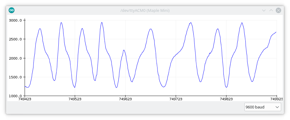
baseline, somewhat center position 
I turned the rotor a little and then left it there As seen on the first graph, some noise is present when the rotor is not moving but, as you can see on the second one, the signal-noise ratio is very good. The signal slope is not even. Some regions have steeper slopes than others. On the second graph, the section from the start to the valley bottom represents an almost constant velocity. The varying slope is the product of the physical construction of the motor. Here I tried to spin it slowly but evenly with a sudden direction change at around 749623:
![]()
If you change the delays in the code, you can change the sampling frequency and the on-off ratio. With more on-time the rotor wants to stay in a certain position. That is basically a method for haptic feedback.
-
Hardware setup
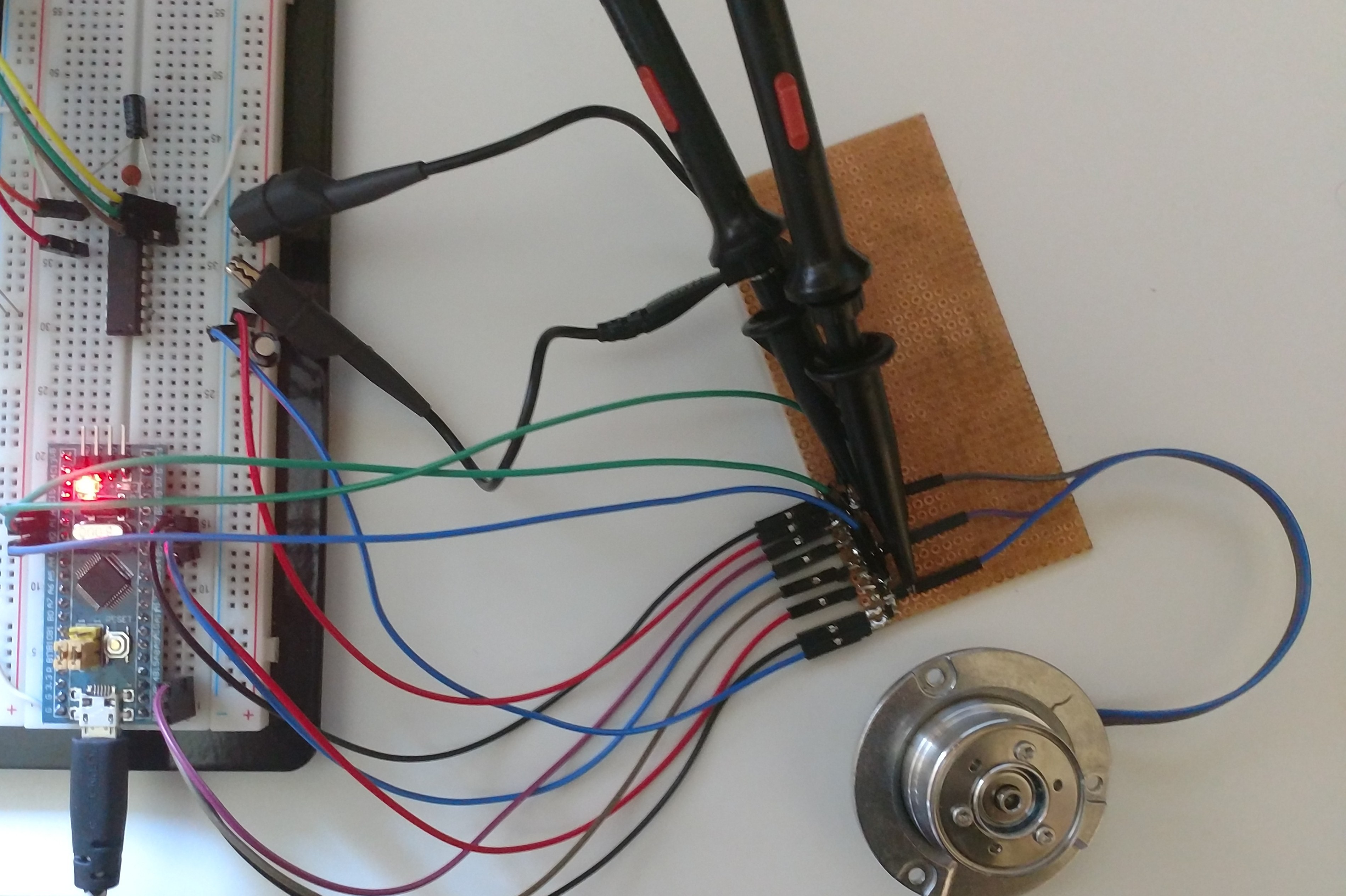
08/18/2018 at 11:26 • 0 commentsA few days ago I received my first Arduino compatible boards. I'm not a fan of Arduino, but that's what many people like and almost everyone have. These are cheapo "Blue Pill" STM32 based boards. The first thing I did was to flash them with STM32duino.
Previously, I made a triple half bridge from SMD FETs. Thisis ugly and underpowered, but works. (Theoretically, amplification is not needed, if the microcontroller has high current pins.)
![]()
(Please ignore the DIP chip in the breadboard, not related, but I was lazy to take it out.)
6 digital outputs are used, because we need to drive the high and low side transistors separately, the phase which is not driven should be floating, hi-Z mode is necessary.
3 analog inputs are used as feedback. The phase voltages are measured with them.
Currently everything goes from 3.3V. The chip is powered from USB, but there is a separate power supply for the motor. The analog inputs can withstand 3.3V only. If the motor's supply is higher than that, voltage dividers are needed on the feedback lines to protect the MCU. If you want to use the encoder passively, 3.3 is enough, but for haptic feedback a higher voltage is probably needed.
Motor as Encoder
Inspired by the attempts of other people around the Interwebs, I use a motor as a rotary encoder, but with a different approach.
 I set higher frequency scanning and spun the thing by hand with a speed that's unusually fast for a knob. The graph shows how the rotor slows down after that. Note how the pattern is changing by time. Not just amplitude but the shape too. The EMF distorts the signal so much, my simple algorithm can't recognize the changes. That's why I mentioned in the project details that an advanced method is needed for this case.