Introduction
Small 3 phase motors can be used as a set of coupled inductors. If you run current through two leads, you drive two coils in series. The third lead is also connected to the star point through the third coil. If the current is DC, the coils act as a simple voltage divider, the 3rd lead has half the driving voltage. If the current is AC, there is also some electromagnetic coupling among the coils and it includes the rotor. If the rotor is not in a central position between the coils, it bends the flux, the voltage will be uneven, and easily detectable. Even with a common microcontroller.
What have I done?!
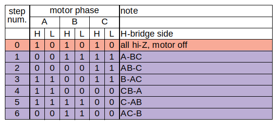
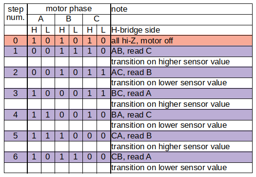
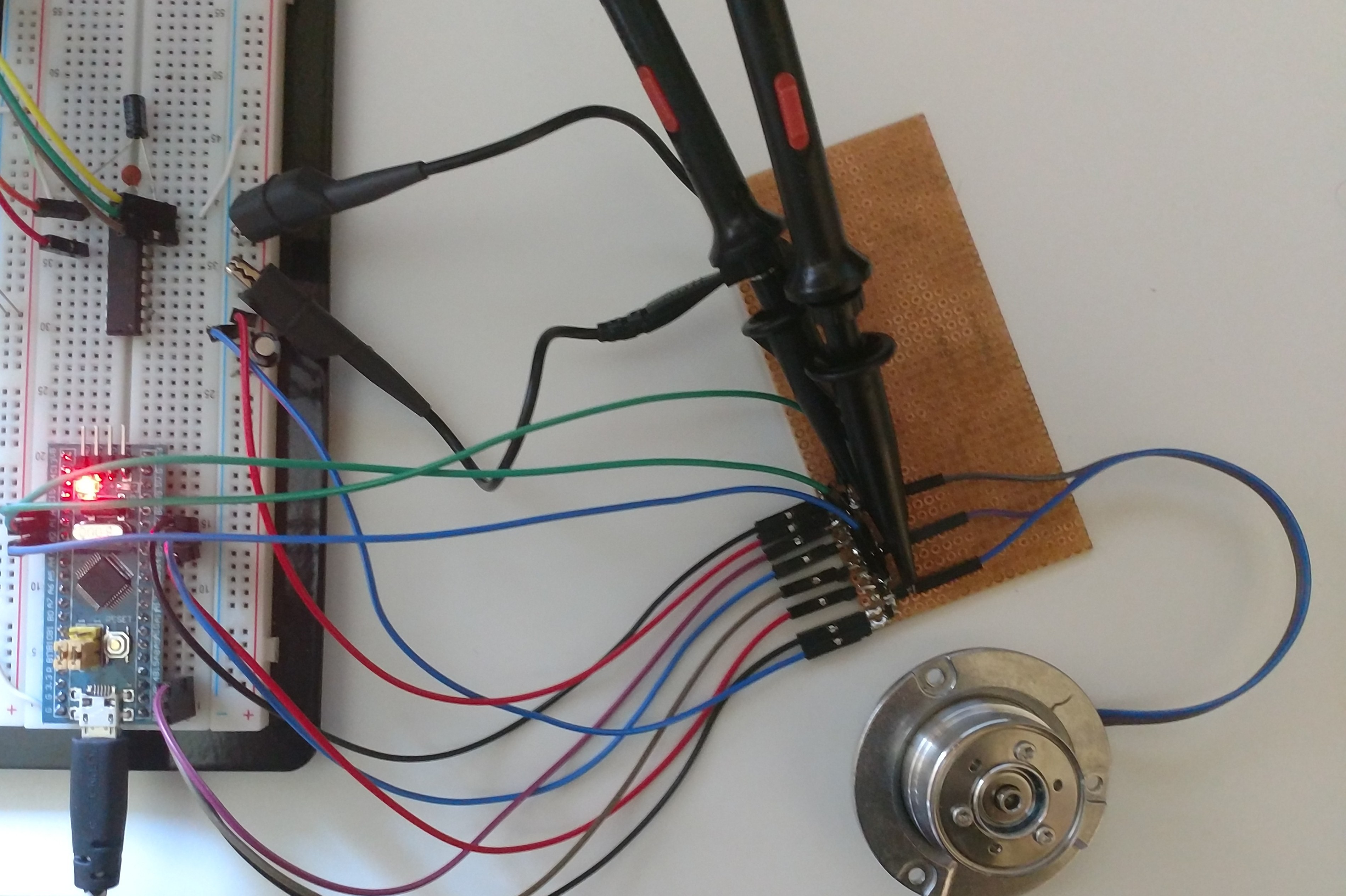
I used a Blue Pill (based on STM32F103 MCU) with STM32duino firmware. I connected it to a set of half bridges. It is needed to drive the motor with a higher current. The motor leads are connected to the these bridge outputs, and also to 3 Arduino ADCs. The inductive coupling and thus the angle of the rotor is indirectly measured with these. I set one selected half bridge to drive the motor lead to low level (ground), another one to high (power supply), and the third one to nothing (floating). Right after the voltage is applied to the coils, current rushes through, and on the floating lead a voltage is measured. Ideally, the measurement is done in a few microseconds, and precisely timed for repeatability.
The 3 phases can be measured is 6 combinations, as 3 pairs. The pairs are inverted to each other because of the opposite polarity. Practically 3 channels can be selected for operation.
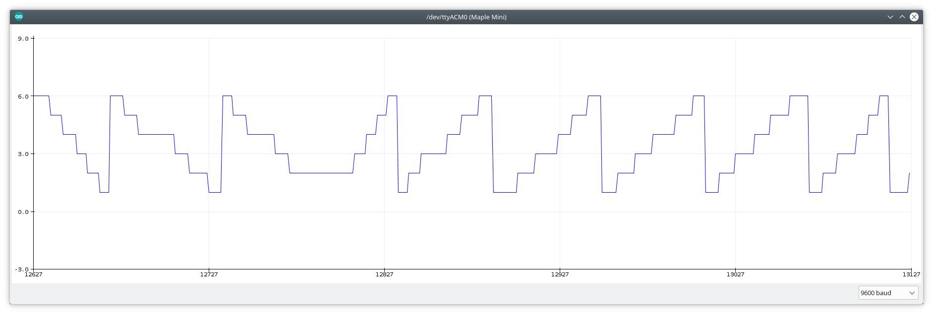
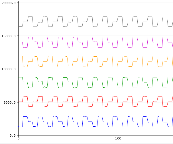
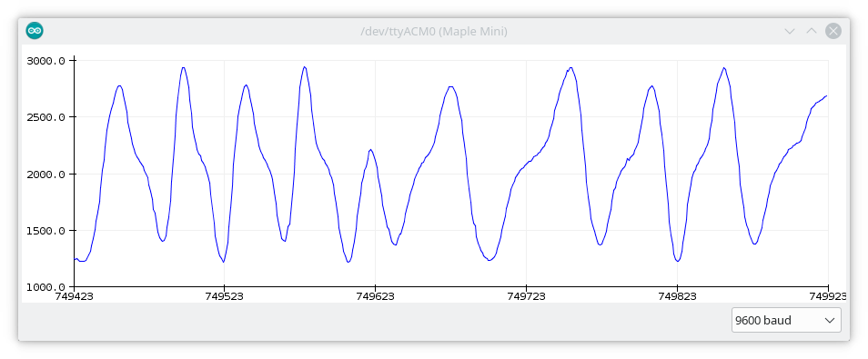
For each channel, an angle/signal plot can be drawn, and at the positions where it aligns with the motor's steps, well defined levels are present.
Once the correlation is mapped, detecting and tracking the movement is relatively easy.
Implementing haptic feedback is straightforward. Just drive the motor as you should anyway, interrupt it for a few milliseconds (microseconds with more optimized code) while you measure angle change, then continue. With certain driving schemes, interruption is not necessary at all.
The sample code I wrote is available on Github. It is a proof of concept, not application quality, but good enough to play around with it. It writes current position (step) on change and accepts commands via serial port. Position can be overwritten (rotor follows actively) and haptic feedback can be turned off (movement tracking continues).
Now what?
With this project I wanted to prove that, it can be done. And I did it. To reach a secondary goal, I'm making this documentation. Hopefully anybody, who is familiar with Arduino and electronics, can understand the principles and start developing a useful application with it.
Directions for further development (a few examples, out of the scope of this project):
- Better reliability, responsiveness and repeatability.
- Find better mapping and tracking methods. It can improve the attributes in previous line. And scanning at higher speeds may become possible.
- Autotuning. Connect any motor, send a command, wait a little, ready to go.
- Higher resolution. I selected a few convenient positions for steps, but this shows much more potential. Makes it possible to define positions not depending on motor configuration, but purely by software. E.g. uneven steps, changing steps on the fly as user wanders around a menu.
Footnote
Code, schematic and any other media content related to this project, which is created and published by me (besenyeim) is under Creative Commons Zero license. No Rights Reserved.
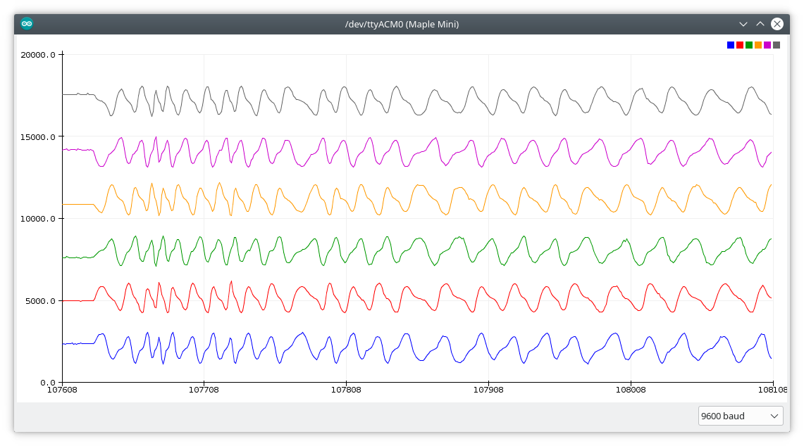
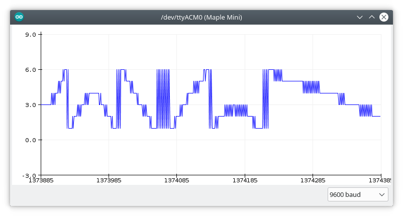
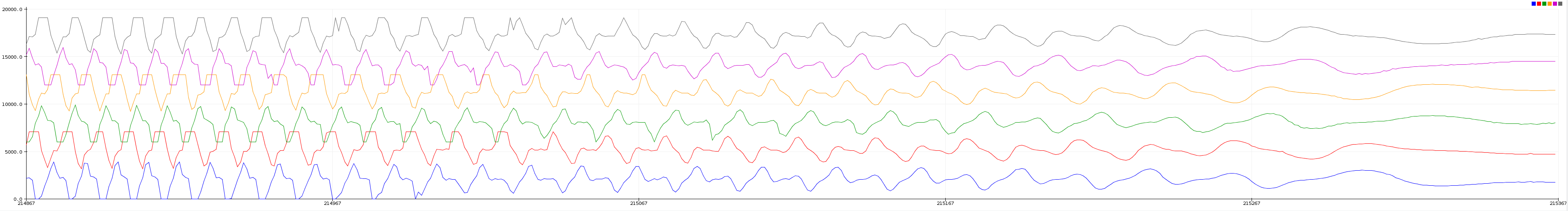 I set higher frequency scanning and spun the thing by hand with a speed that's unusually fast for a knob. The graph shows how the rotor slows down after that. Note how the pattern is changing by time. Not just amplitude but the shape too. The EMF distorts the signal so much, my simple algorithm can't recognize the changes. That's why I mentioned in the project details that an advanced method is needed for this case.
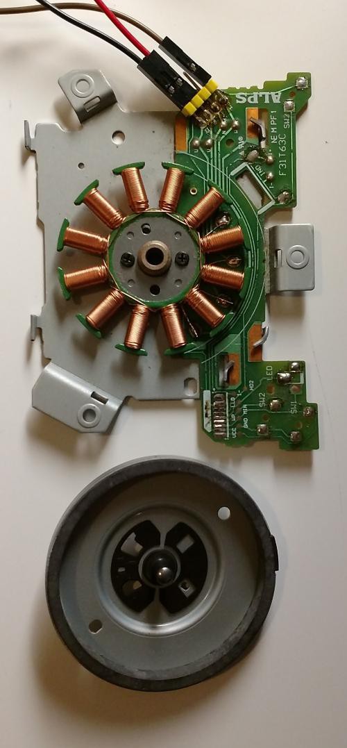


This is exciting for its possible use in a DIY Novint Falcon-type input device.