By popular demand (kinda), I developed a new receiver for the Redox codename Ultron project.
I thought this was needed because the Mitosis receiver is pretty hard to solder (I'm looking at you 1206 4.7k resistor array) and components are hard to find (at least at reasonable prices here in Europe. Stupid sexy Digikey international shipping fee).
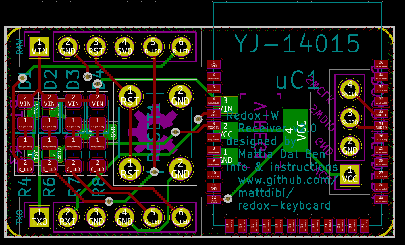
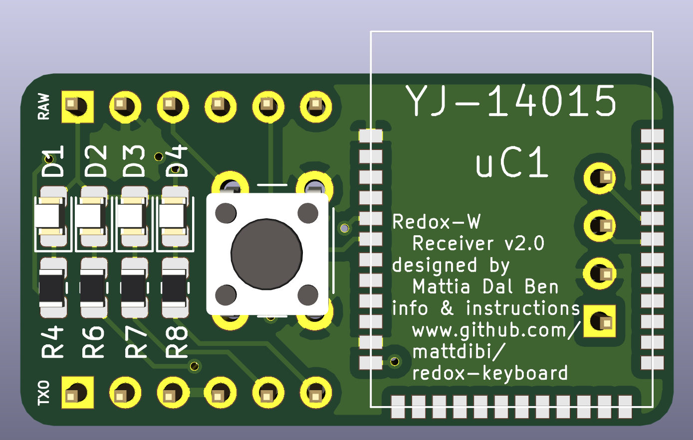
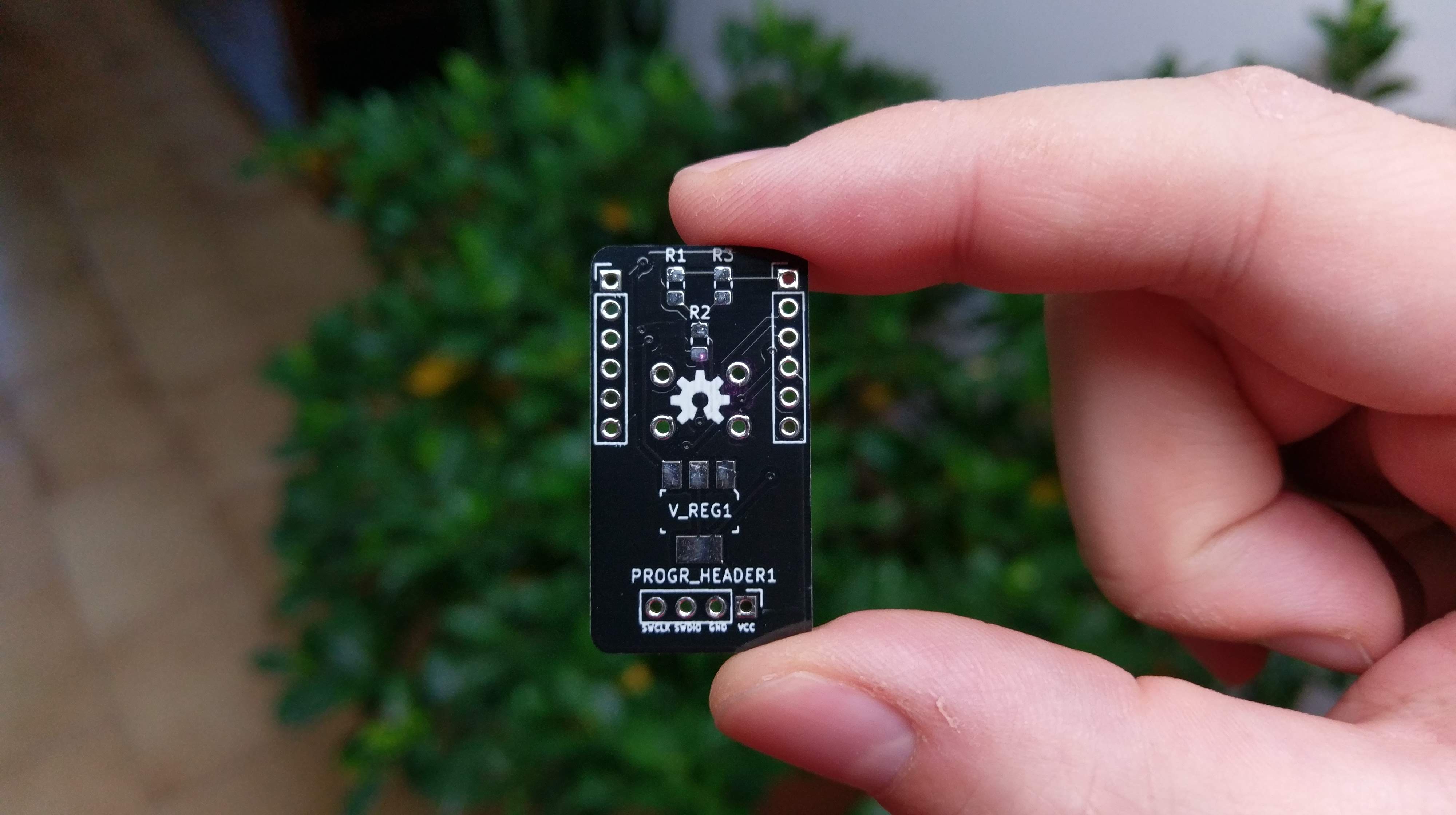
I then designed a receiver that uses only standard 0805 components, easy to solder and whose components can be easily found on eBay.
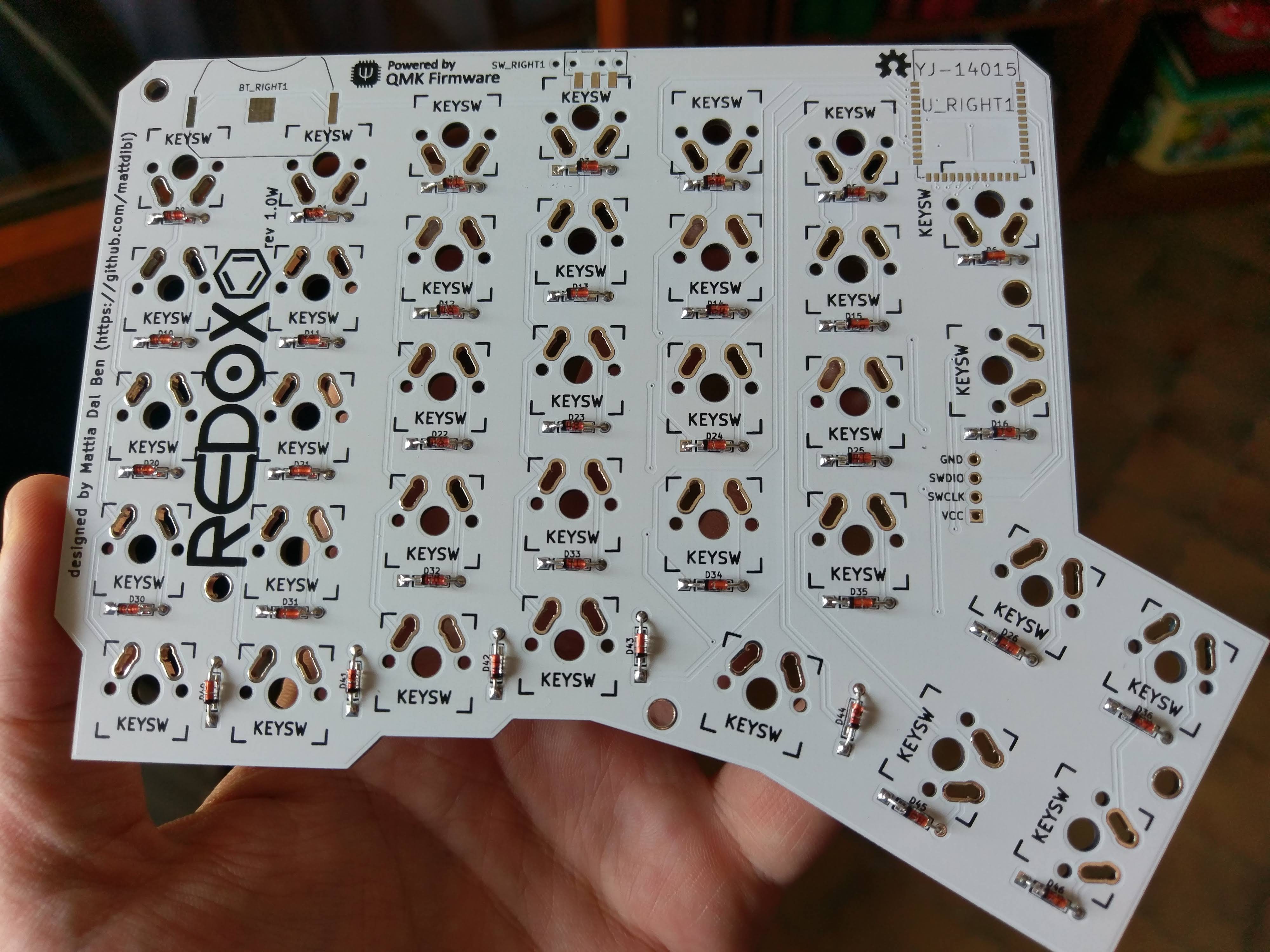
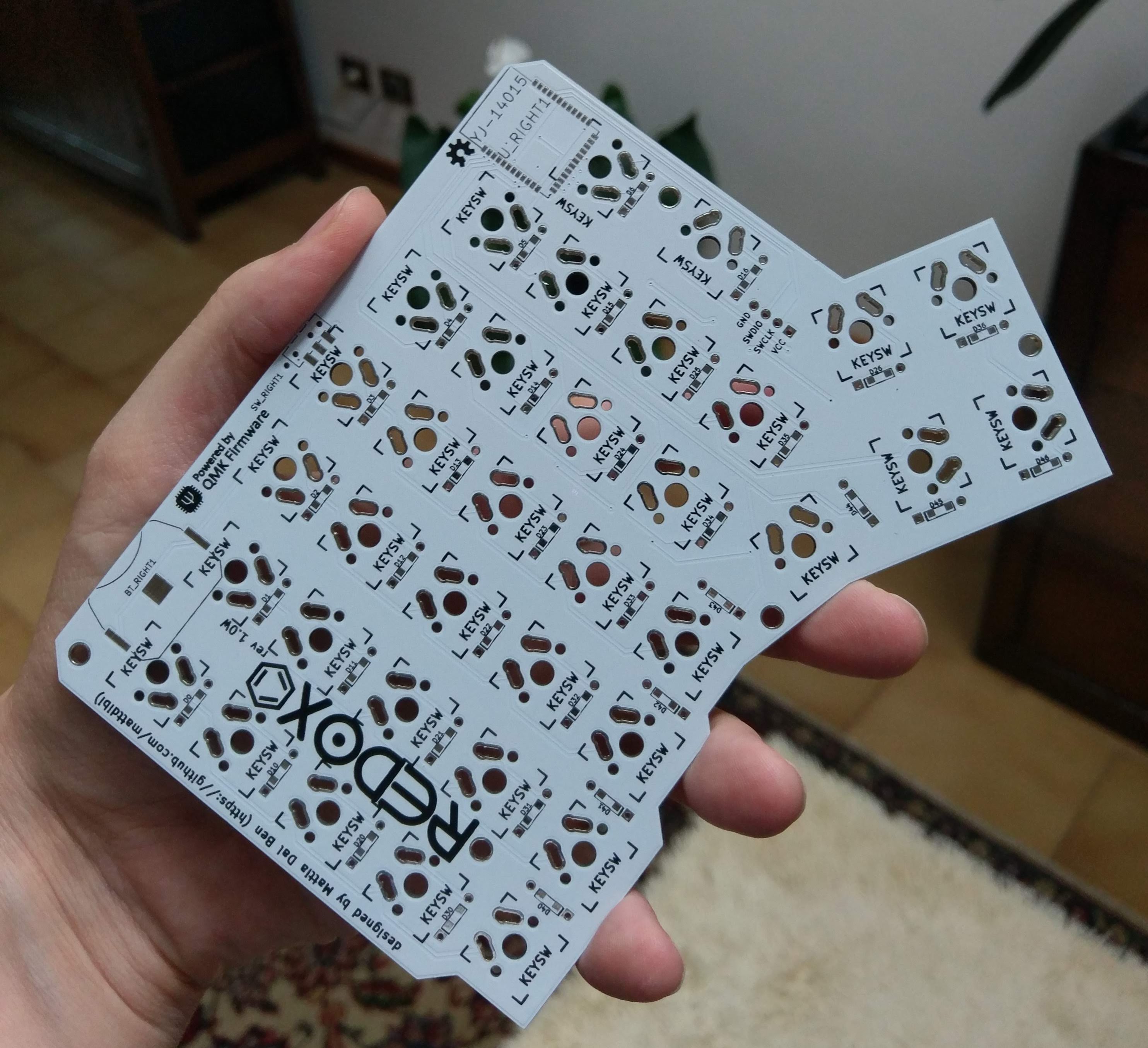
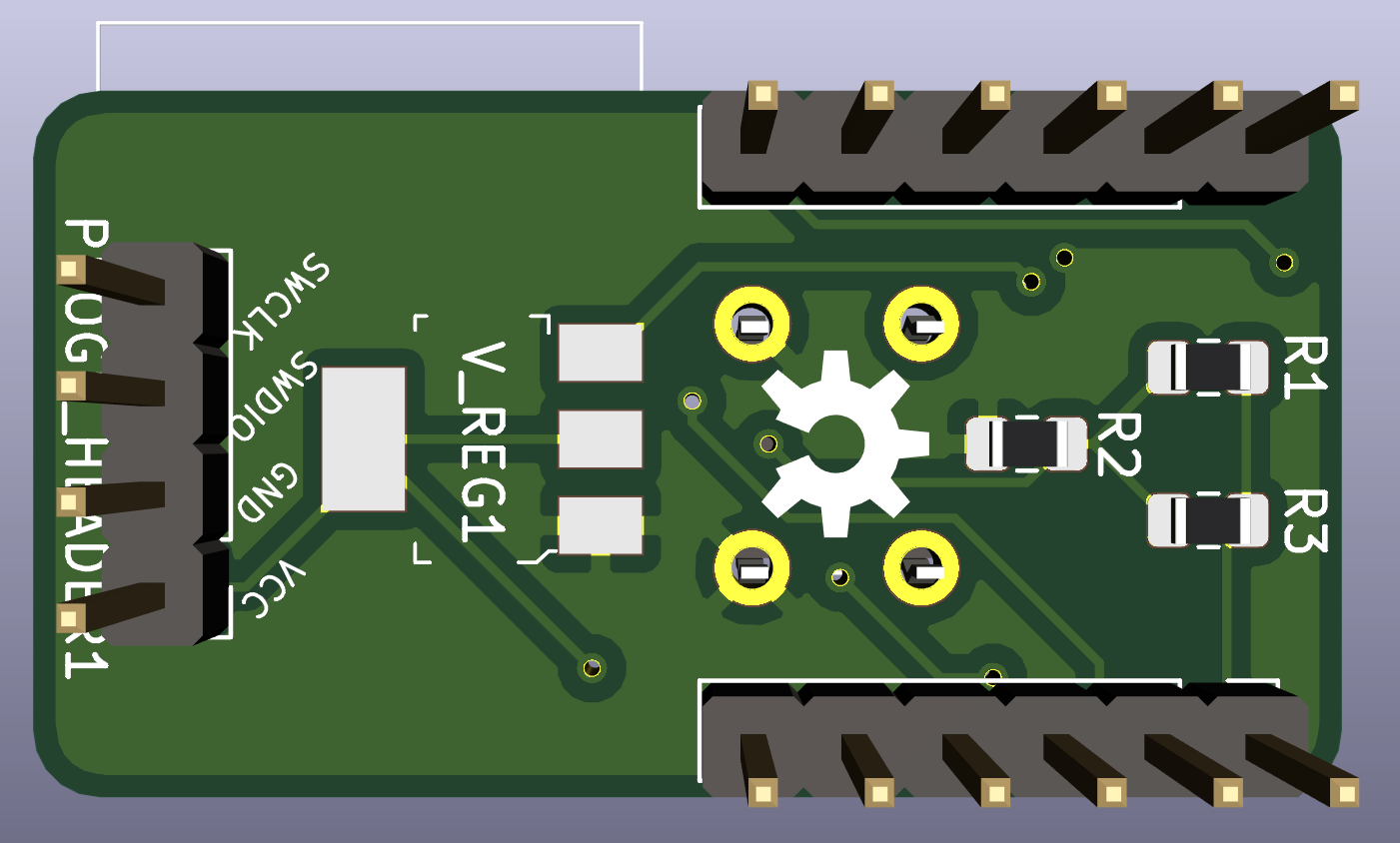
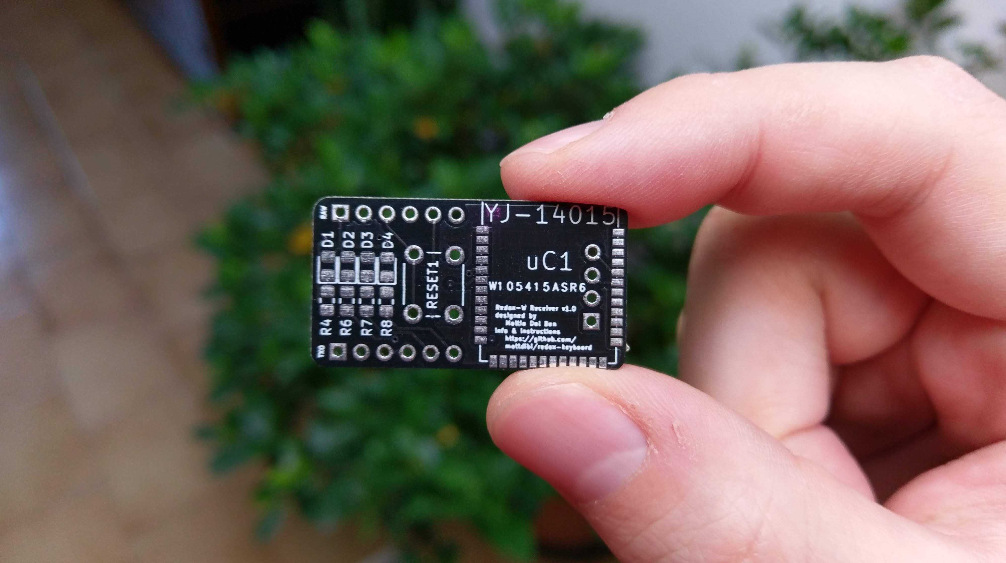
Here's the PCB I manufactured. Unfortunately the font wasn't really readable so I improved this in the v.2.0 of the receiver which is the one I got the rendering from.
Unfortunately I did not receive the MCUs yet so I had to improvise to test if everything is working.
Here's the latest measurements of the batteries' voltage:
Left hand voltage
Right hand voltage
30/09/2018
2.98
3.04
06/10/2018
2.98
2.99
13/10/2018
2.96
2.97
20/10/2018
2.97
2.98
27/10/2018
2.97
2.98
10/11/2018
2.98
2.98
2/12/2018
3.00
3.00
22/12/2018
2.98
2.97
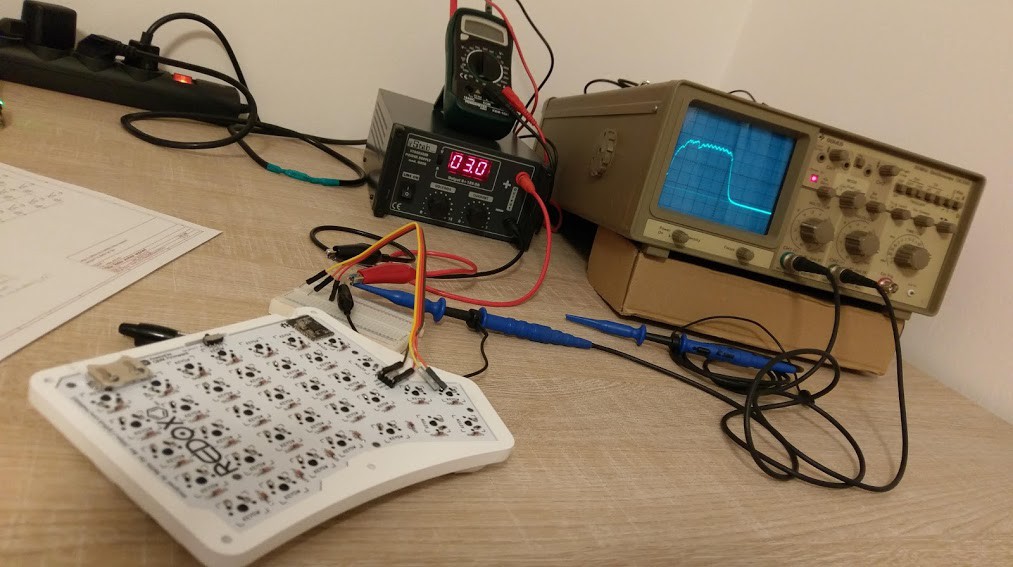
This was getting boring so I used this as an excuse to buy myself an oscilloscope for Christmas :D
Let's focus on the problem: I used a 10 Ohm shunt resistor to get the current used by the MCU of the transmitters. I put a pen under the keyboard to keep a key pressed and got the following:
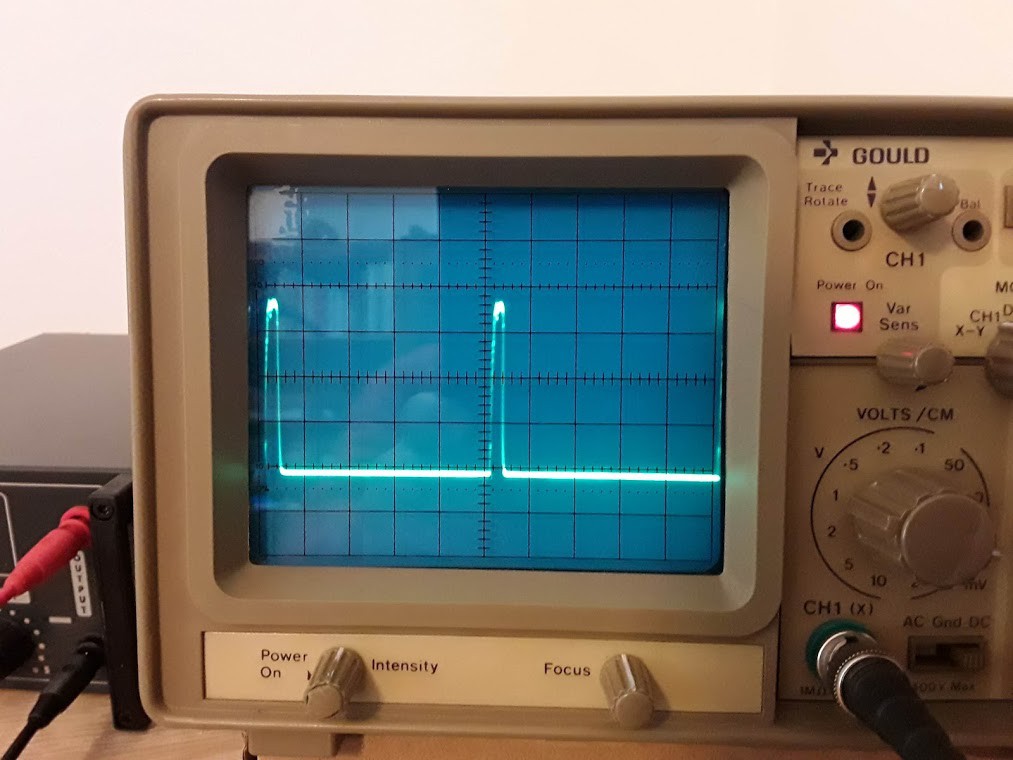
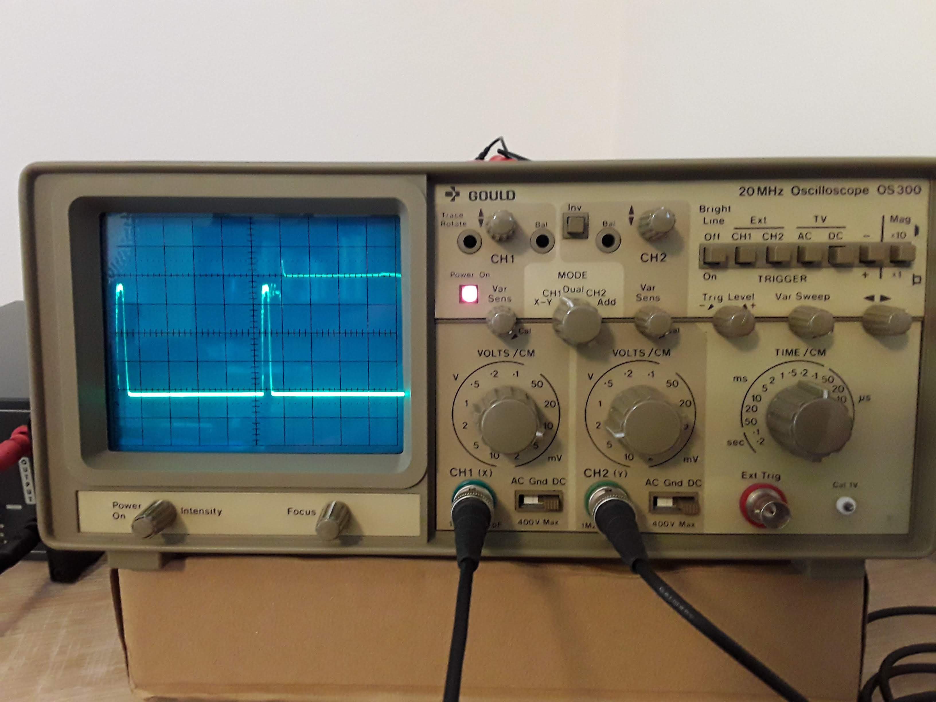
As expected I found a current peak at 1 KHz consistent with what I set in the software.
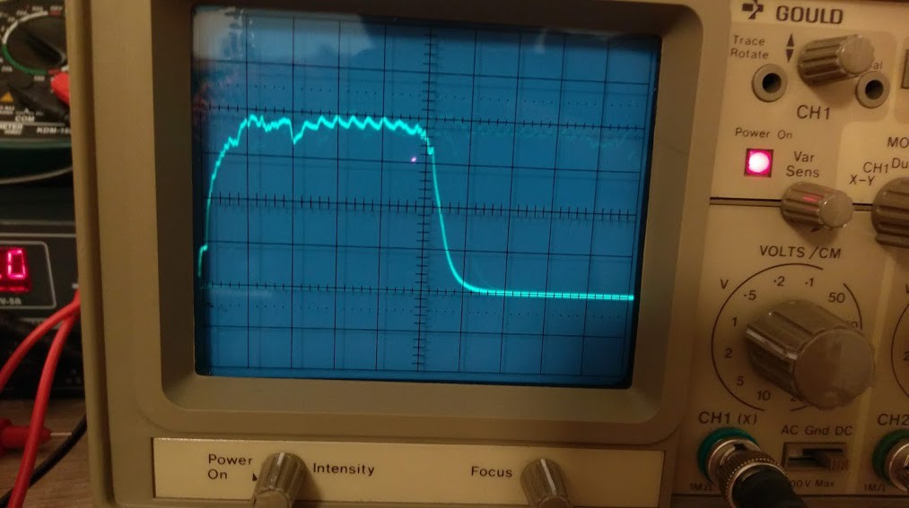
Fun fact: you can actually see when the MCU puts the 7 column pins high to check on the key presses.
So, what's the battery usage?
The current draw for a key kept pressed is:
where:
idle duration
idle current draw
current peak duration
current peak draw
Please note that the number of keys being pressed doesn't change the current draw.
We can suppose this is the behavior as long as you keep typing on the keyboard (Actually the firmware goes back to sleep when it detects no key being pressed for 500 ms, so you have to type at under 60 characters per minute to trigger the deep sleep, which is unlikely).
So, knowing the battery is rated for 220 mAh, we get:
HP: Let's say you work 8h a day. We can suppose you type continuously for half your work hours (a bit of a stretch but bear with me). So 4h per day means the battery lasts:
Not bad.
TLDR: Given the data I collected I can expect the battery to last at least a year. Obviously YMMV.
Here's the latest measurements of the batteries' voltage:
Left hand voltage
Right hand voltage
30/09/2018
2.98
3.04
06/10/2018
2.98
2.99
13/10/2018
2.96
2.97
20/10/2018
2.97
2.98
27/10/2018
2.97
2.98
10/11/2018
2.98
2.98
I don't quite know how to interpret this data points. The outside temperature lowered these last weeks thus influencing the voltage reading of the batteries. I should probably adjust the next readings to the temperature to actually know what's going on since I didn't take into account its role in the reading initially...
Battery usage quick update and Redox Wireless release.
Here's the latest measurements. The batteries seems to have stabilized around these values, I might need to find a multimeter with higher resolution to better check the voltage.
Left hand voltage
Right hand voltage
30/09/2018
2.98
3.04
06/10/2018
2.98
2.99
13/10/2018
2.96
2.97
20/10/2018
2.97
2.98
I now feel sufficiently confident with the power consumption to release the PCB files as open source on the Redox project repository. Here you'll find:
The transmitters gerber files
The receiver gerber files
The KiCad project files
The KiCad footprint library files I've used
I'm also merging the Redox firmware sources into the QMK firmware project. I'll still monitor the battery usage in the following weeks and report regularly.
In the last two week I used my wireless Redox as my daily driver at work. This means that I use the keyboard 8 hours a day, 40 hours a week and shut it off before going home. It stays powered off during the weekend. I would say that my usage is medium-high since I have a keyboard-centric workflow (I use i3, vim and clion with vim plugin on my workstation), so take this into account.
I measured the battery voltage every weekend and these are the results:
Left hand voltage
Right hand voltage
30/09/2018
2.98
3.04
06/10/2018
2.98
2.99
13/10/2018
2.96
2.97
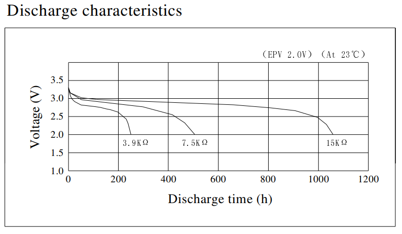
I know I have not enough data but I will try to make a guesstimate anyway. I would approximate the voltage drop to 0.02 V per week of usage. Looking at the CR2032 datasheet
we can assume a linear discharge down to 2.5 V.
With these data I estimate that a battery could last 25 weeks or 6 months (0.02 V drop per week starting from 3.0 V), in other words 1000 h of battery life. This is without considering that the MCUs are rated for a minimum 2.0 V operating voltage.
This seems pretty good actually.
Anyway I wouldn't take this estimate as definitive since I have not enough data yet. In the next two weeks I'll keep the battery monitored and report the usage.
As you might guess from the video above I finally received the case from Falbatech. It needed some little adjustments but now it's perfect.
Here's some pics.
Everything's ready.
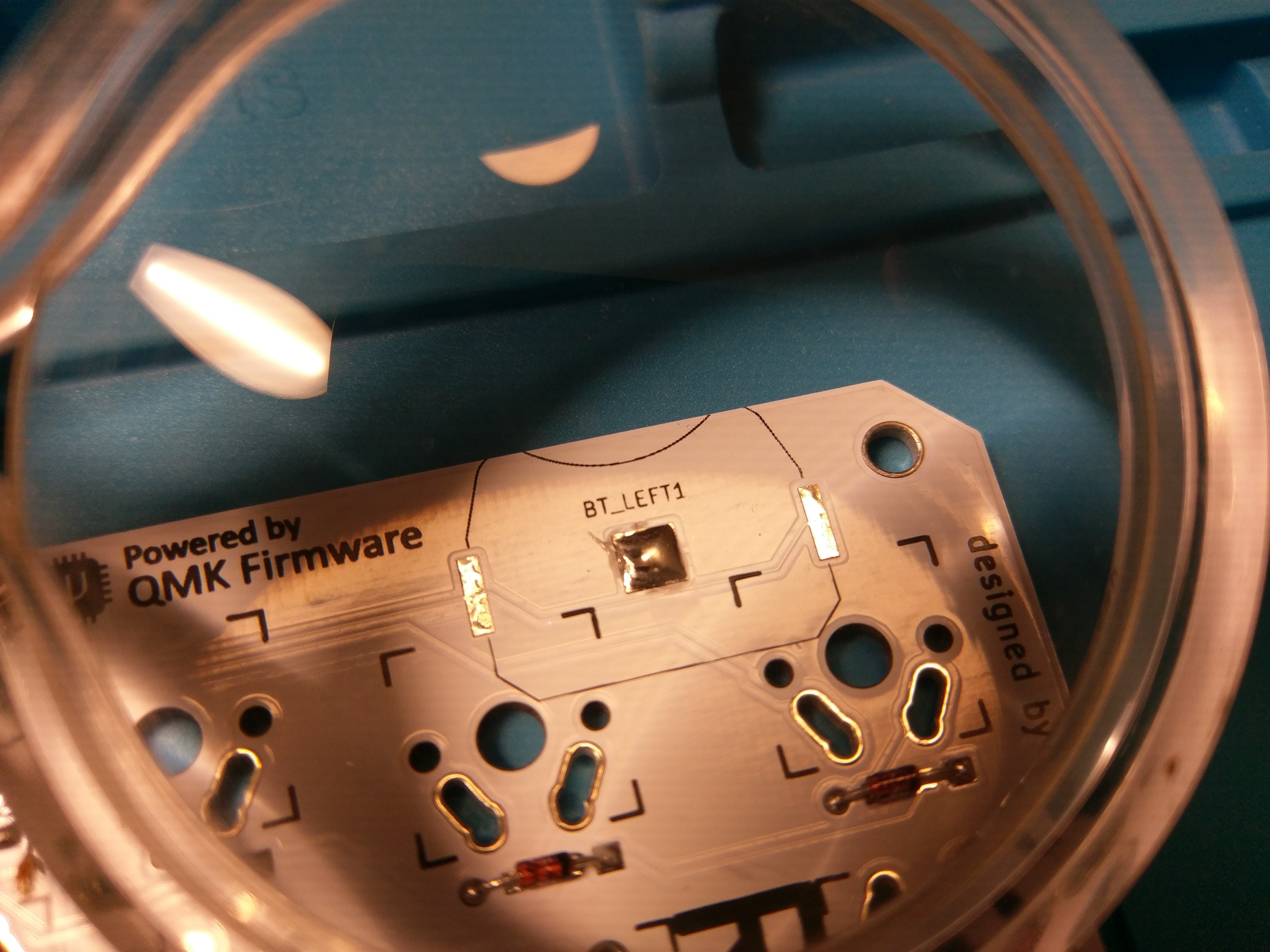
Perfect fit.Well... almost perfect fit. This case is designed for the standard Redox, so I had to adapt it to my needs. As you might notice the battery is lower than the case border, it fits but it was difficult to remove it from the holder. All it needed was some filing.I traced some mark to know where to file.Perfect.Time to solder the switches.For this build I used some Cherry MX silent red switches. Since I plan to use it at my job I need to be as silent as possible. Here I put a few switches and soldered them to keep the PCB in place as I added all the remaining switches.Rince and repeat.
I also assembled the Mitosis receiver separately. My breadboard-based receiver isn't as nice as this one.
Sexy!
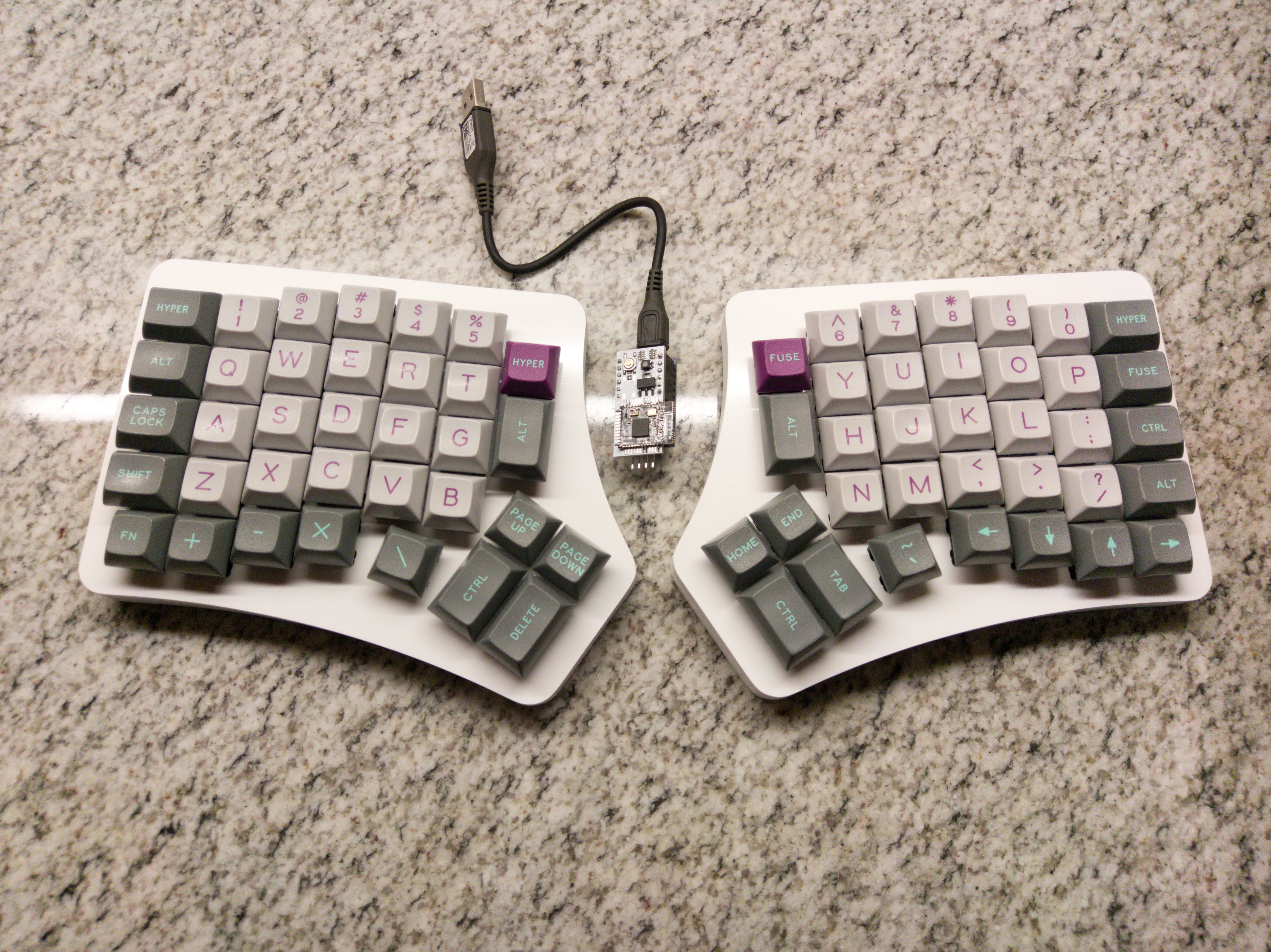
Here we are. The finished product.
I'm writing this log with it and i find it really comfortable to use without having a mess of cables around. I think that a split keyboard really shines when there's no cables to limit its positioning. I love it!
So... what now? I will put the assembly instruction on the Redox repository in the next few days and I will report on the battery usage whenever I can.
I hope you enjoyed this build as much as I did. It took me longer than I initially tought but I think the final product was well worth the effort.
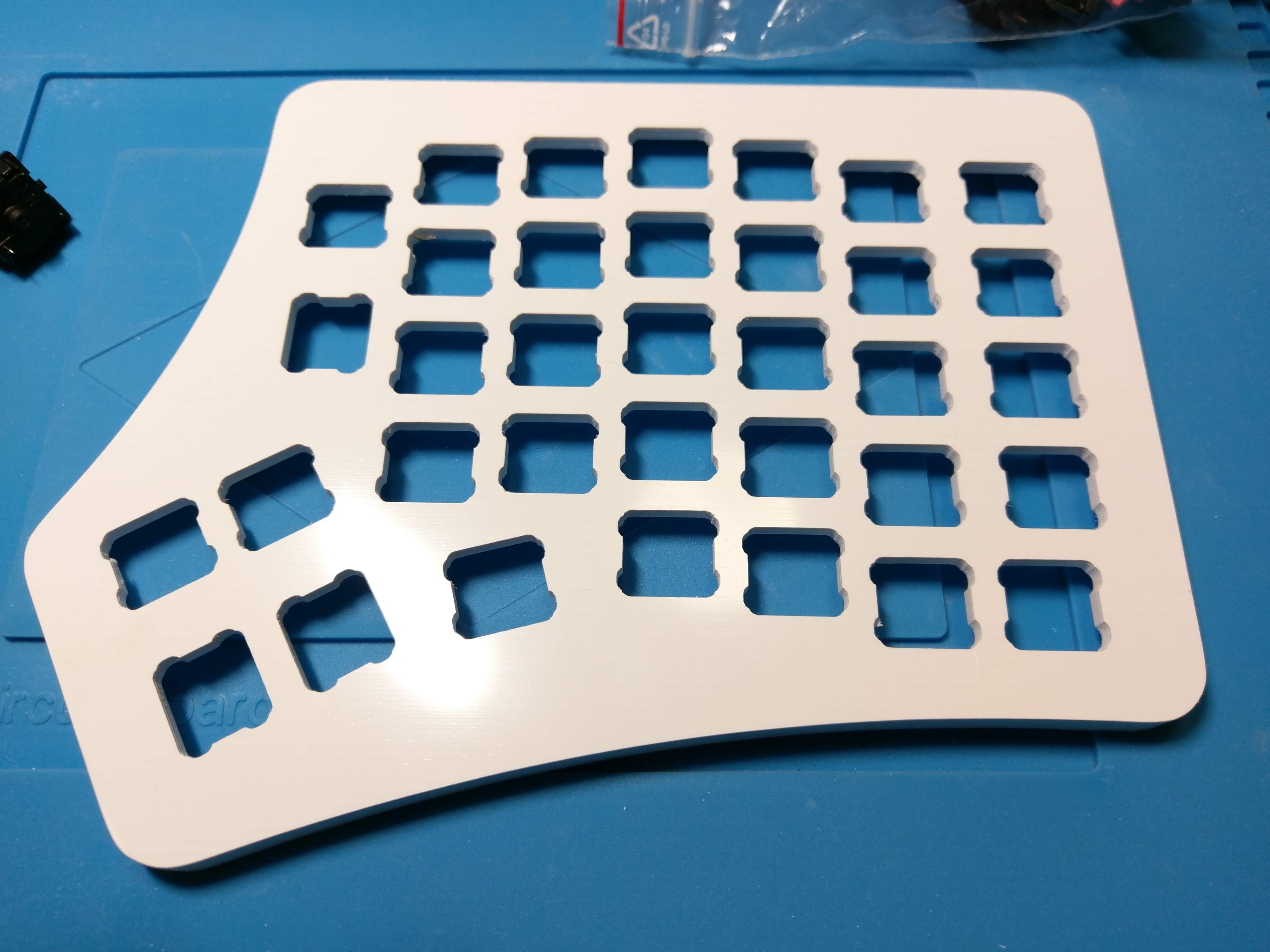
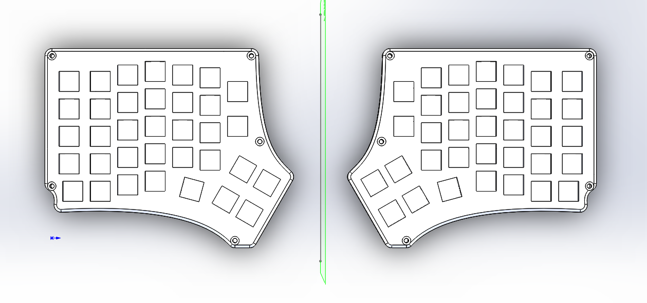
Since one of my goal is to make this keyboard affordable, I designed a 3D printable case in the past for the first revision. Now I'll do the same starting from the same case.
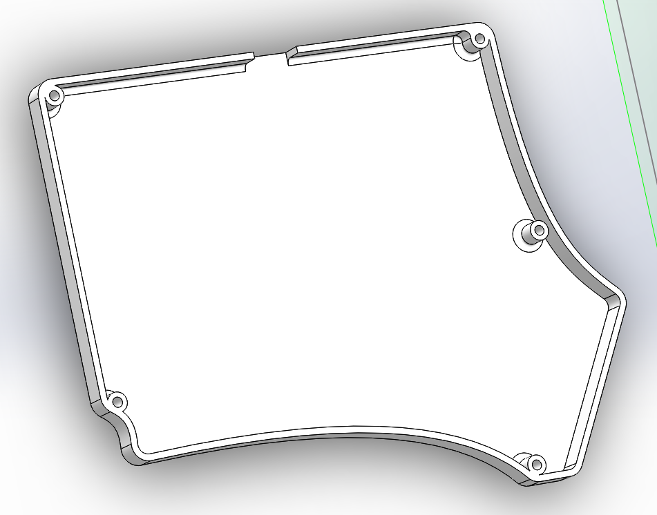
Here's some pics of the design:
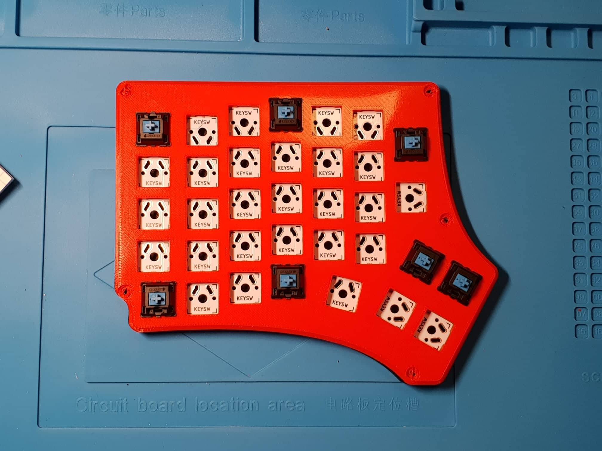
Note: the PLA filament is pretty flexible and it's not the best material for a keyboard plate but I tried my best to make it nice to use. I designed the plate to be 4mm thick with a cutout for the plastic stabs in the switches to grip on. I followed the mechanical drawing here:
The main difference in the case design from the past revision is the bottom half. For the Wireless version we don't need to be as high as before since we don't need to make space for USB connectors and such.
Here's the timelapse of the print thanks to my cousin Filippo, owner of the printer =D (Hephestos i3 MK2)
Perfect fit!This plate is great, 4mm is the perfect thickness for it. It doesn't flex and you I didn't take into account the stiffness of the PCB... this went much better than expected!
Components finally! (Well... at least some of them)
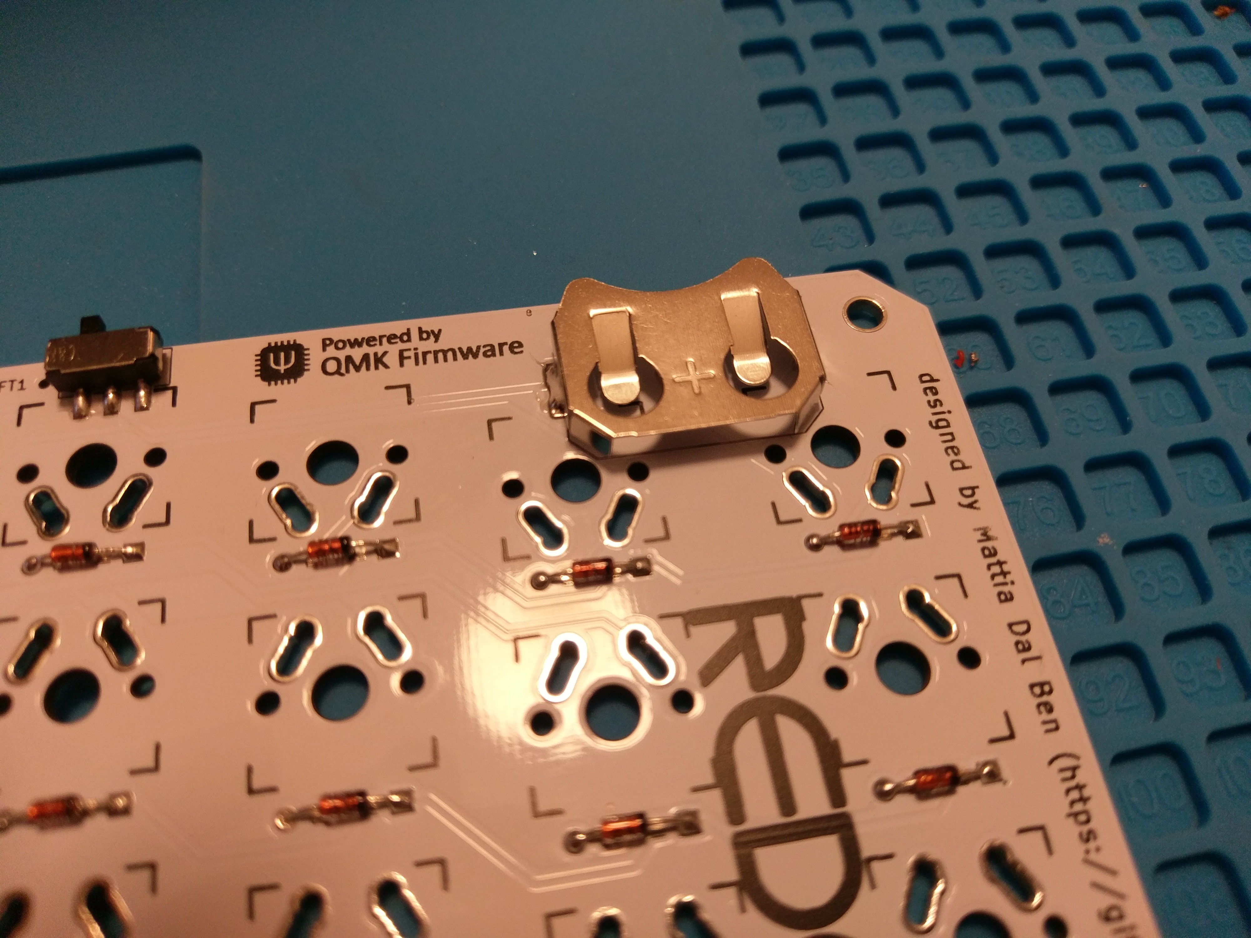
Yesterday I received the MCUs and some other parts for the keyboard. I'm still missing the CR2032 holders and the case. I hope they'll arrive soon...
Anyways here's some pics:
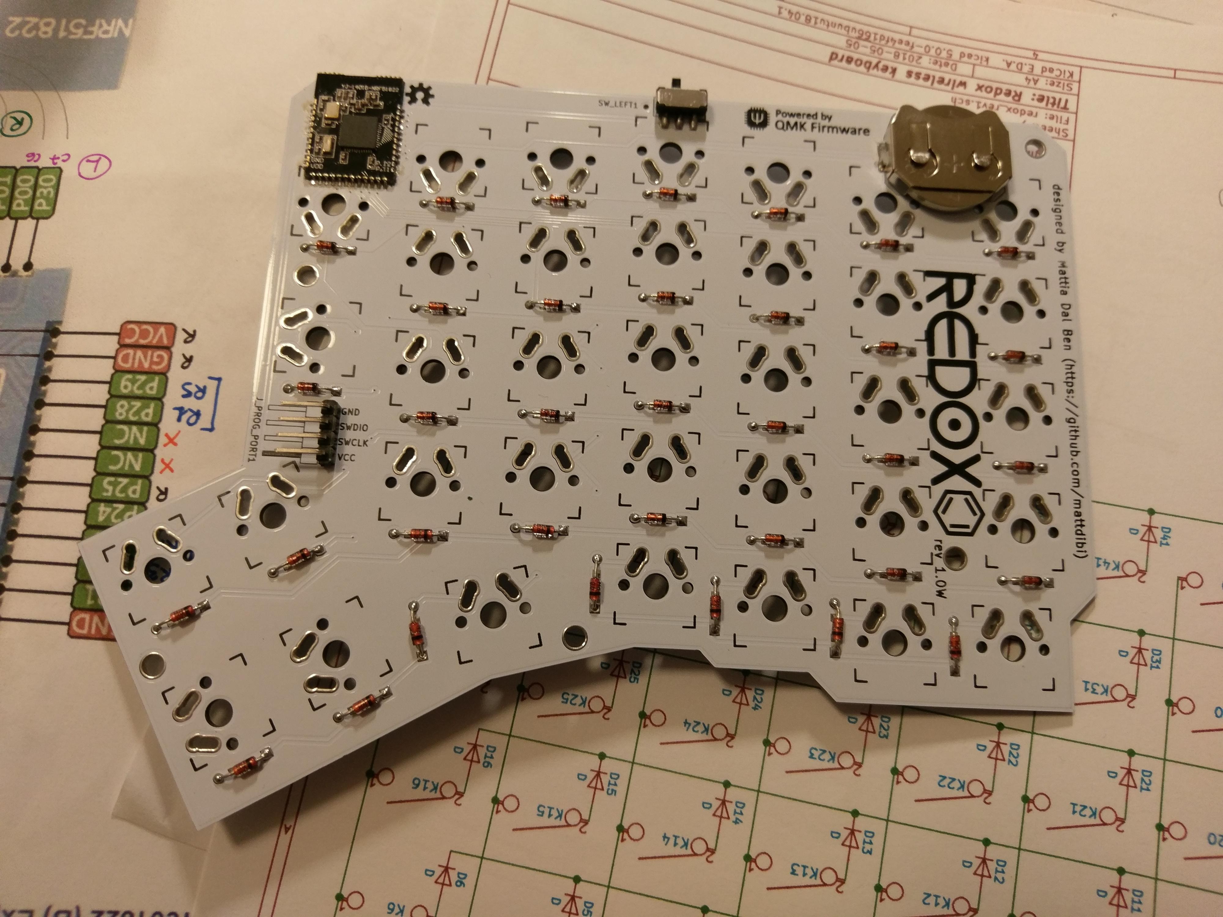
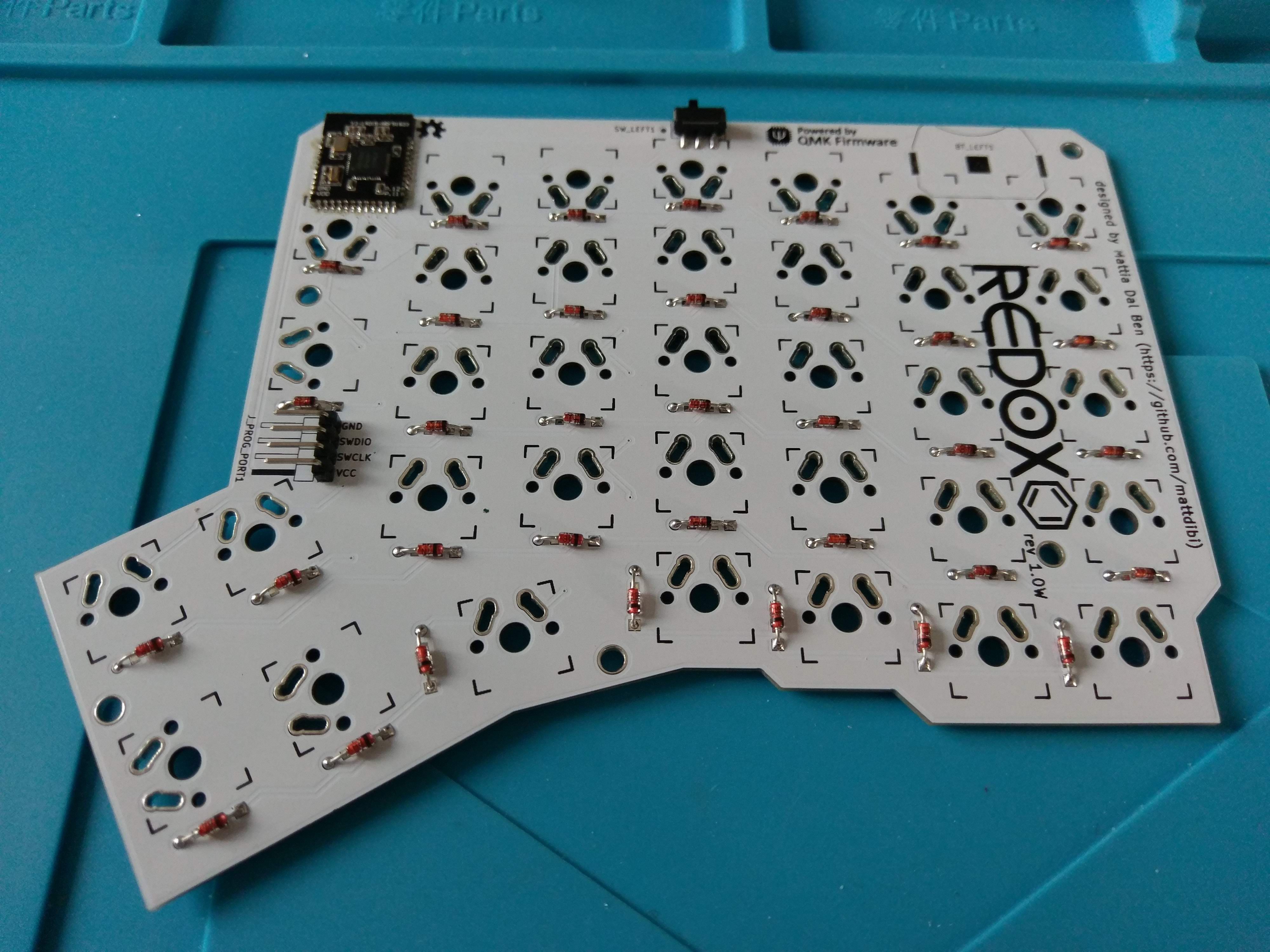
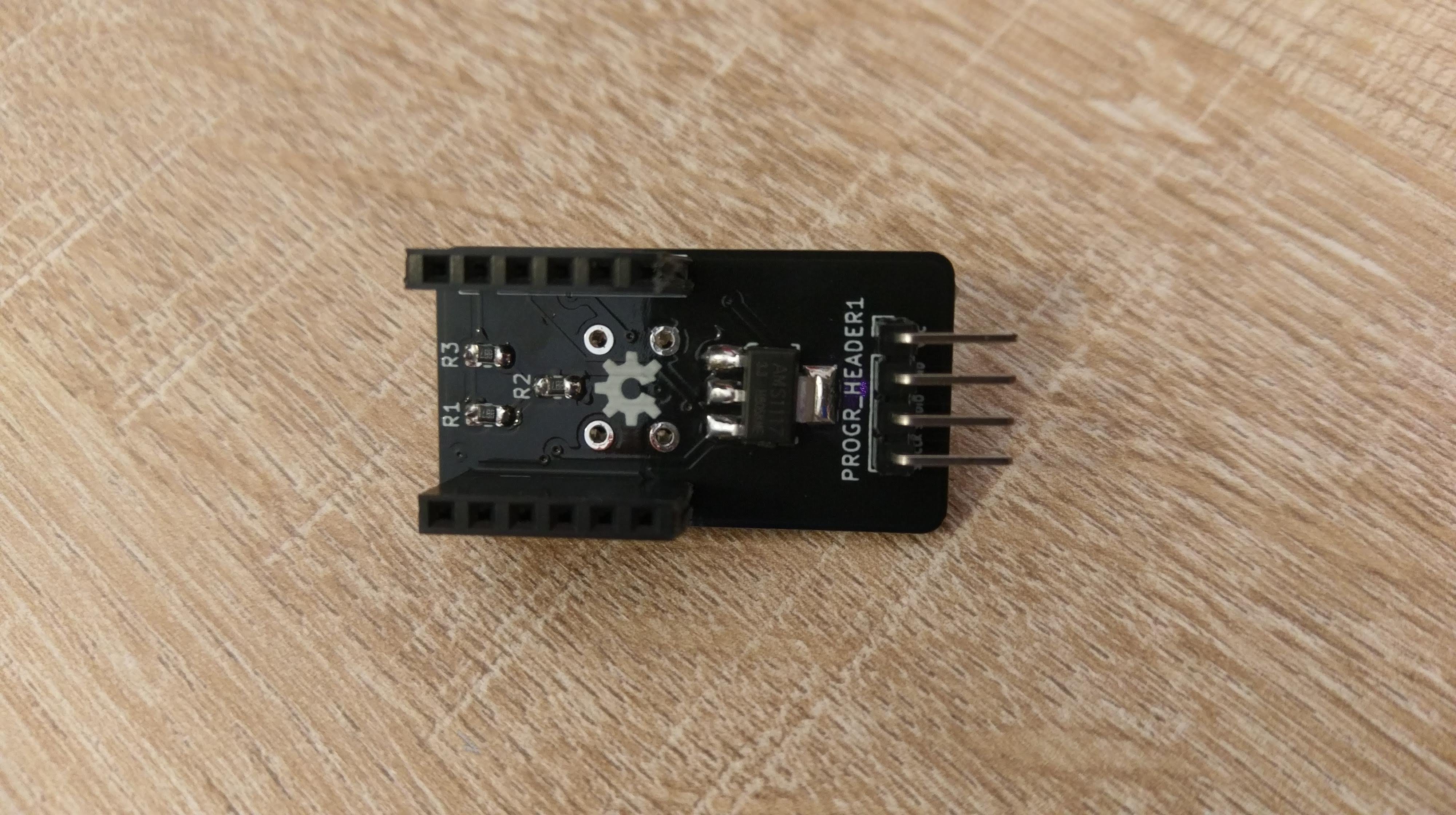
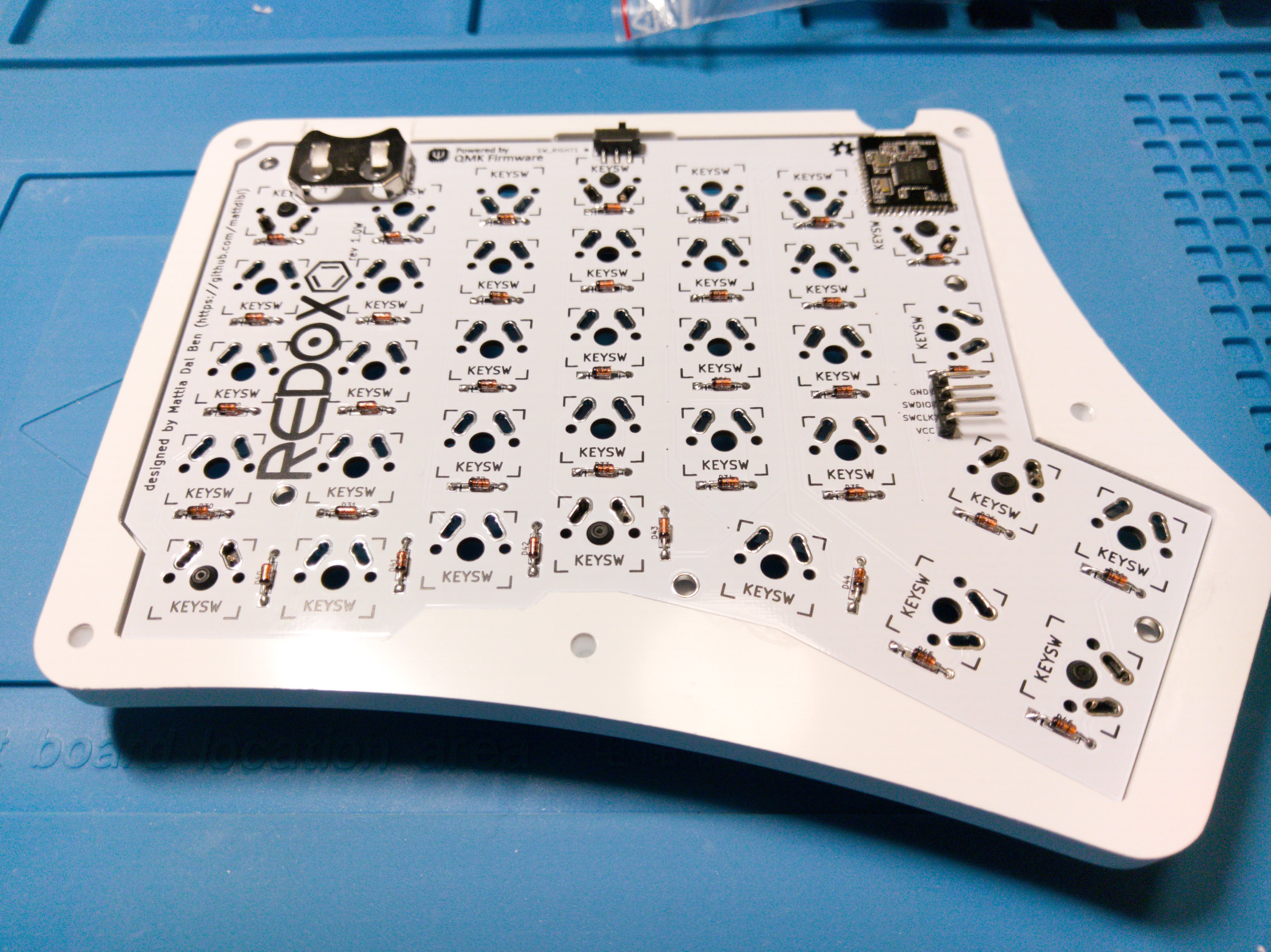
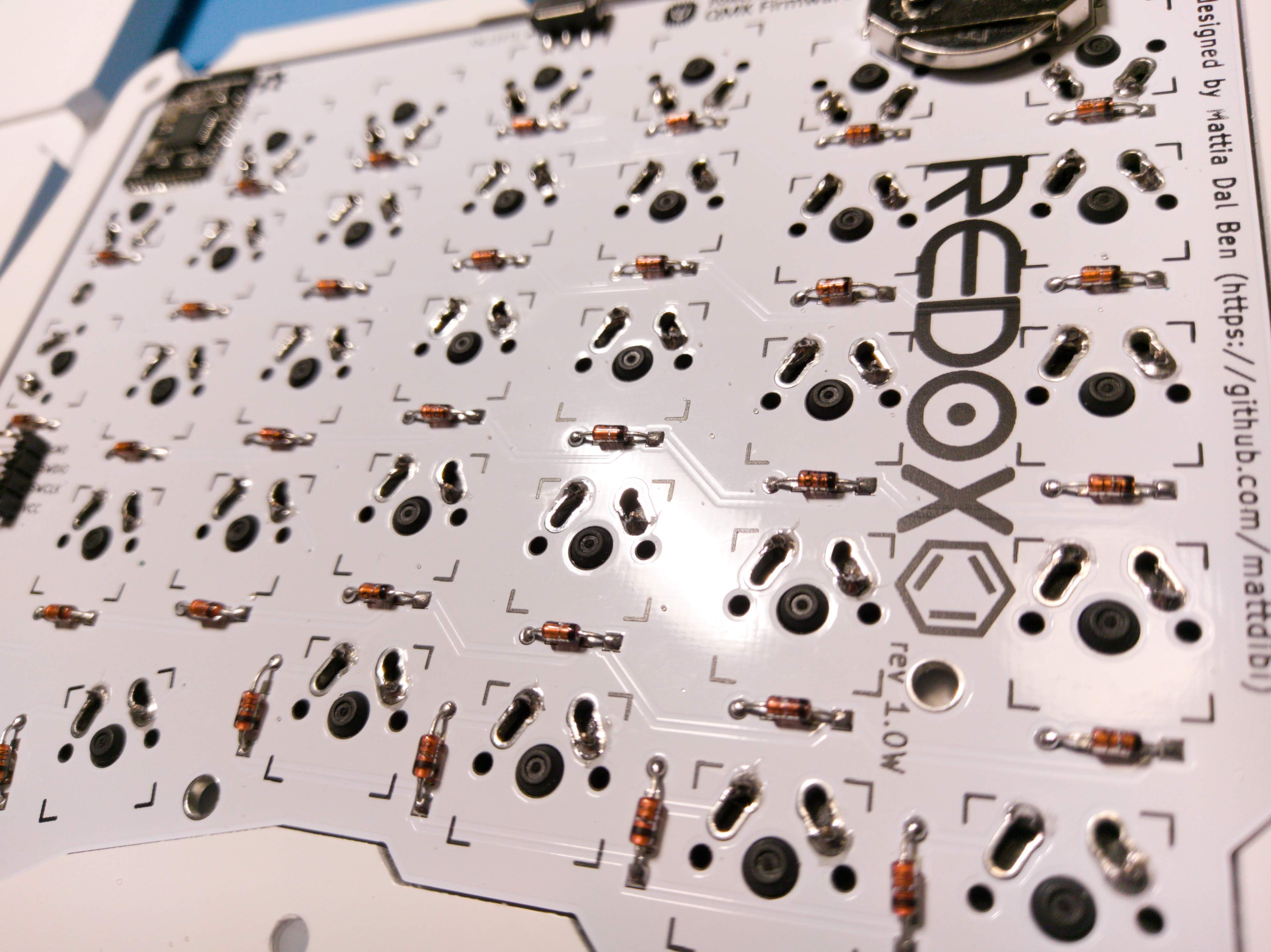
1N4148 diodes installed.
Angled programming header for the MCU.
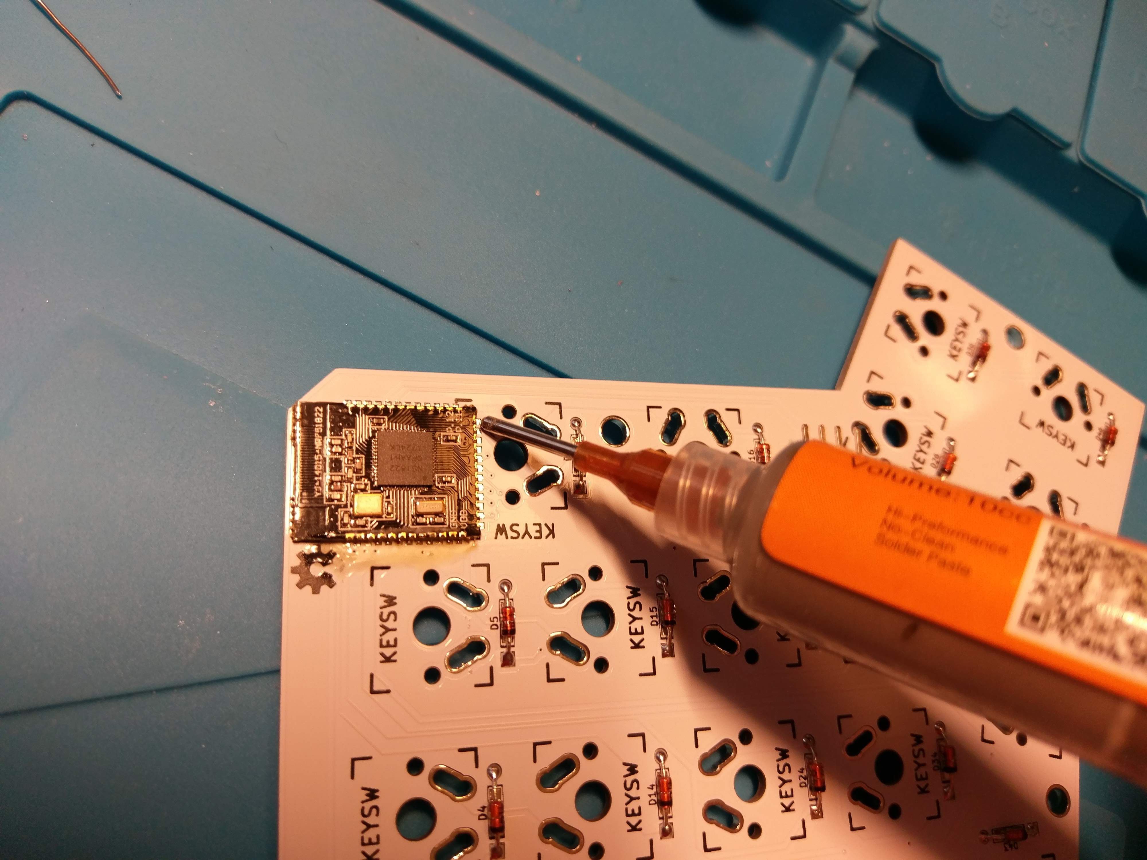
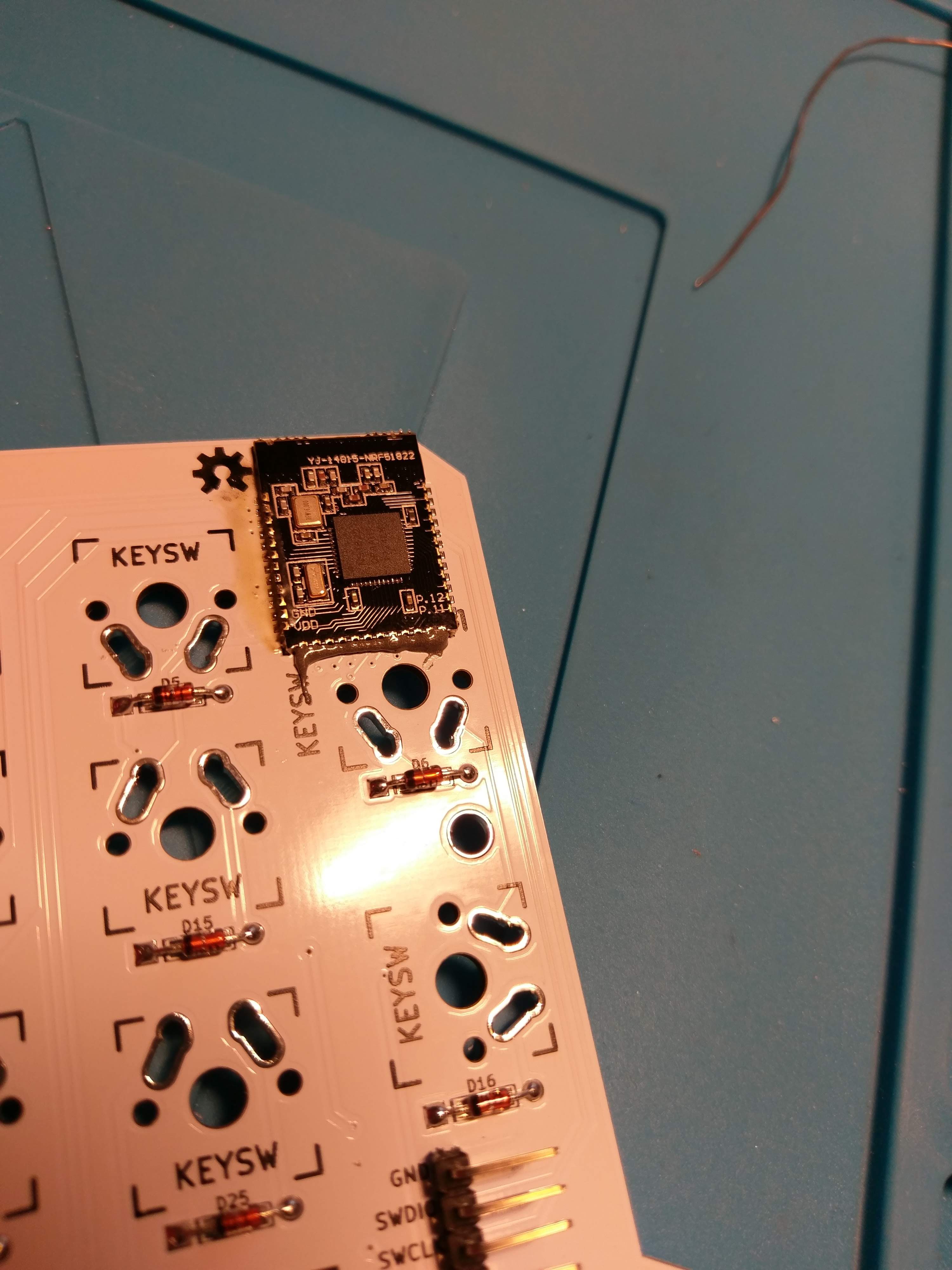
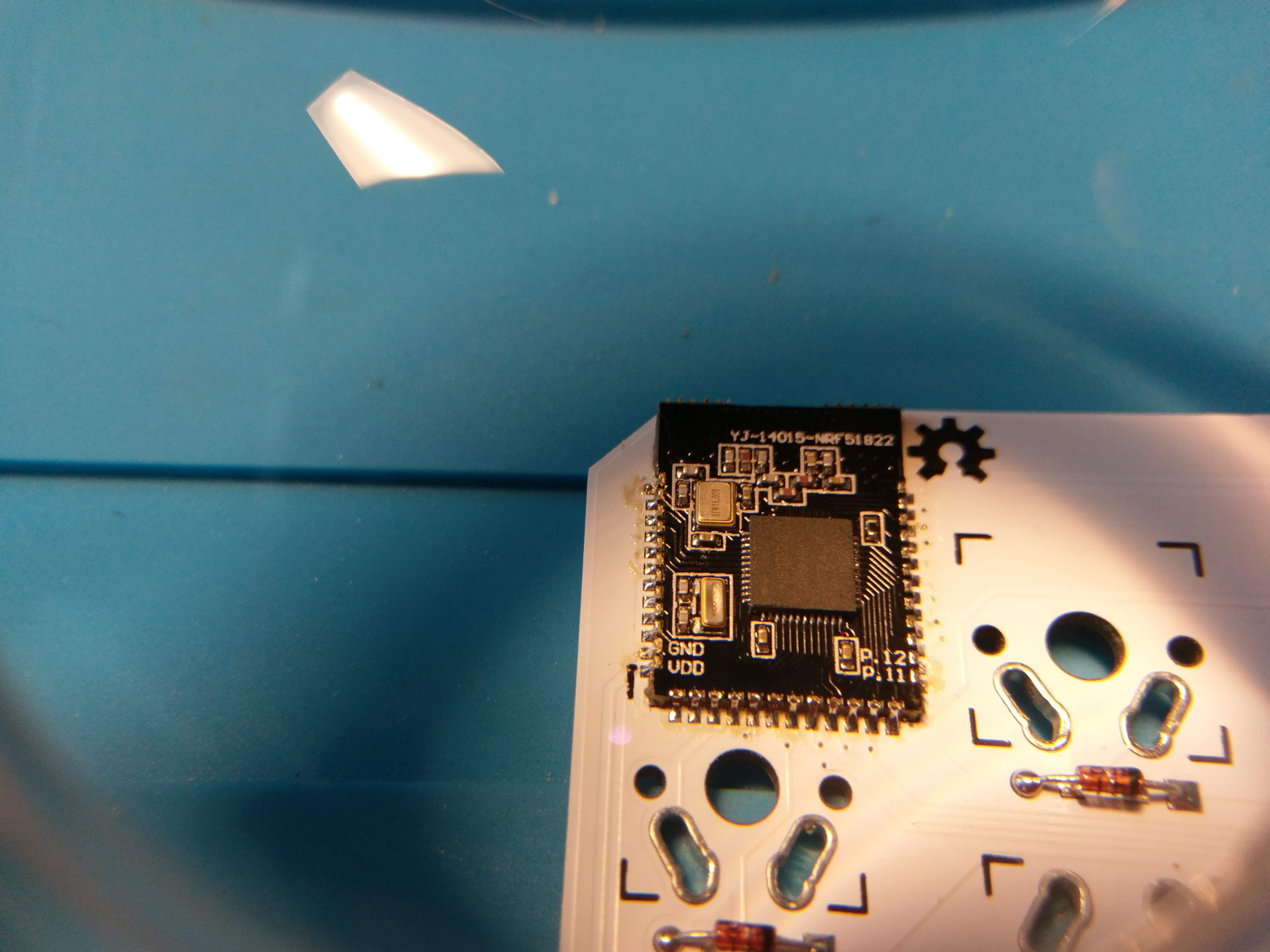
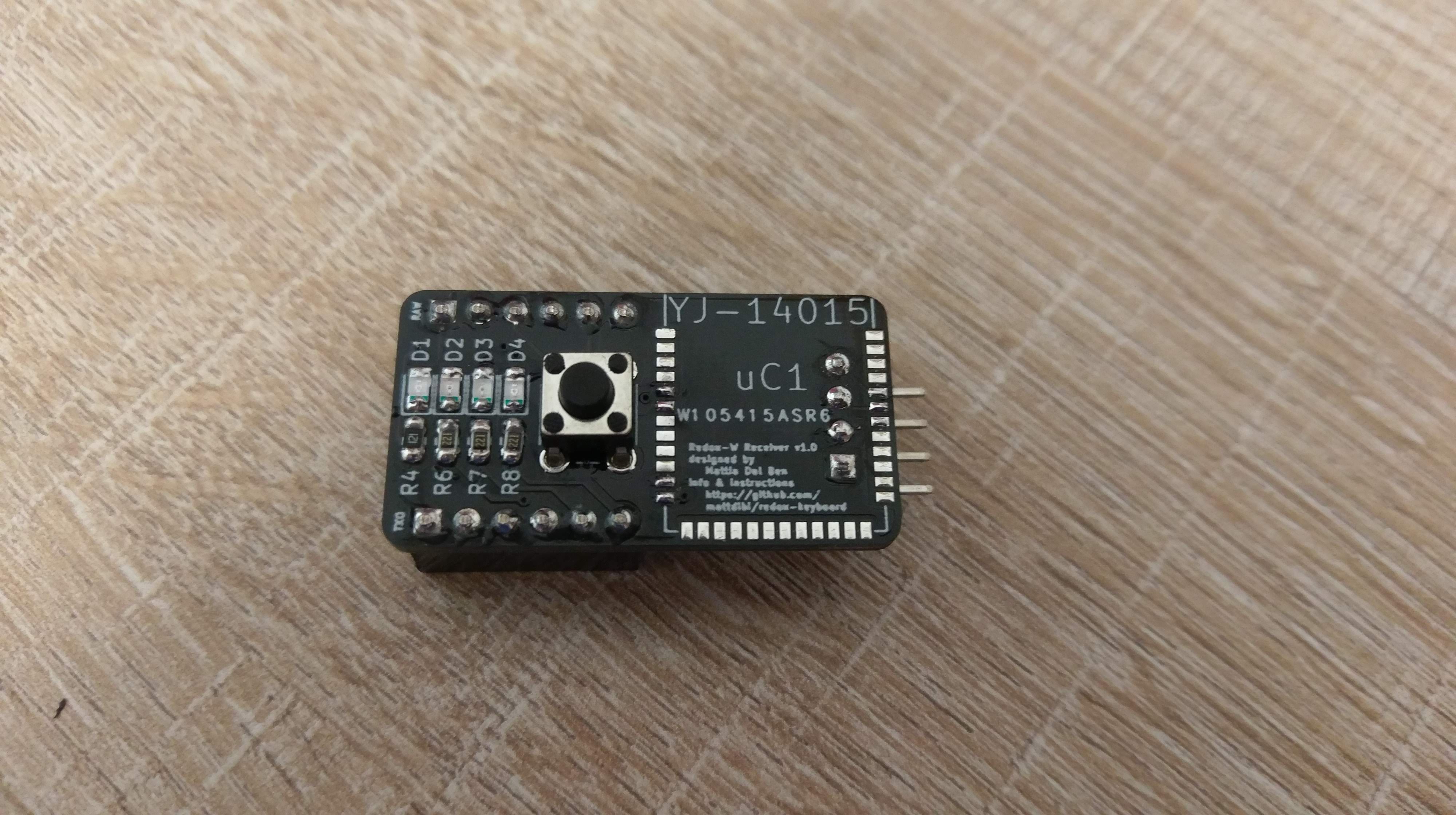
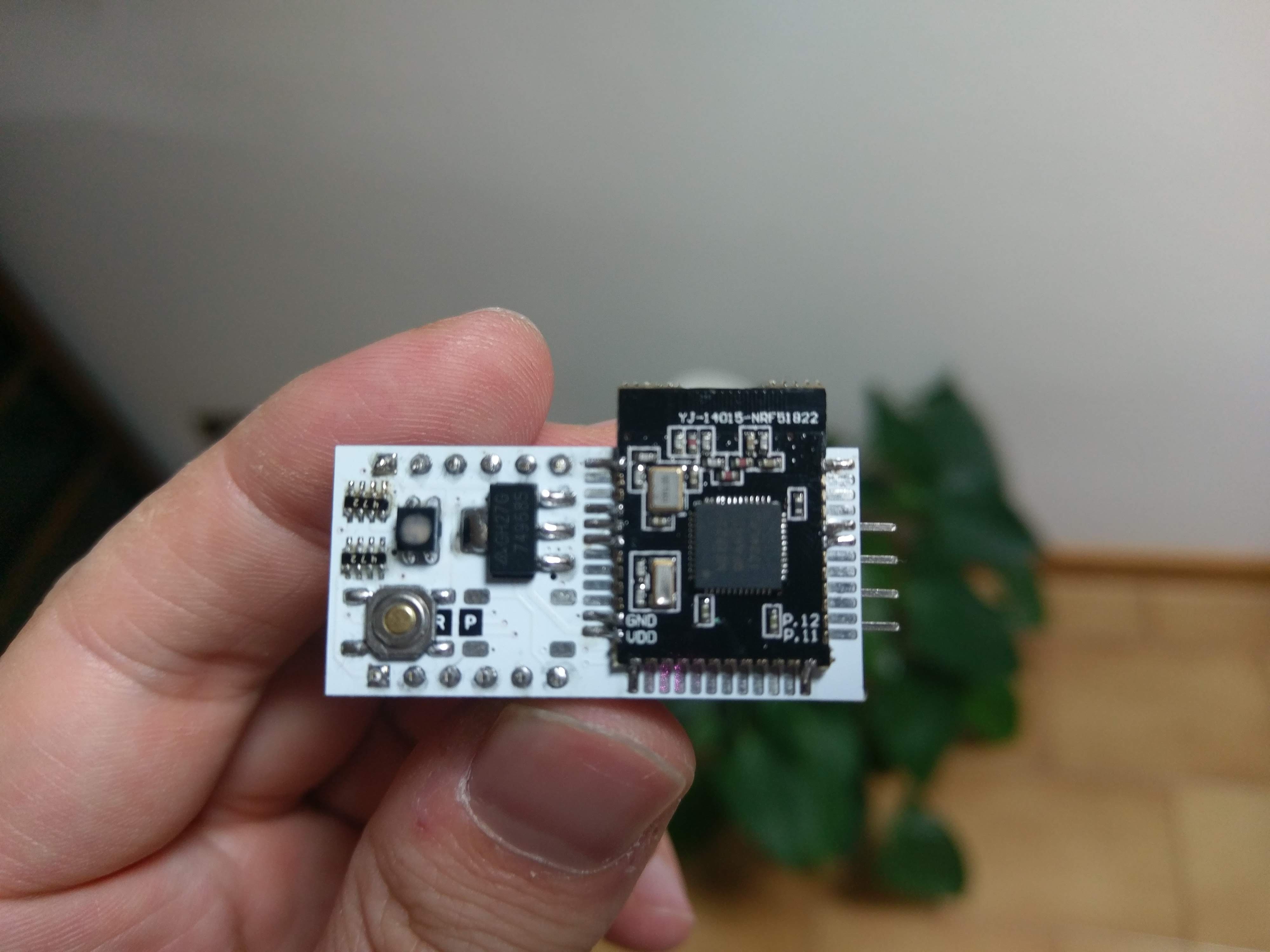
And now for the tricky part: the YJ-14015. I choose these because they are cheap and have a smaller footprint than the Core51822B but looking at them I was worried I couldn't solder them. Solder paste to the rescue!
This is the most difficult component I have ever tried to solder but with the solder paste it was a breeze. I put some masking tape on the MCU to keep it in place, then I added the paste. A quick pass with the soldering iron and the job was done. I did a few touch-ups with the tip of the iron here and there just to be sure.
Not bad.
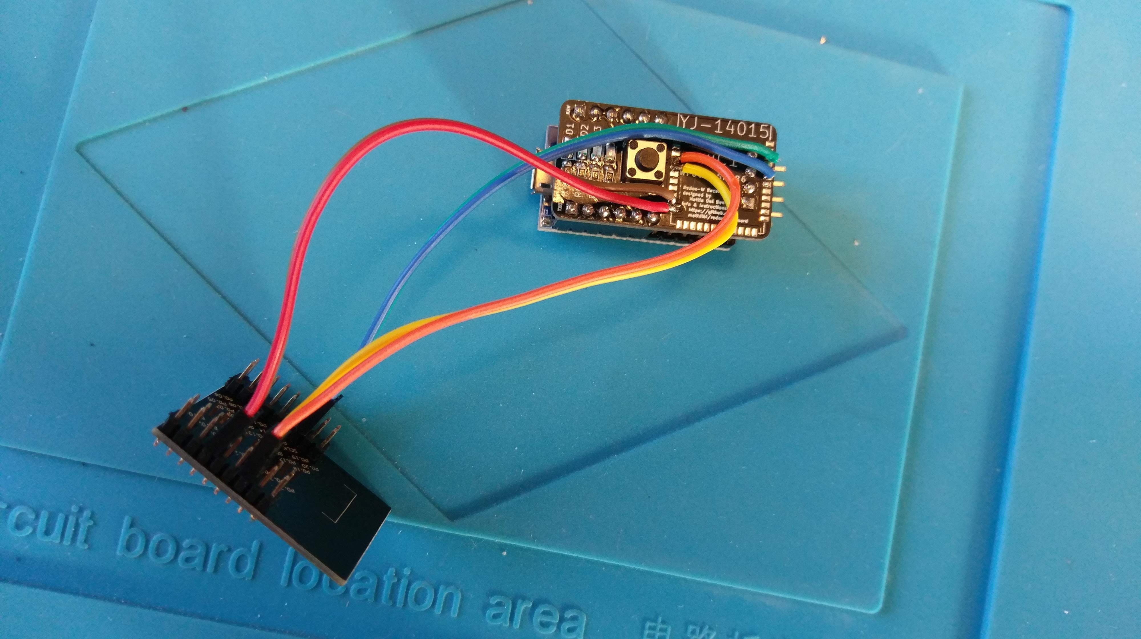
It's testing time!
Since I don't have the battery holders yet I improvised using the ST-Link programmer as a power source. After uploading the firmware...
I checked and all keys are registering. Excellent!
Now I need to wait for the last pieces of the puzzle and the keyboard is finished. Soon I'll update the Redox project repository with all the instructions and components needed for the project.
 Mattia Dal Ben

 Perfect fit.
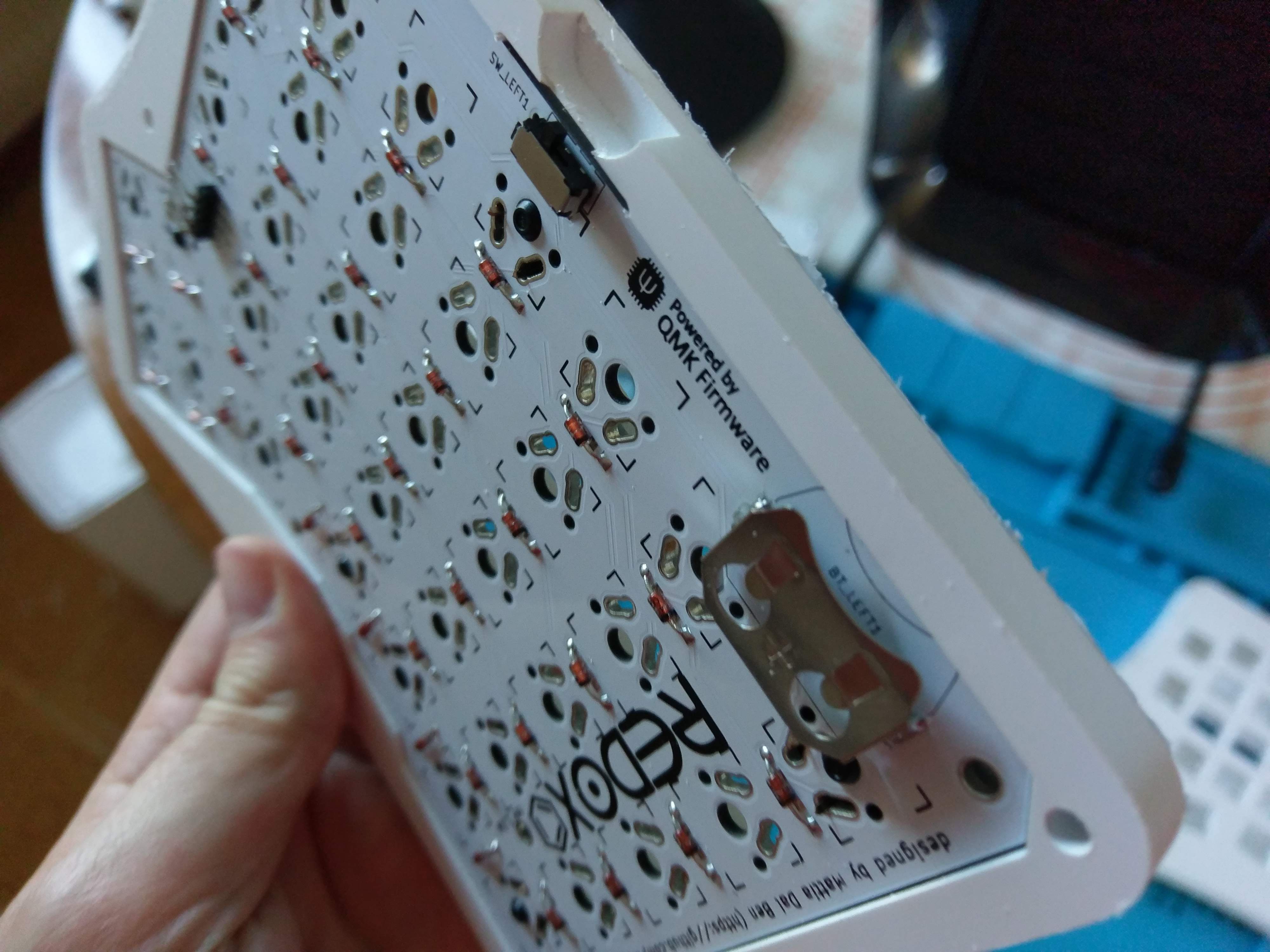 Well... almost perfect fit. This case is designed for the standard Redox, so I had to adapt it to my needs. As you might notice the battery is lower than the case border, it fits but it was difficult to remove it from the holder. All it needed was some filing.
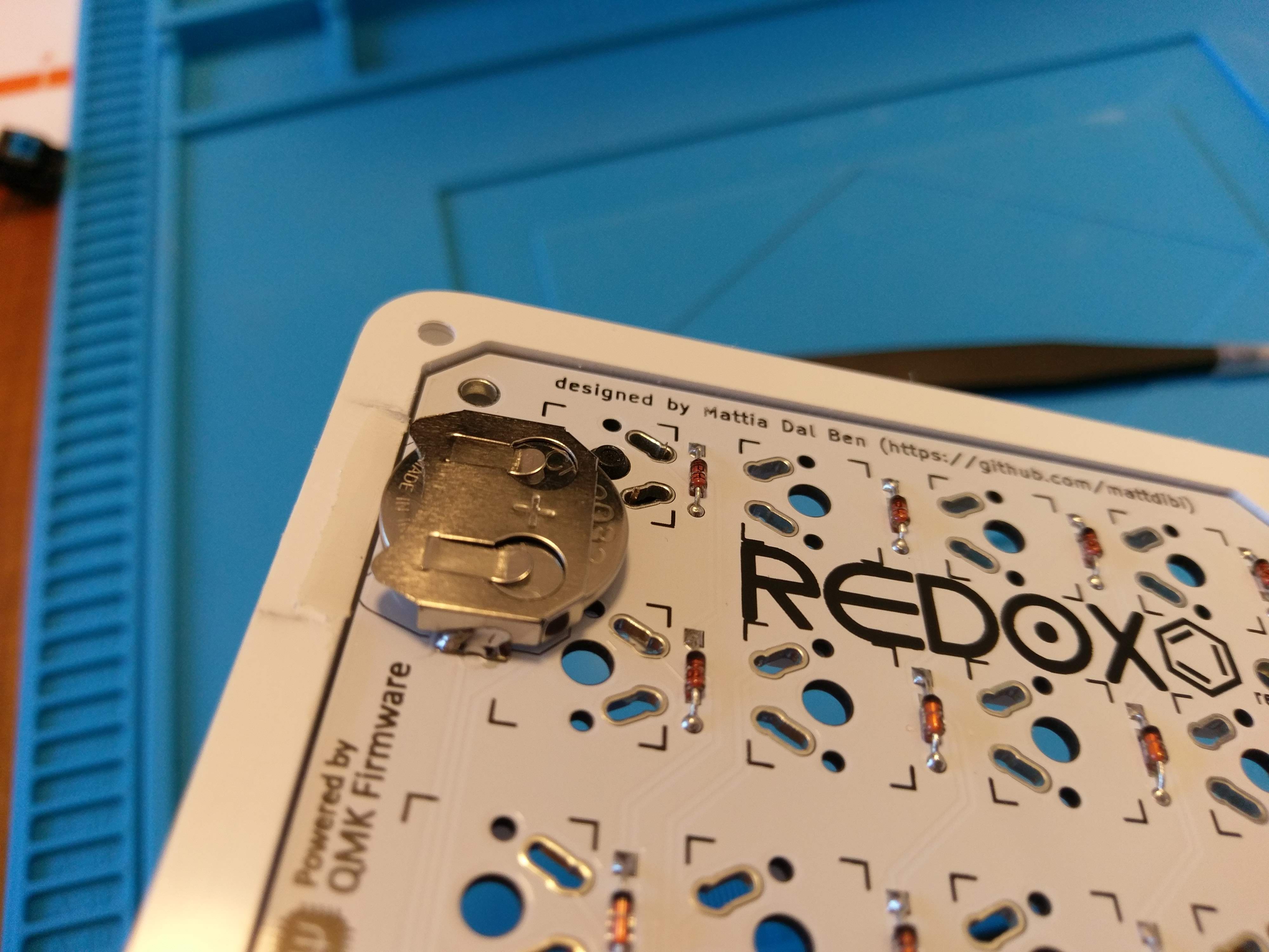
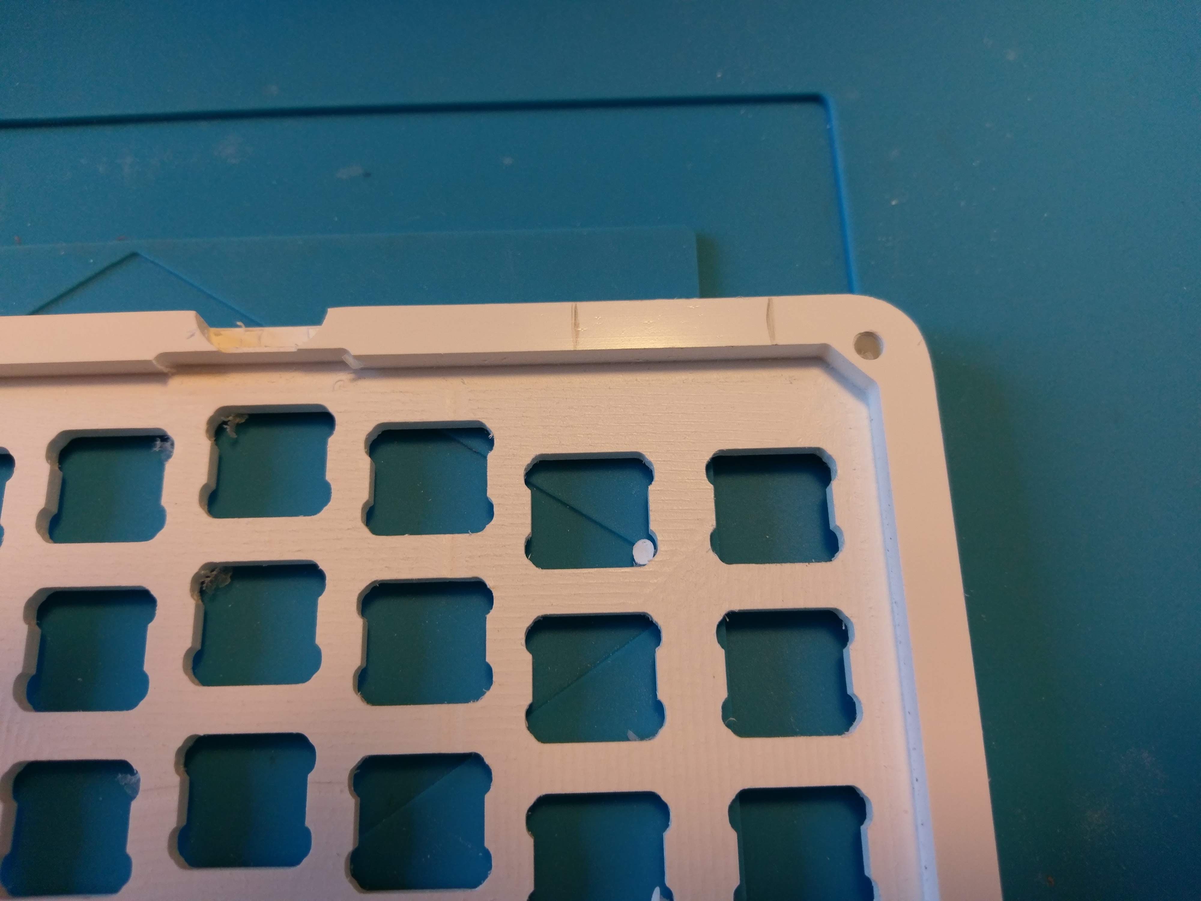 I traced some mark to know where to file.
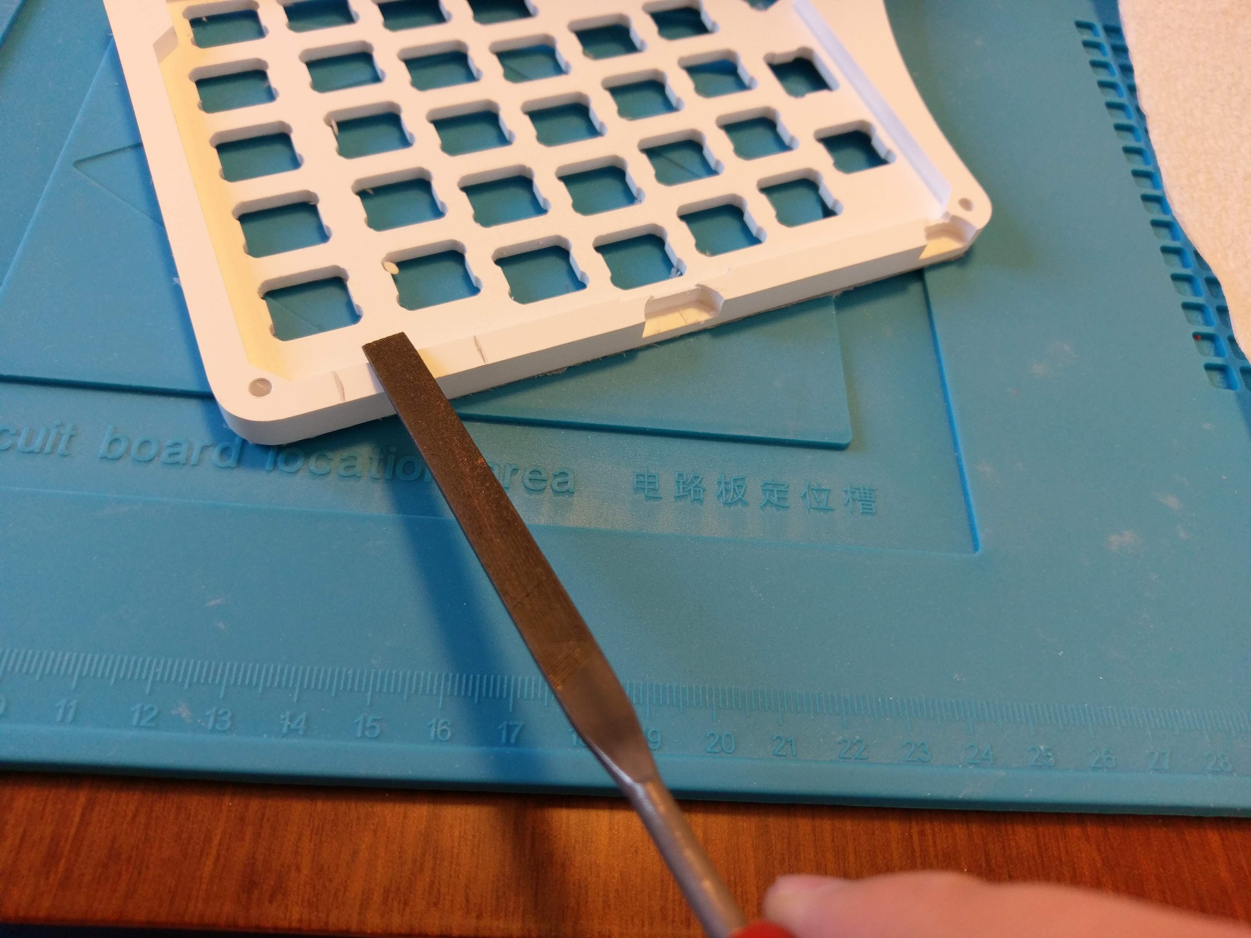
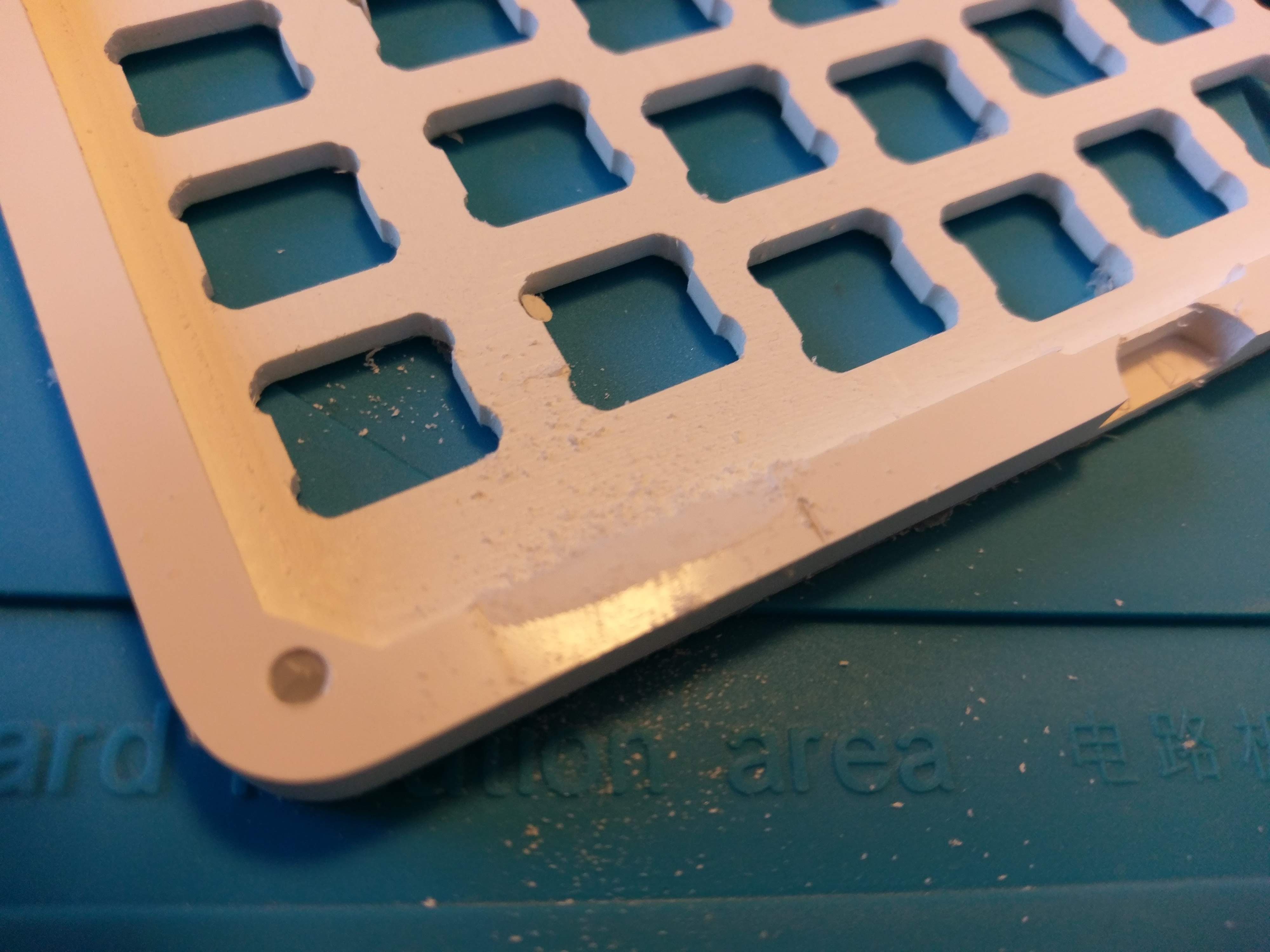
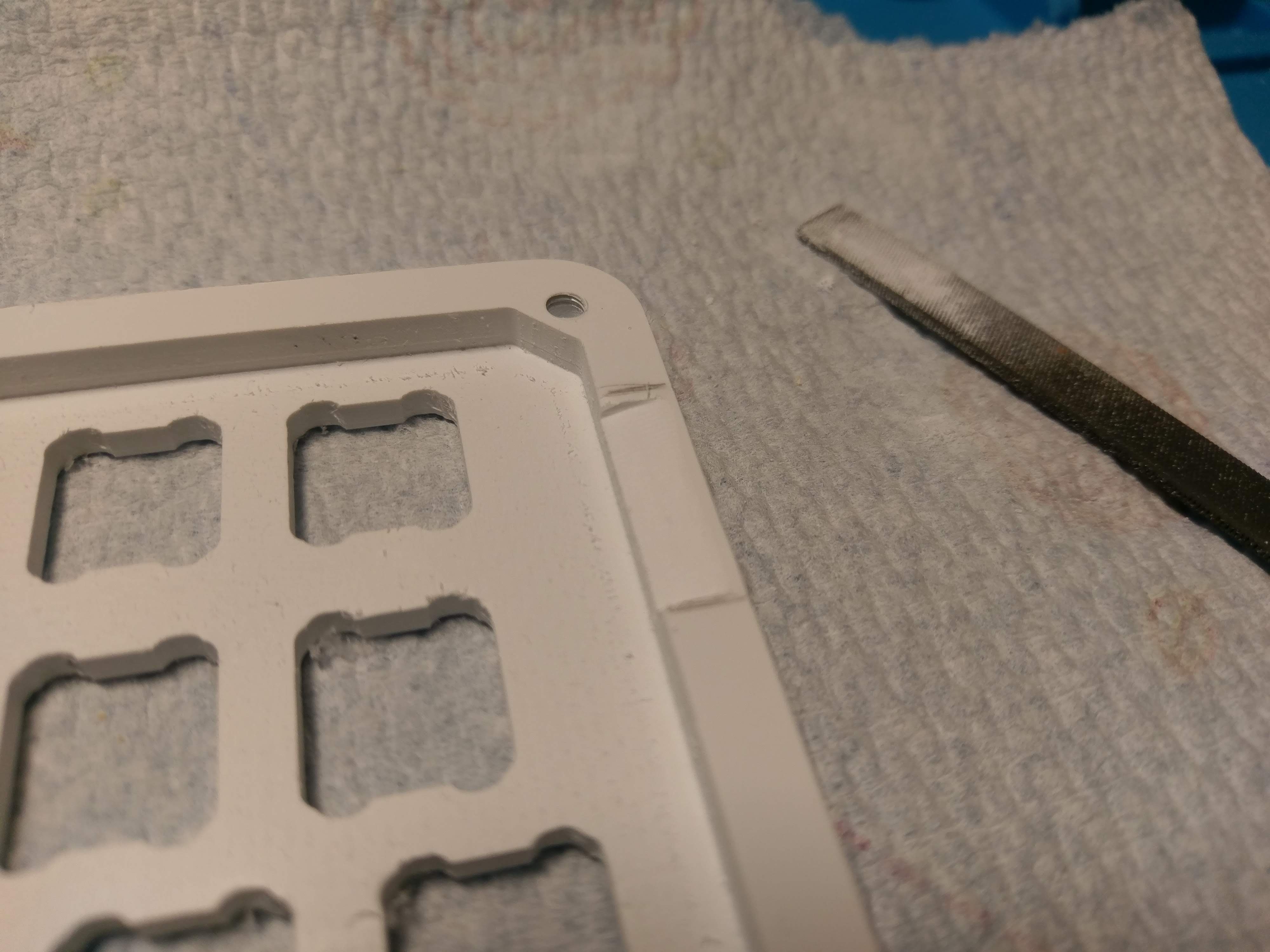 Perfect.
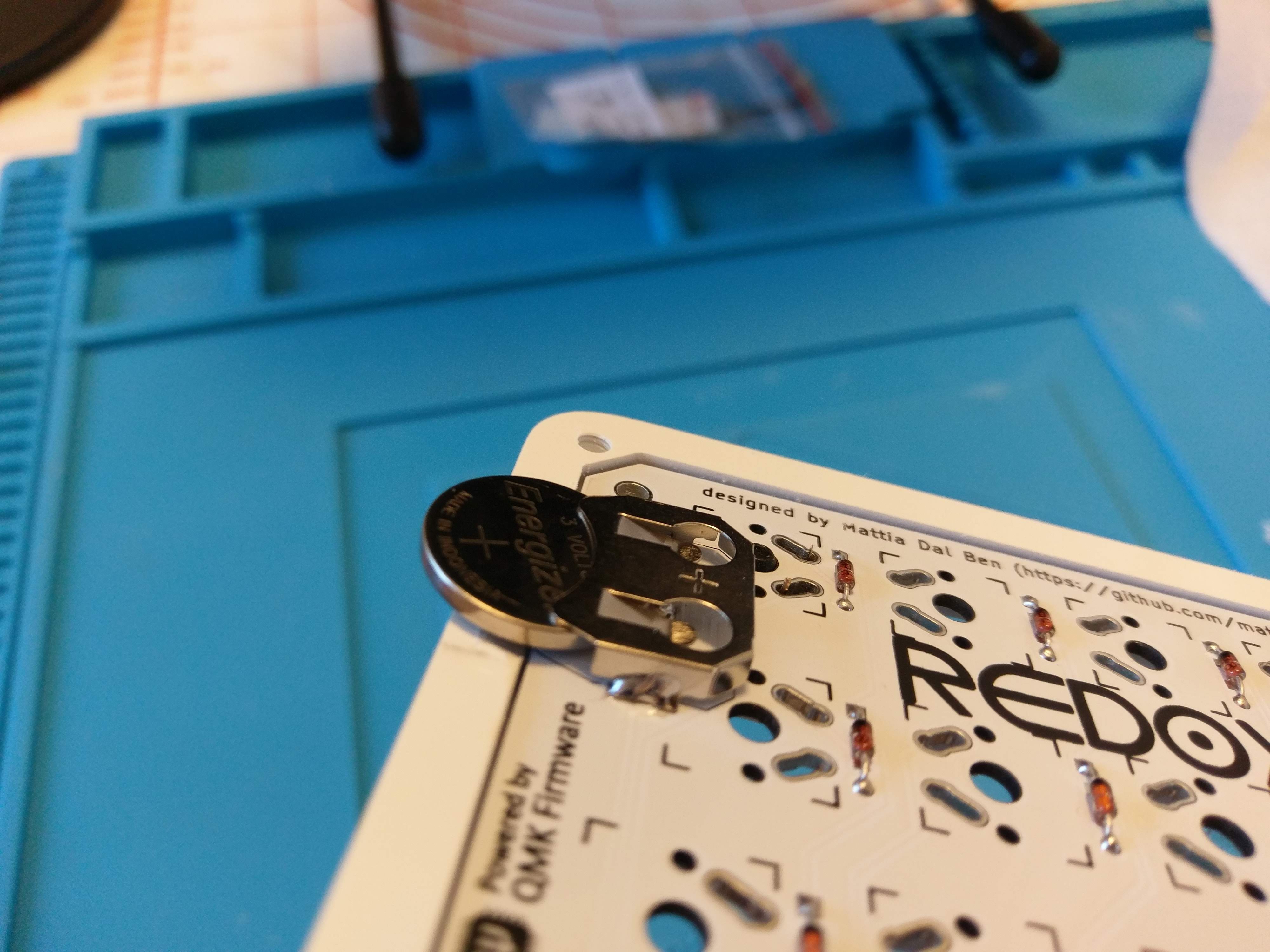
 Time to solder the switches.
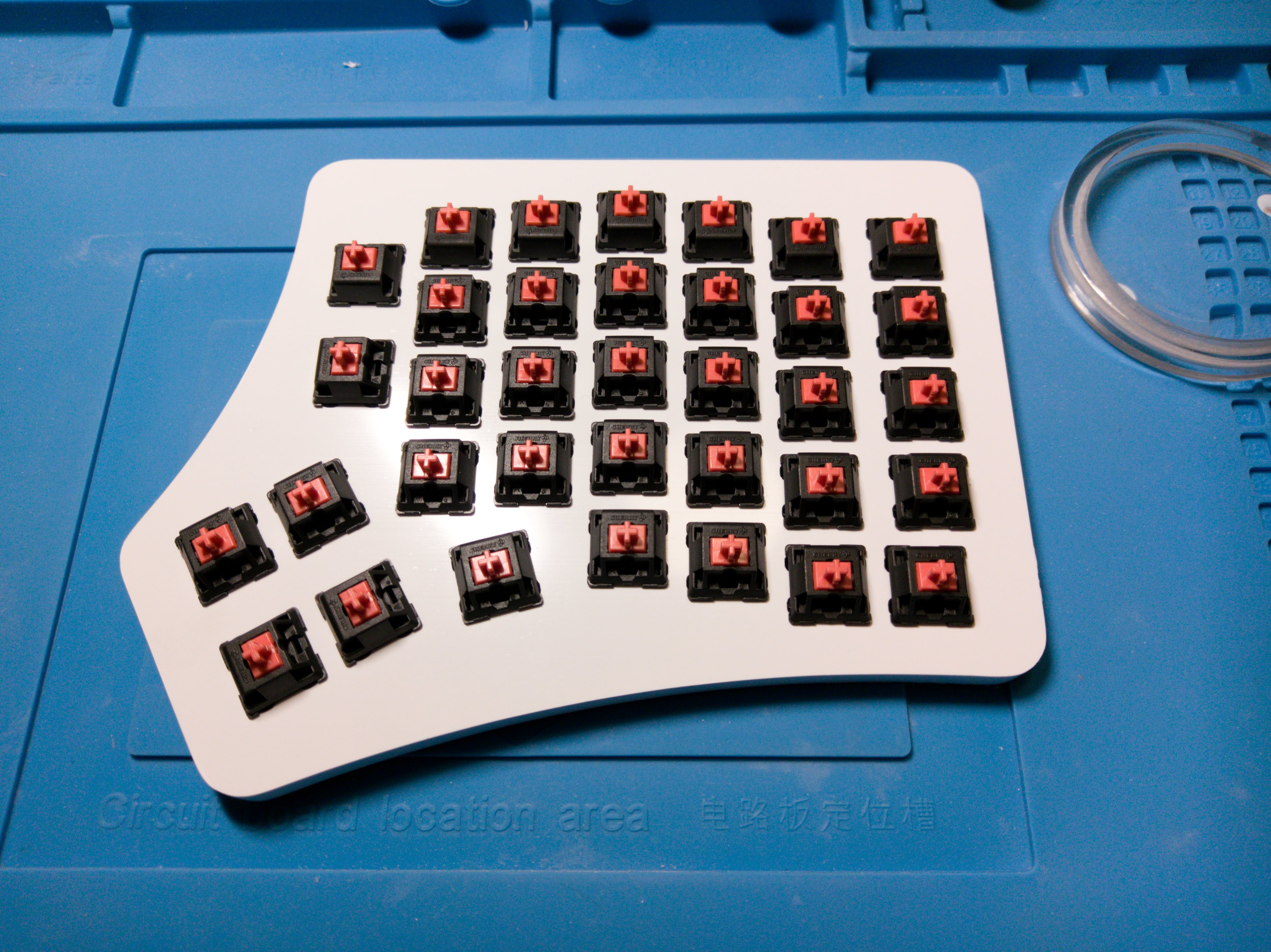
 Rince and repeat.
 Note: the PLA filament is pretty flexible and it's not the best material for a keyboard plate but I tried my best to make it nice to use. I designed the plate to be 4mm thick with a cutout for the plastic stabs in the switches to grip on. I followed the mechanical drawing here:
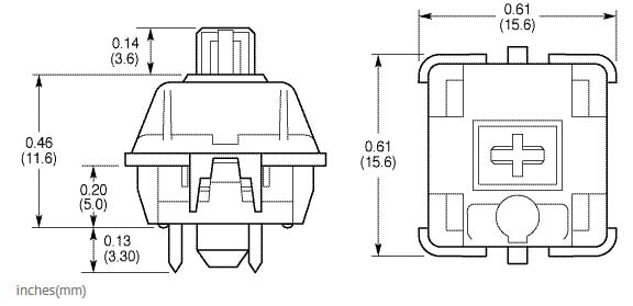

 Perfect fit!
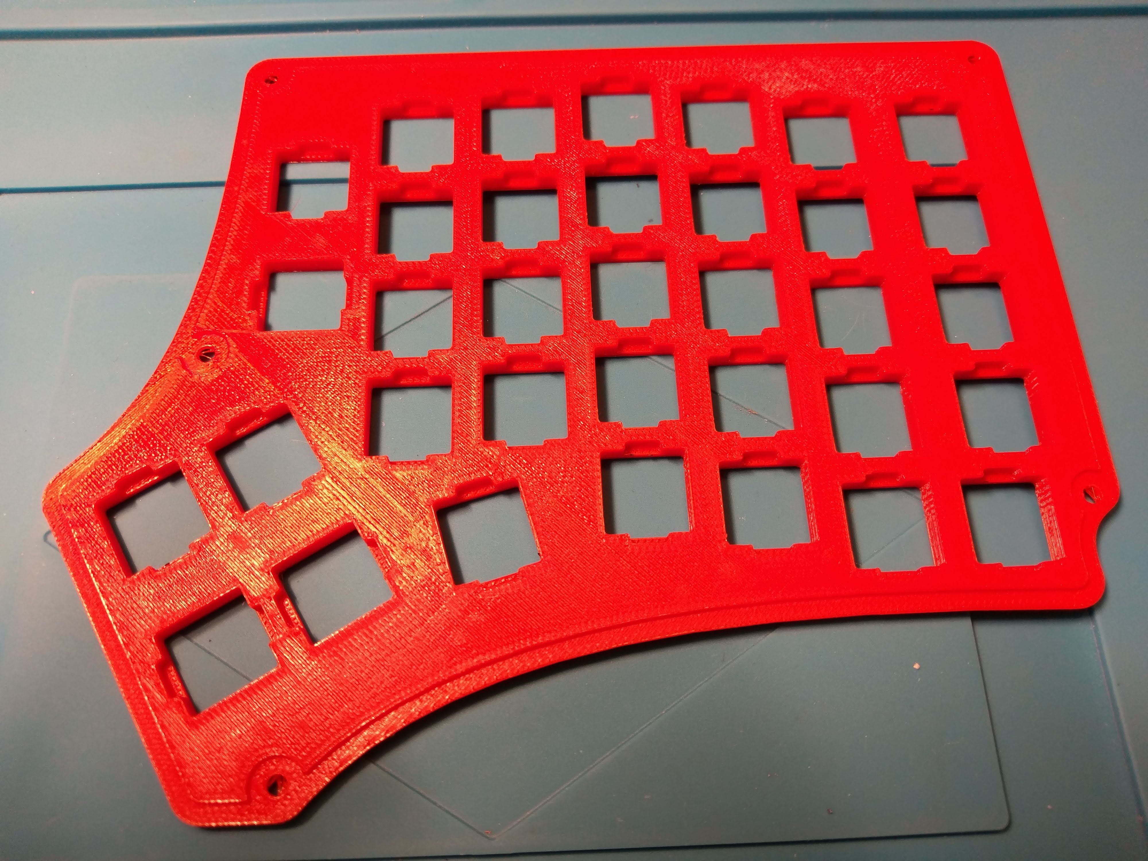
 This plate is great, 4mm is the perfect thickness for it. It doesn't flex and you I didn't take into account the stiffness of the PCB... this went much better than expected!