Mattia Dal Ben
-
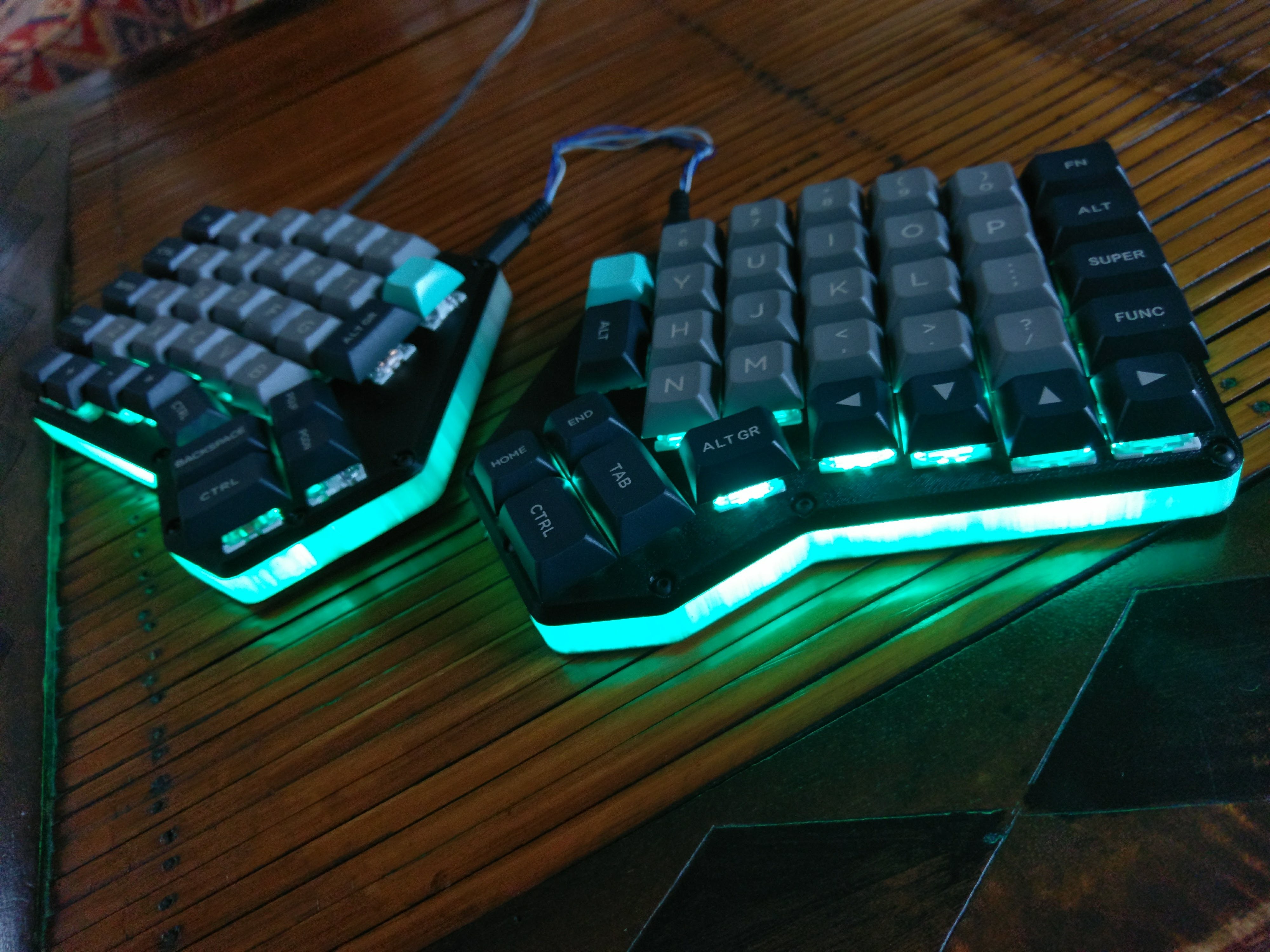
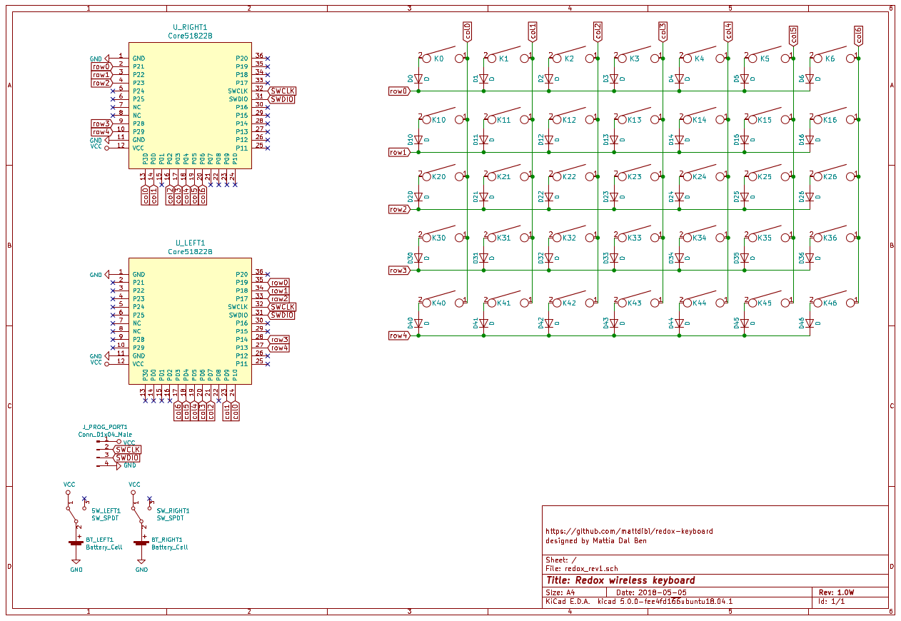
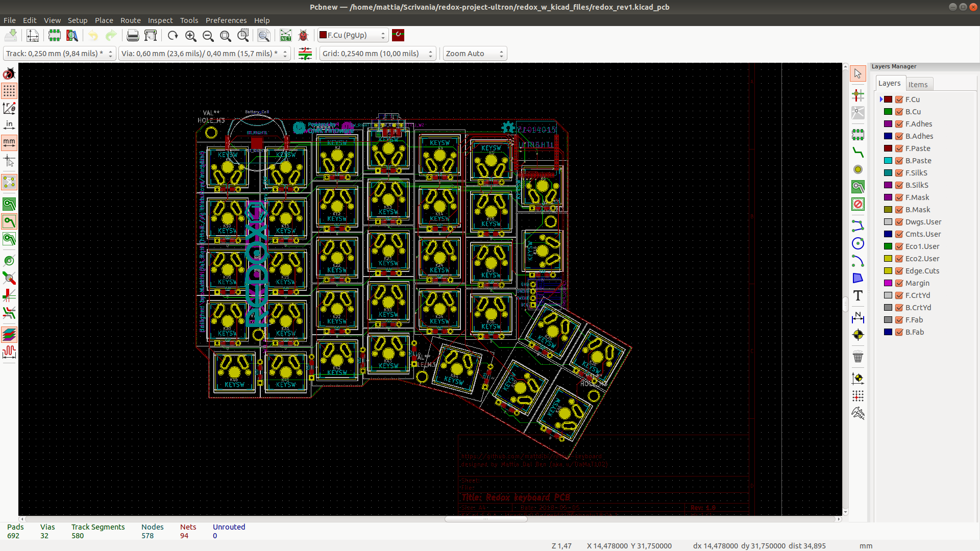
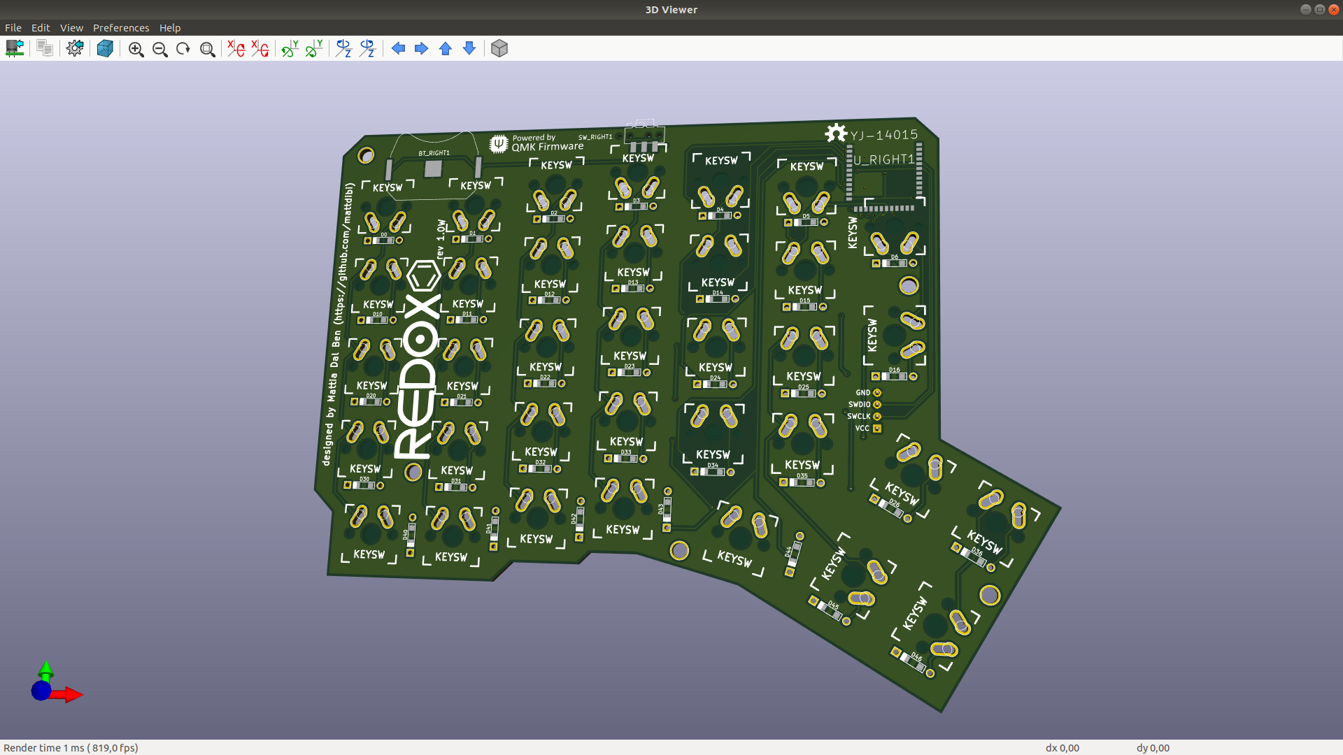
Redox codename Ultron pt.4
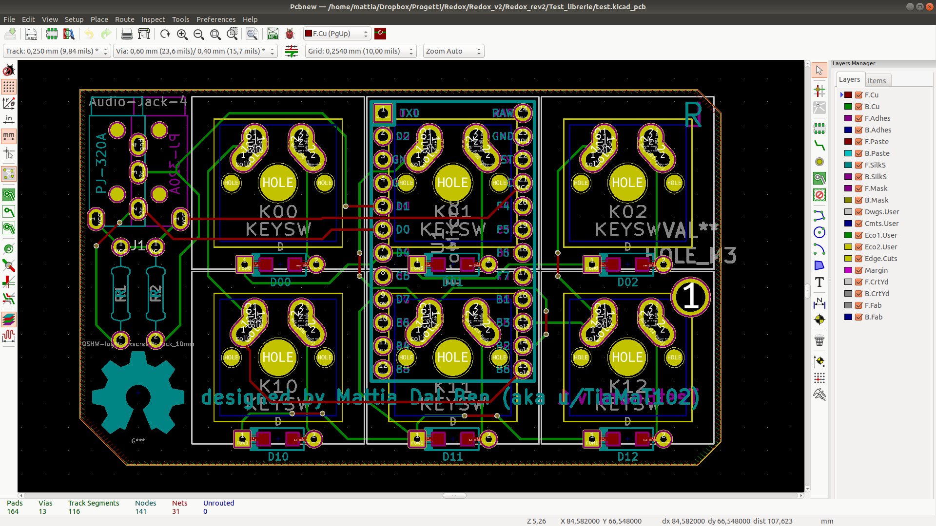
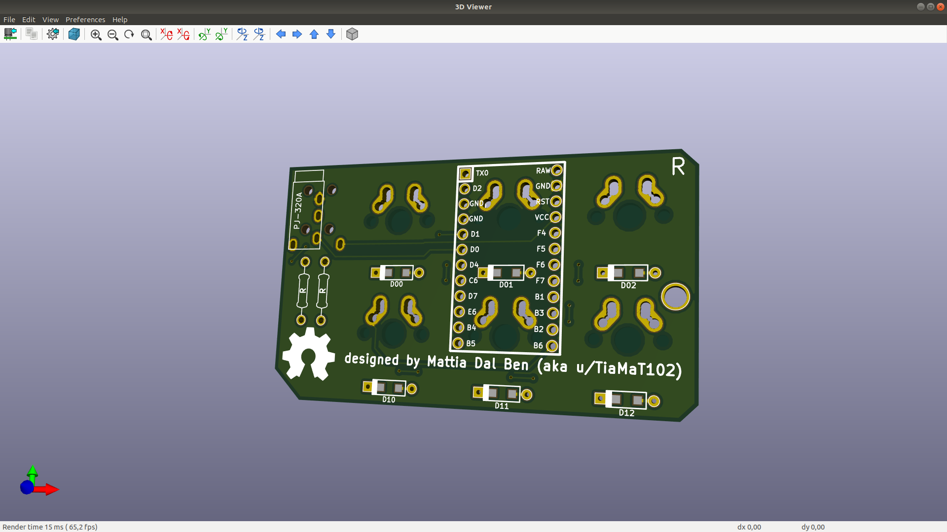
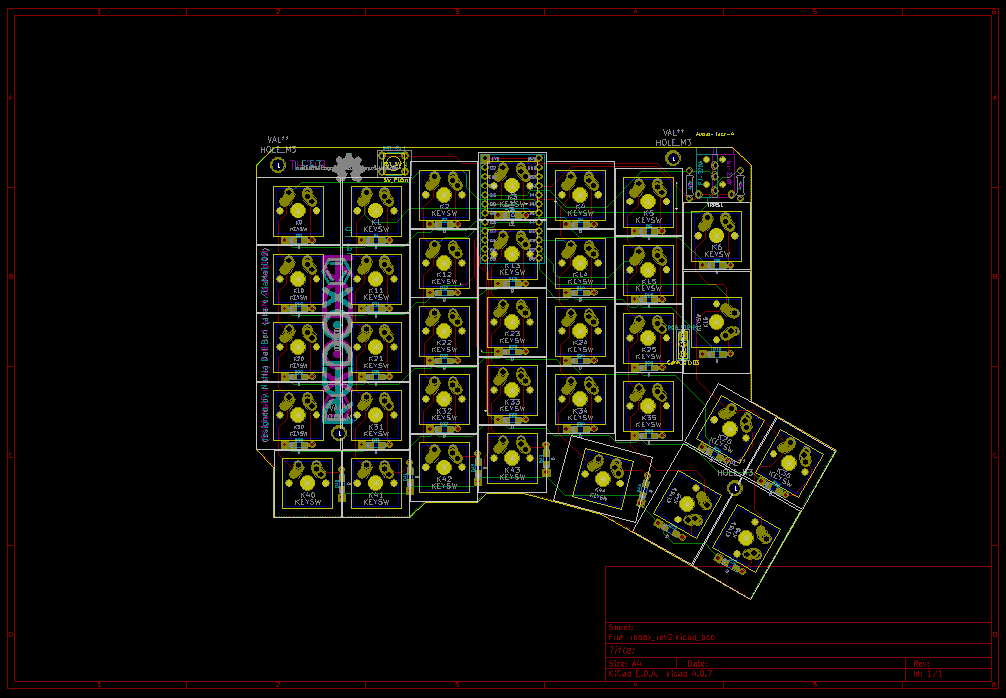
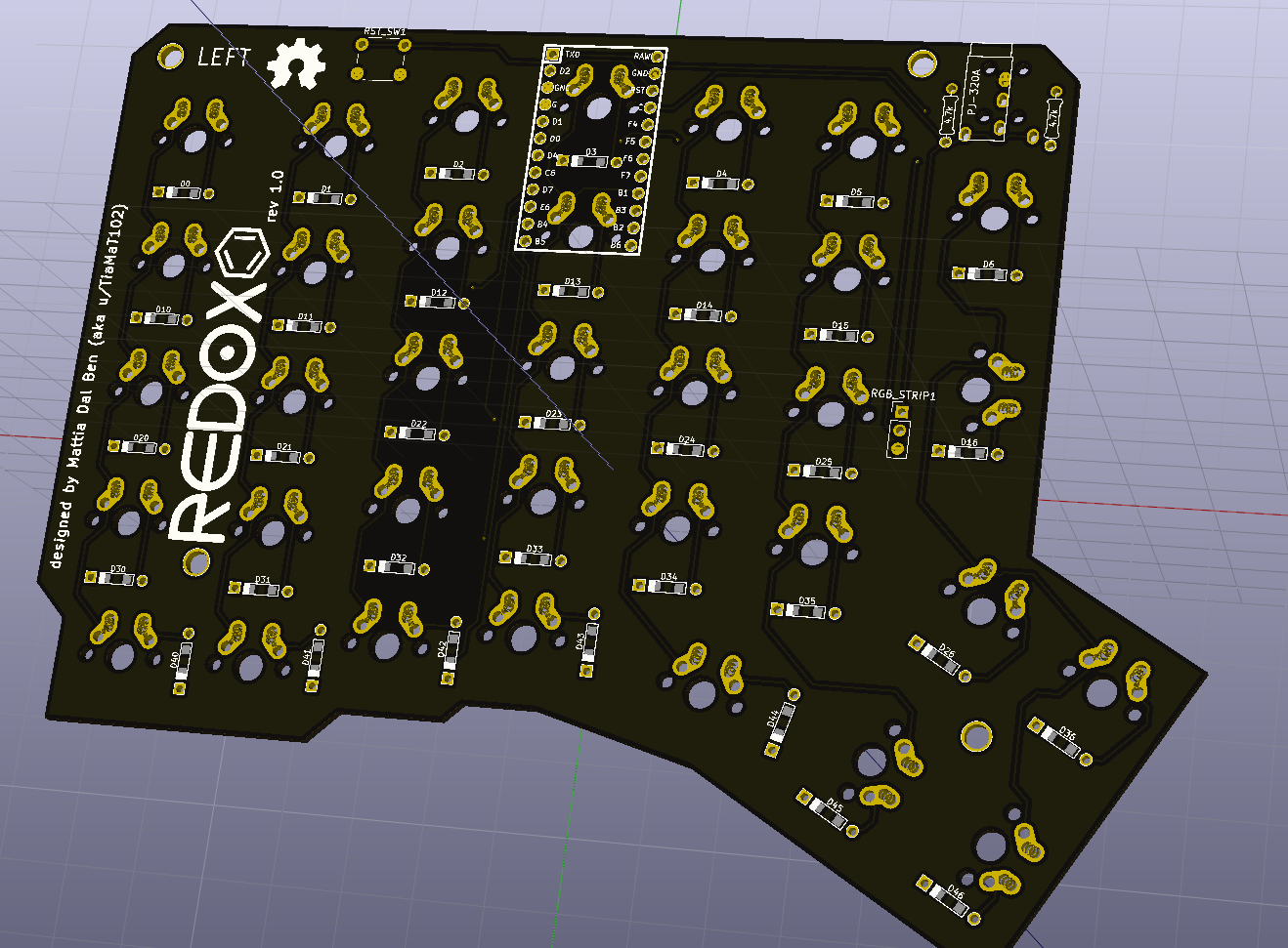
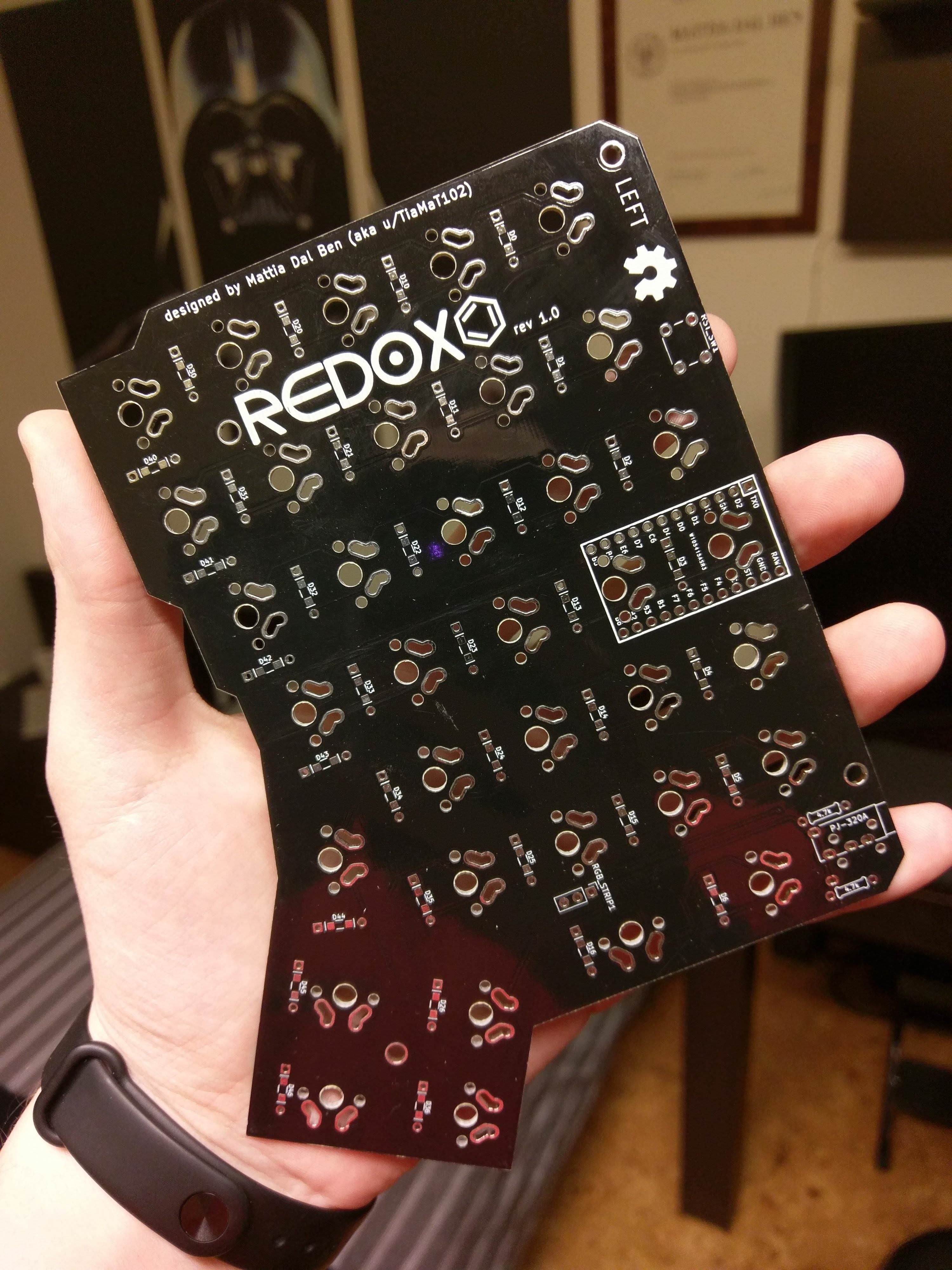
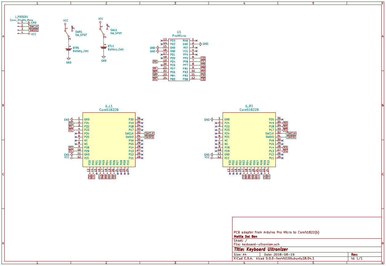
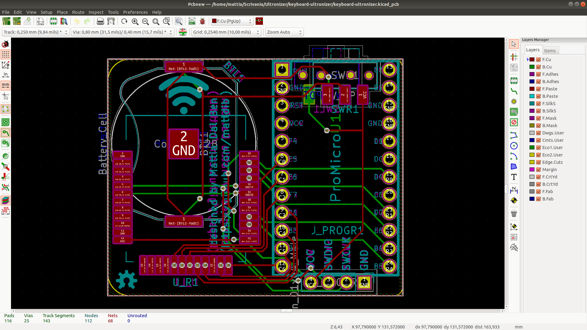
08/26/2018 at 10:06 • 2 commentsPCB ordered!
I'm a little anxious about the nrf51822 module footprint and the battery holder but what is done is done. I used the YJ-14015 module (which is a Core51822 clone) because is smaller than the Core51822(b) and it's a tight fit, but I couldn't find a datasheet online nor some machanical drawing to validate the footprint I have... we'll see.
Here's some pics of the board and schematics.
![]()
![]()
![]()
-
Redox codename Ultron pt.3
08/25/2018 at 08:21 • 0 commentsFirmware's done!
Finally finished working on the firmware.
- Nordic MCU's firmware sources and precompiled binaries can be found here.
- Pro Micro firmware (QMK based) sources can be found here.
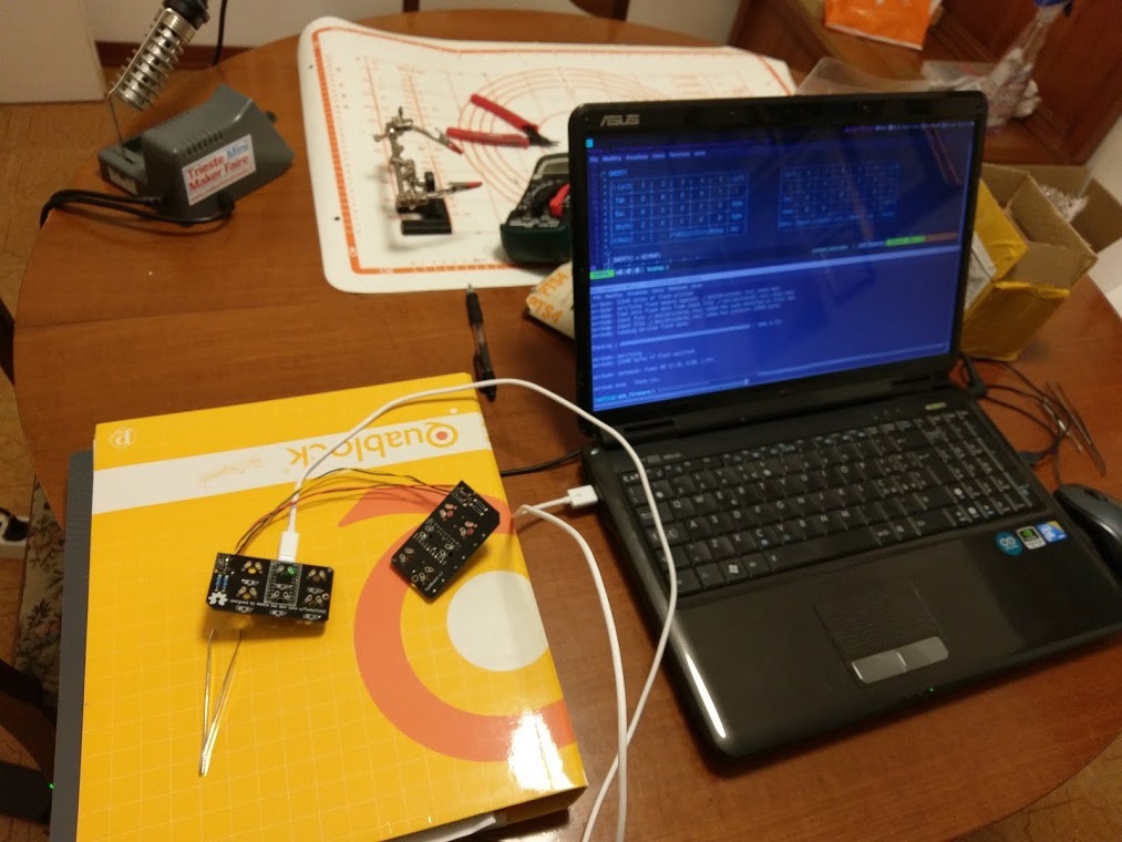
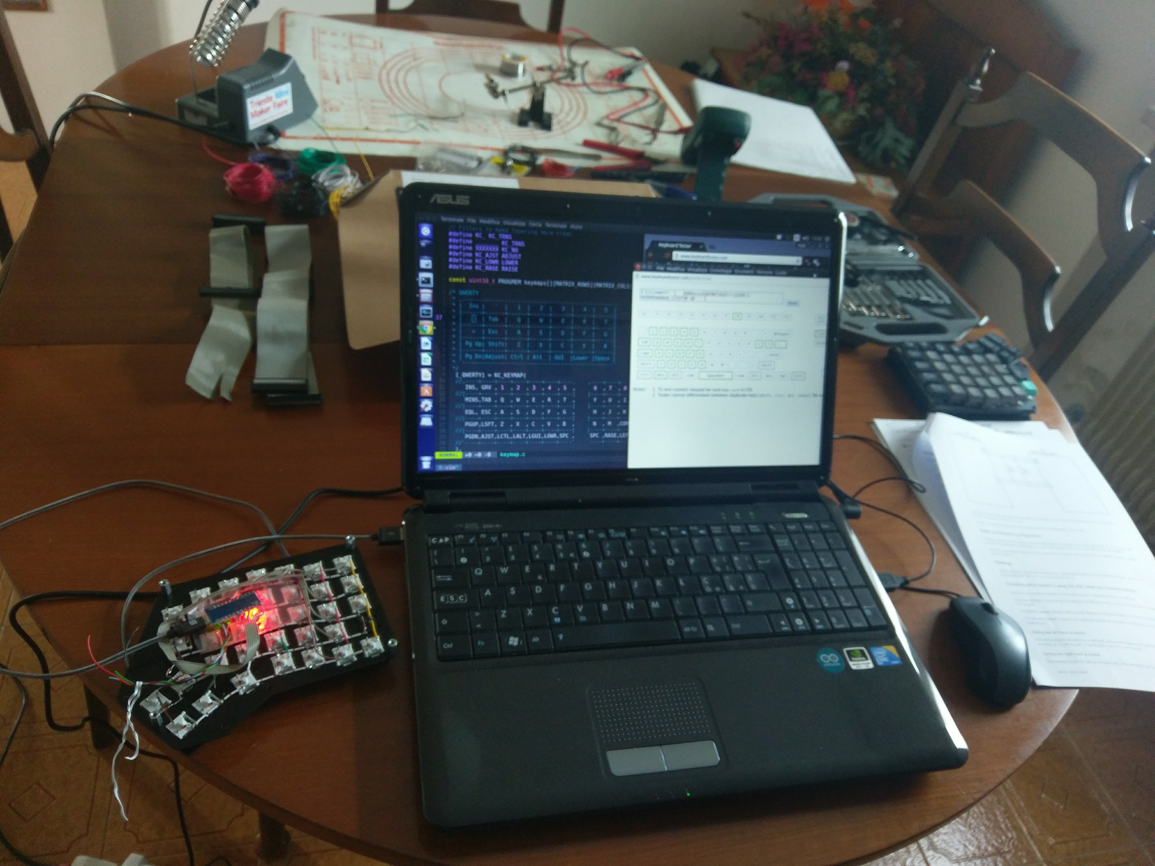
Here's some footage:
![]()
On the right you can see the receiver that's plugged in to the computer. It uses a Pro Micro to run the QMK firmware which interrogates through UART the Core51822 for the state of the matrix. The Core51822 module communicates over Gazell protocol to the left and right hands of the keyboard. These two scan the matrix for keypresses and send keypresses data to the receiver.
I'm using the tweezers to short-circuit the switch pads to simulate a keypress.
Now is time for some sweet sweet PCB design...
-
Redox codename Ultron pt.2
08/22/2018 at 19:41 • 0 commentsIT'S ALIVE!
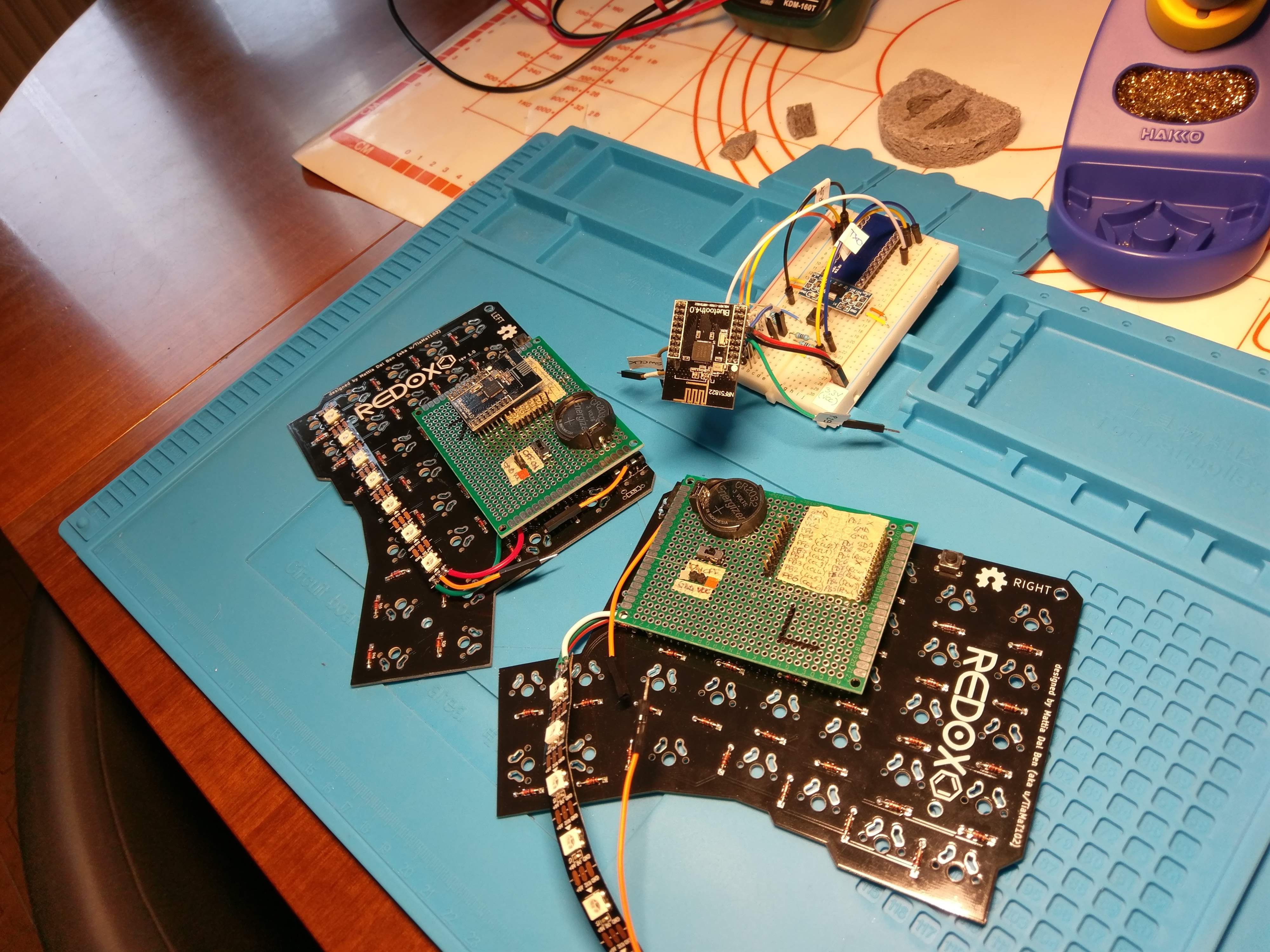
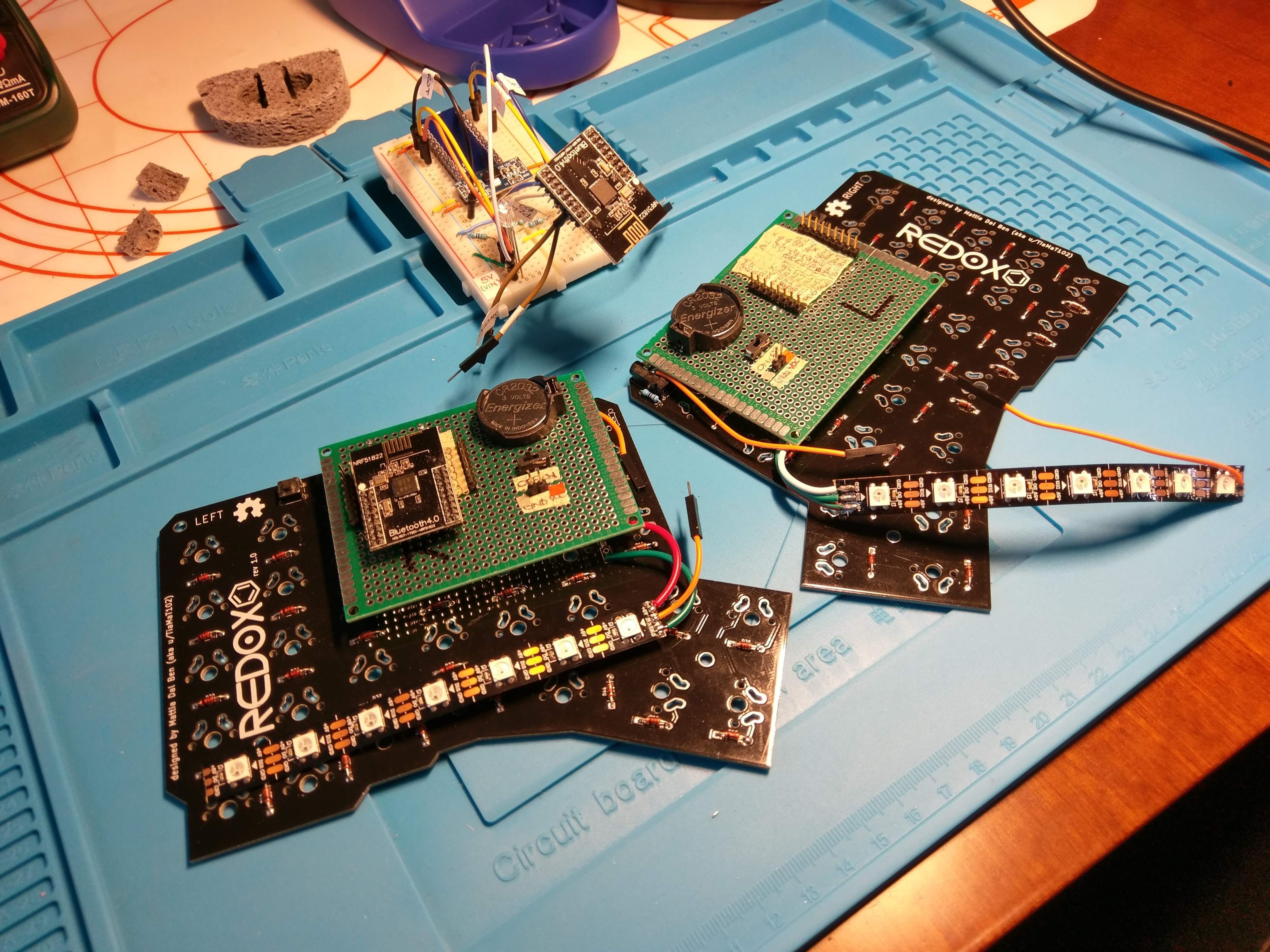
Today I finally received the jumper cables. I hacked through the Mitosis and Interphase source code and came up with a sort-of-working firmware to test everything.
After a few minor initial problem (might have set the wrong addresses) I made it work.
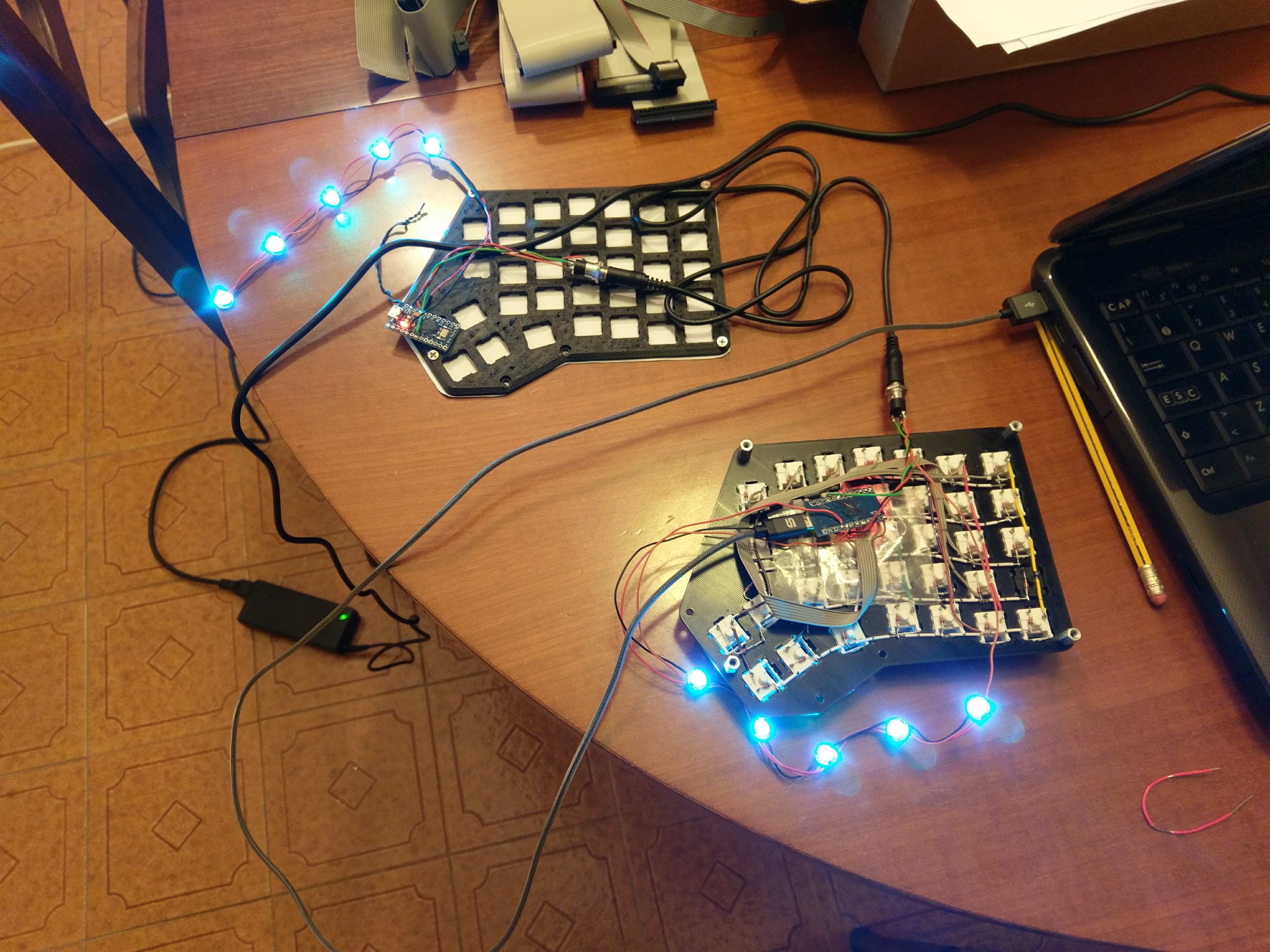
I programmed and then wired the Core51822 module to the keyboard matrix, it successfully scans the matrix and sends data to the receiver.
![]()
![]()
![]()
Here's some footage of the keyboard working.
![]()
I plan to write a proper firmware in the following days, design the PCB and manufacture it. I'm really looking forward to it!
-
Redox Ultronizer
08/21/2018 at 10:03 • 4 commentsSince I got bored waiting for the adapter cables to arrive I started designing an adapter board for the Core51822(b) module to Arduino Pro Micro footprint.
Its main goal is to replicate what I achived using the perfboard using a proper PCB. I then realized that, with some adjusting, it might be used to give wireless functionalities to most of the open-source split keyboard I know of ( Iris, Zen, Let's split, etc.).
As usual here comes some PCB eye-candy:
![]()
![]()
![]()
![]()
I had some problems making this a double-side PCB but I am sufficiently confident it should work. Obviously the CR2032 receptacle needs to be mounted on the top and the Core51822 on the bottom of the board. Also some electrical tape might be needed to prevent shorts on the Core51822 pads for when the battery will be in place.
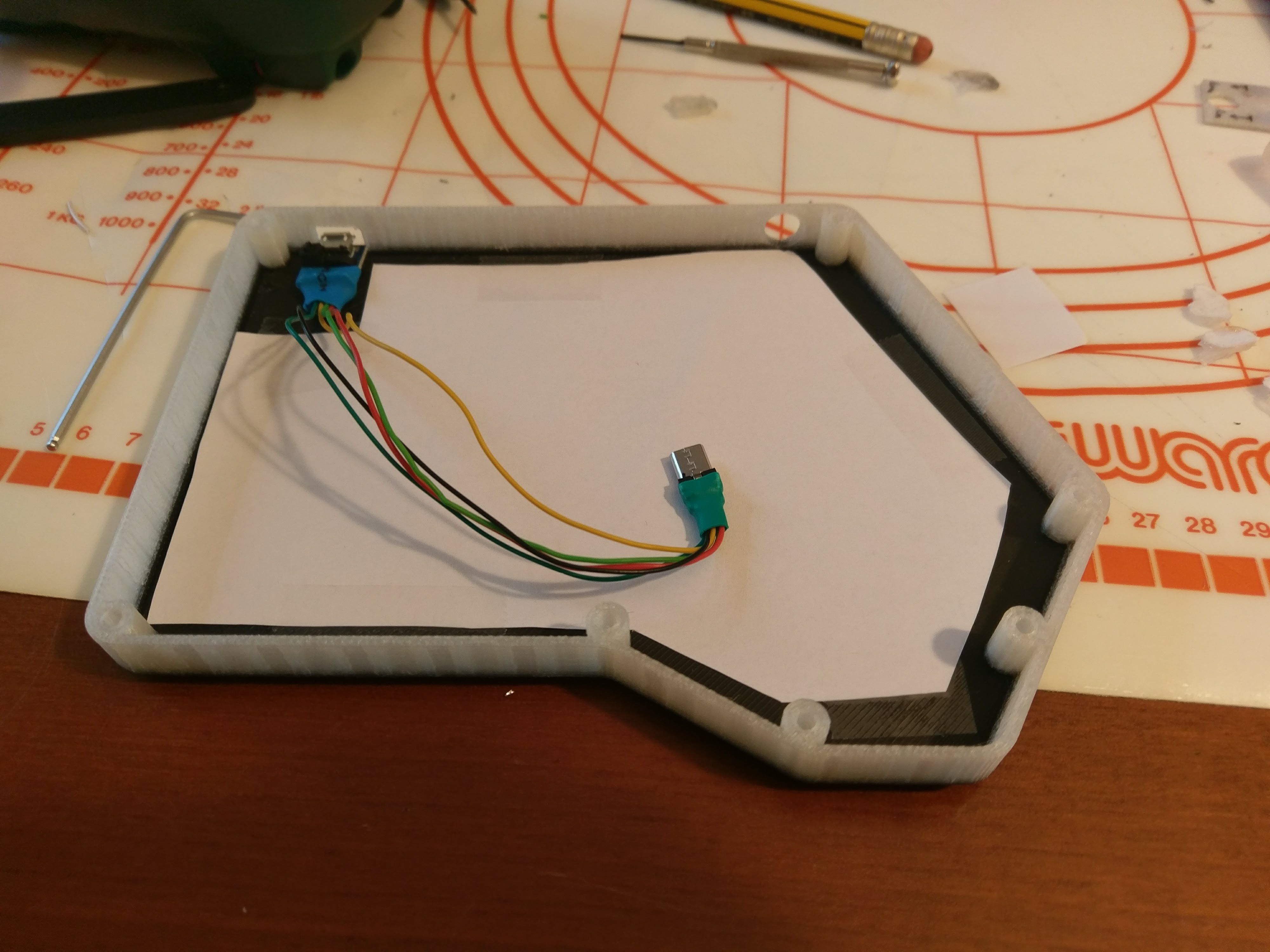
The main switch should be easily reachable since it is placed where the USB port should be.
After some more work (mainly to make it more general-purpose) I'll manufacture these and see if this fits my needs.
-
Redox codename Ultron pt.1
08/20/2018 at 20:57 • 0 comments"There are no strings on me..."
It's now almost a year that I'm working on and off on the Redox project, however I keep asking myself: "How can I improve this design further?".
"Wireless" is the answer.
In the last few months I began researching how to make a split QMK-compatible keyboard wireless and the only answer was the Core51822(b) module (see the Mitosis for further details. On a side note: that keyboard is awesome!). Needless to say I ordered a few immediately and began experimenting.
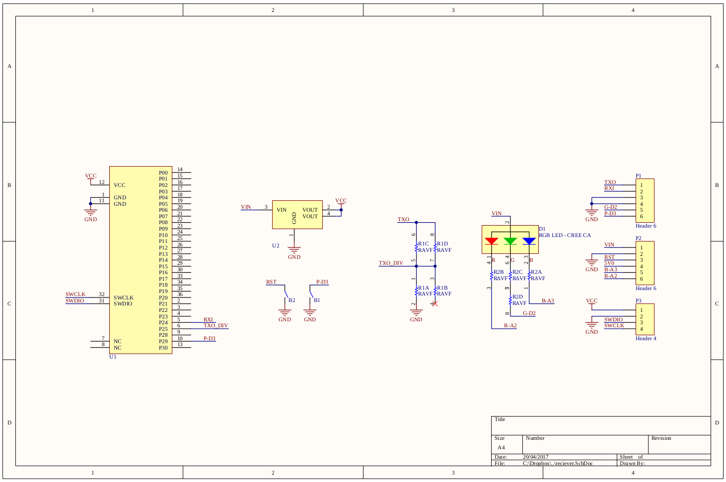
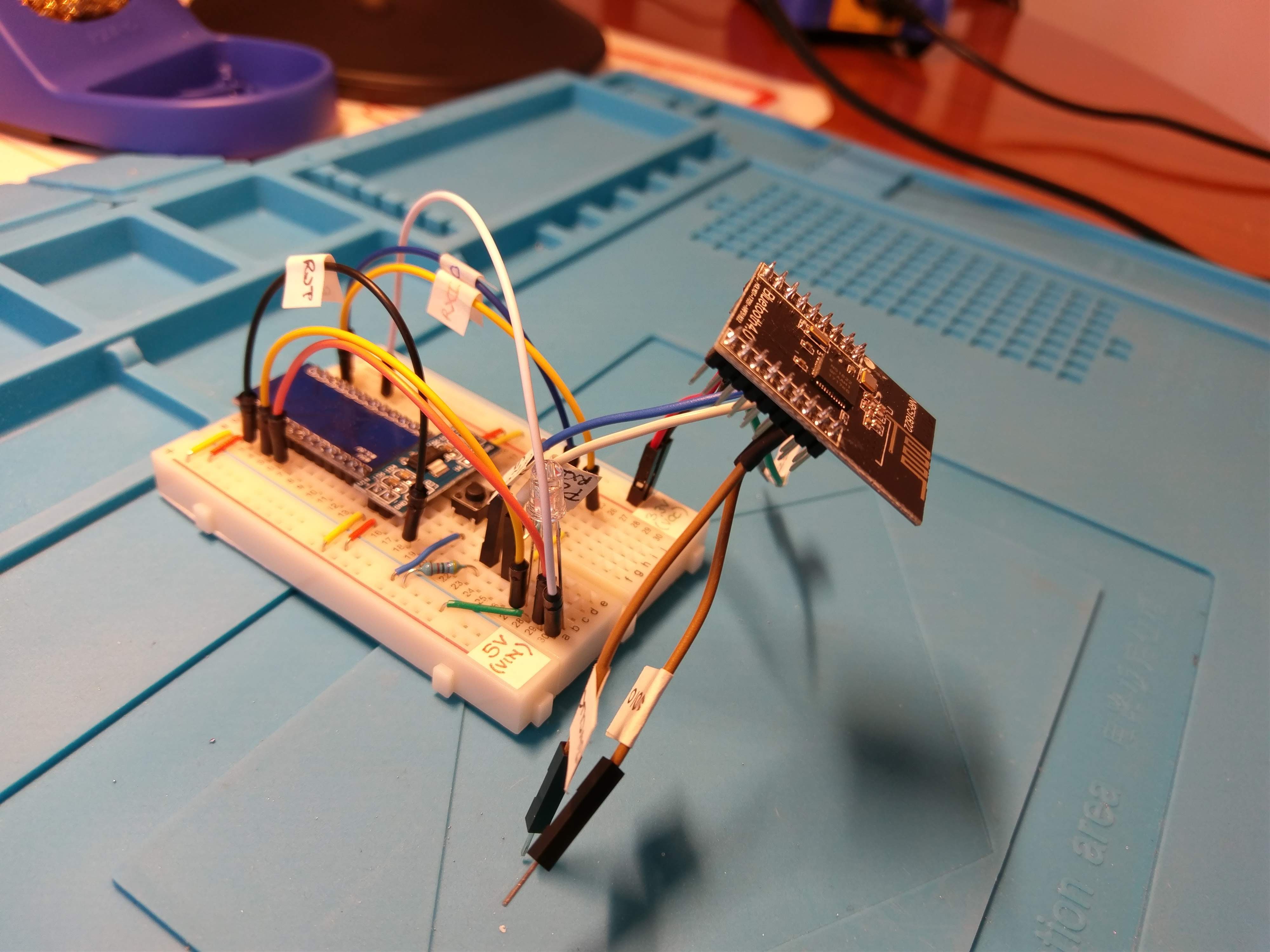
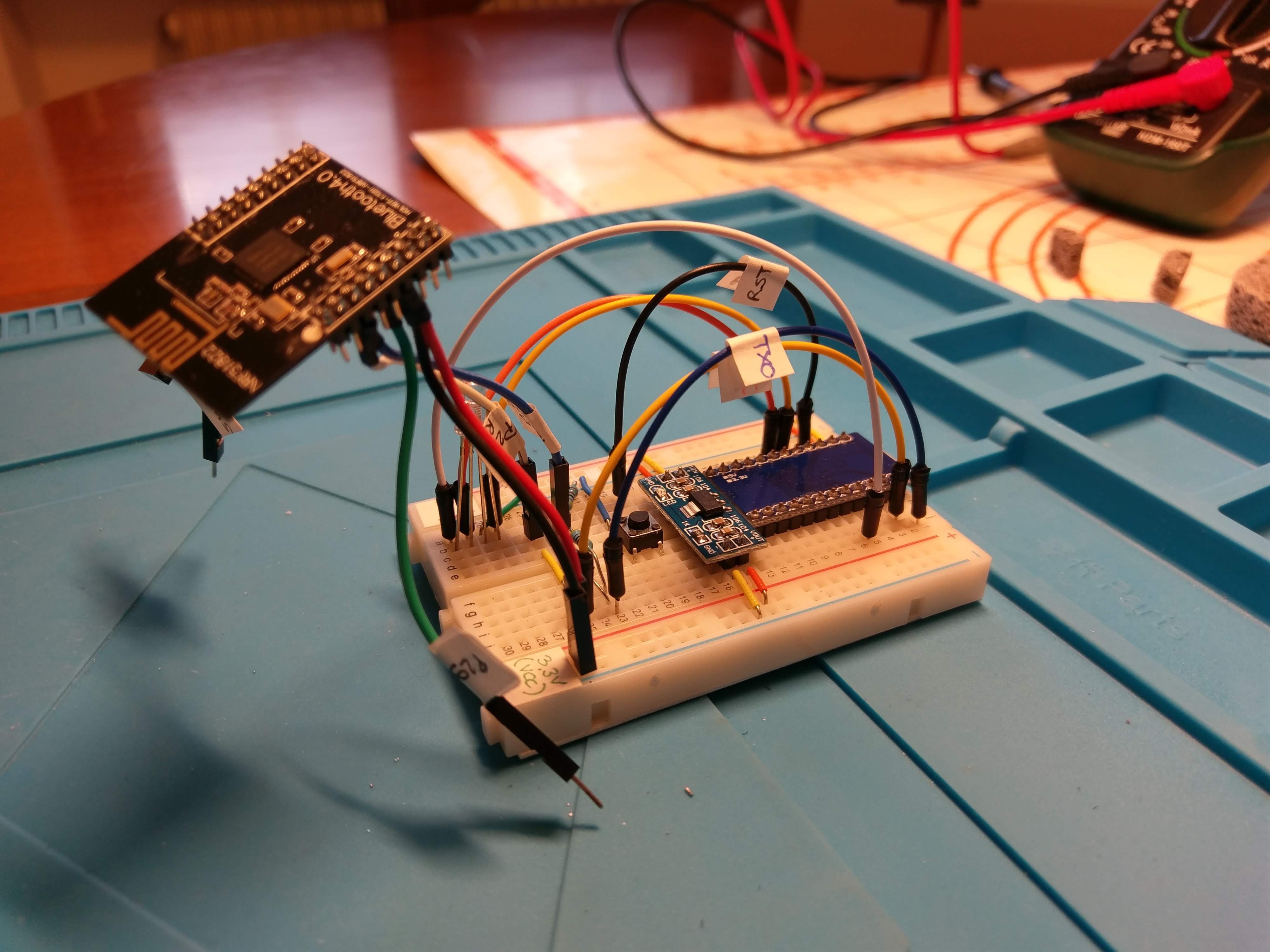
ReceiverI began by replicating the receiver module using the available schematics from the Mitosis project.
![]()
I used a breadboard compatible version of the AMS1117 3.3 voltage regulator to power the Core51822 and for the remaining parts I used through-hole components I had laying around. I then realized the main drawback of using the Core51822: those damn 2.0mm pitch headers. I got a little creative with the hand soldering but for the keyboard matrix wiring I'll use some 2.0mm pitch to 2.54mm pitch jumpers I found on Amazon.
![]()
![]()
I then tested that everything was working with the usual led blink. To get to this point I used this excellent guide for the NRF51822.
![]()
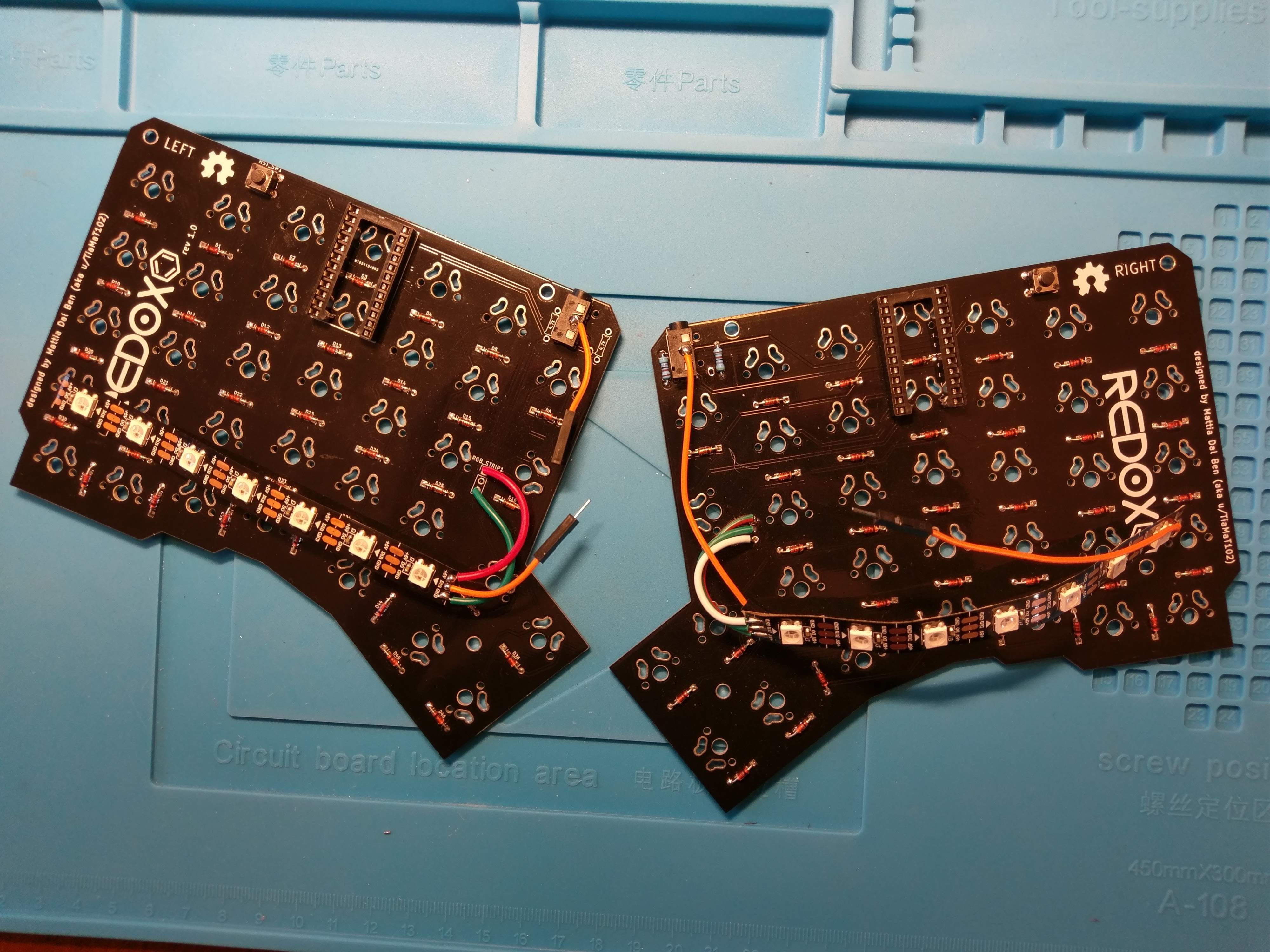
Now it was time to wire the keyboard.
Transmitters
Since this is just a proof-of-concept I wanted to recycle my testing board before designing a new PCB from the ground up.
![]()
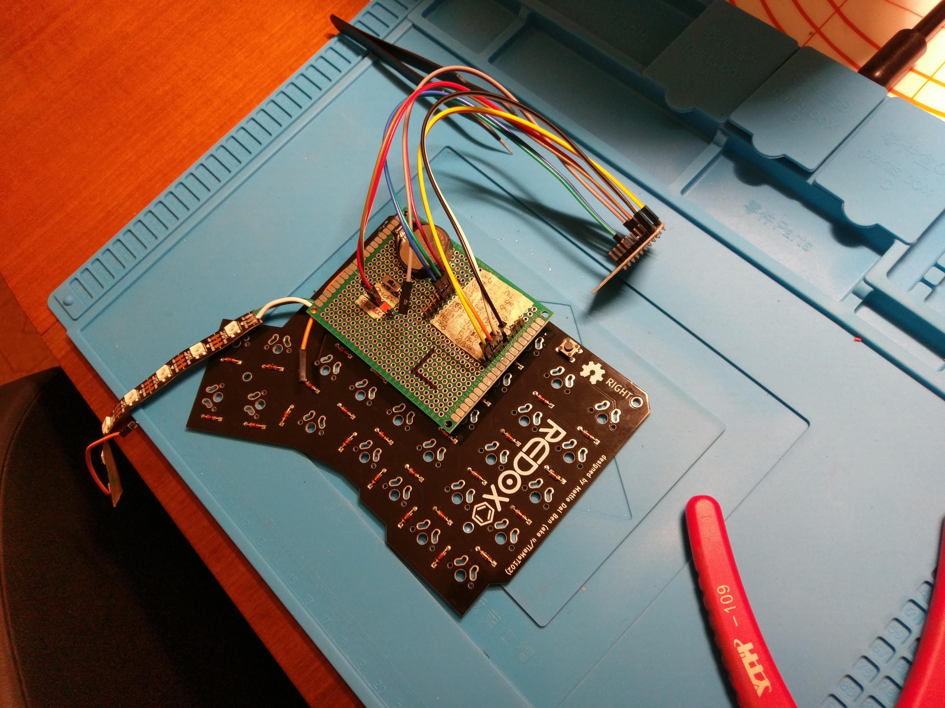
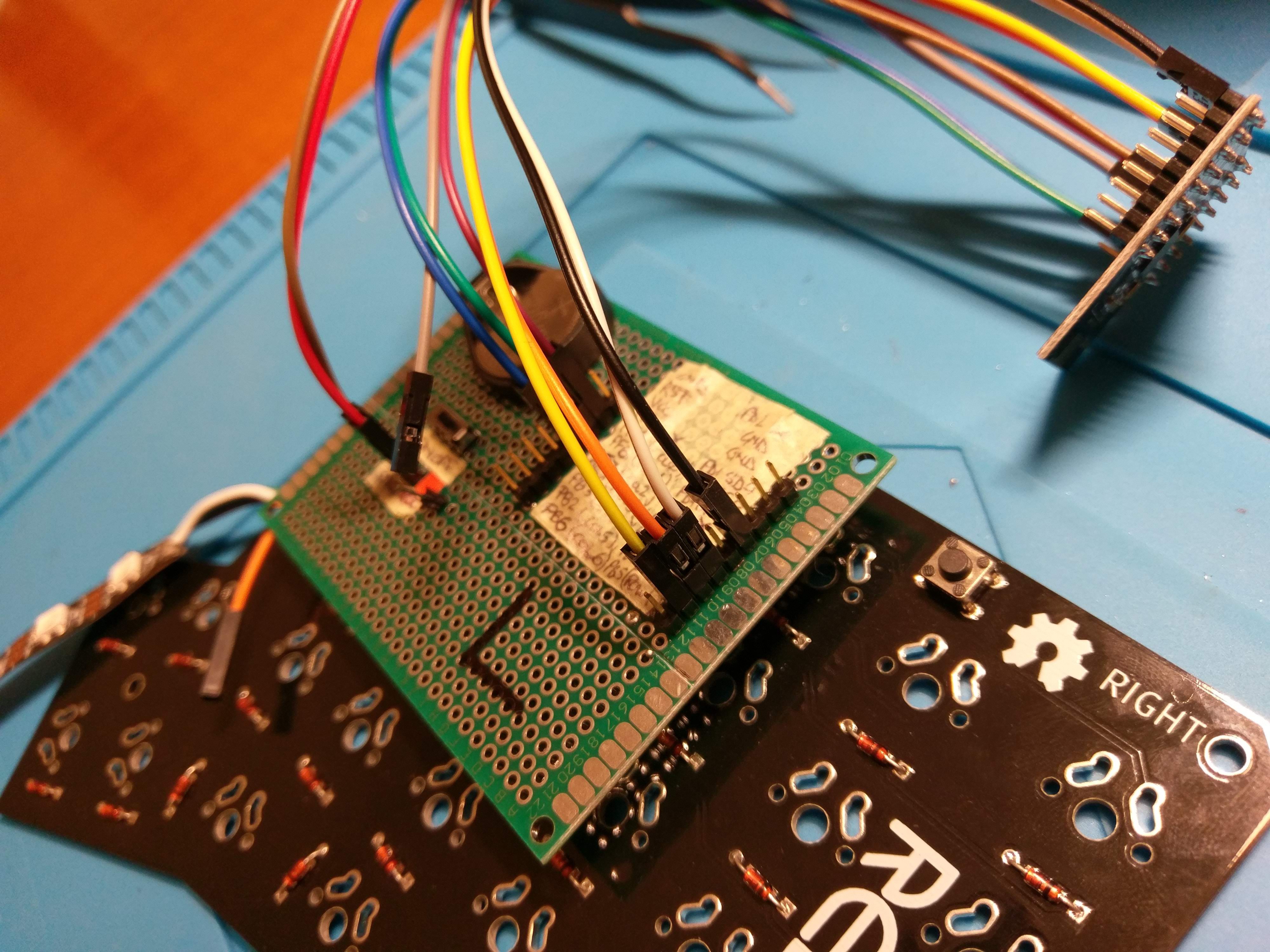
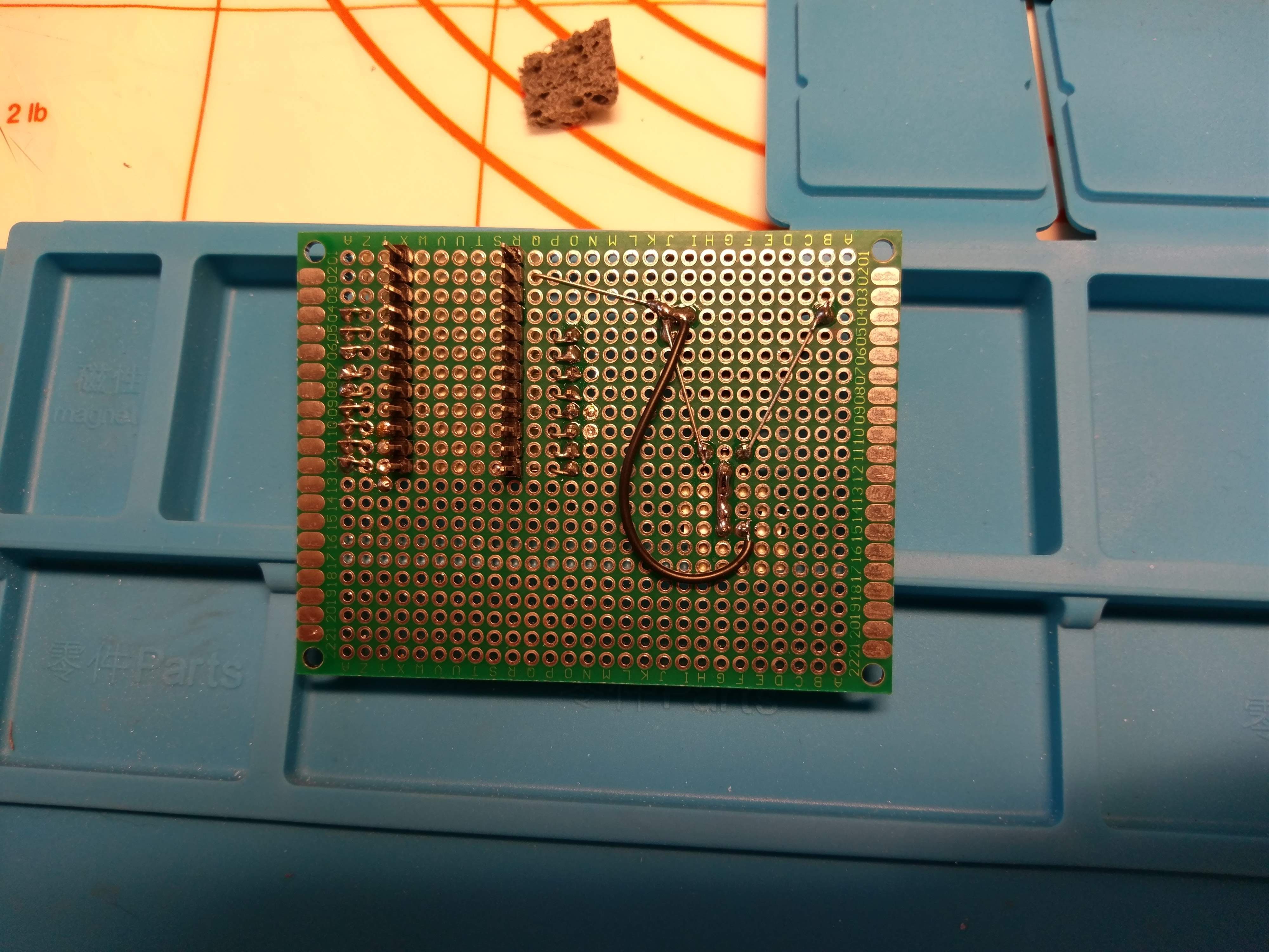
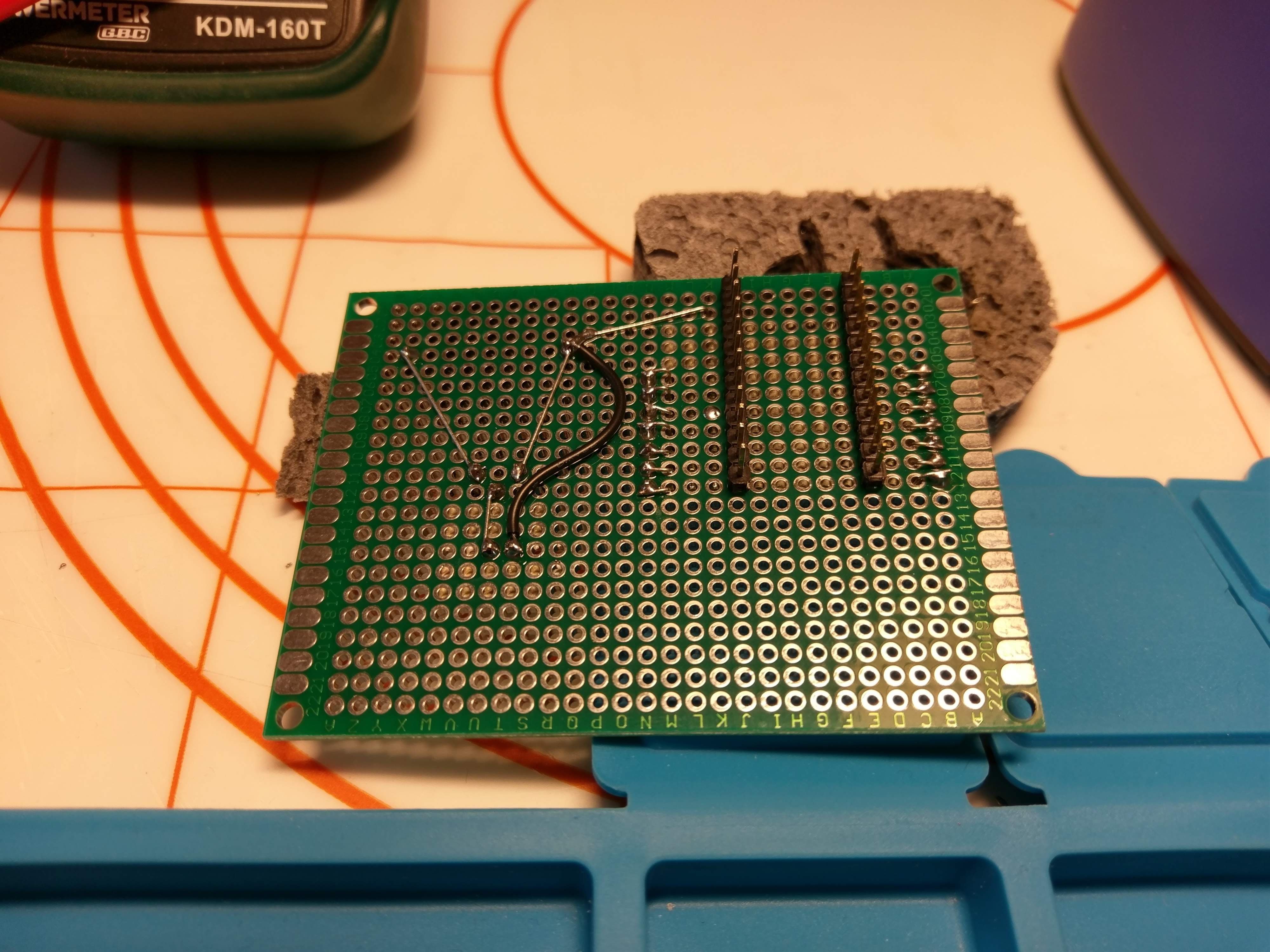
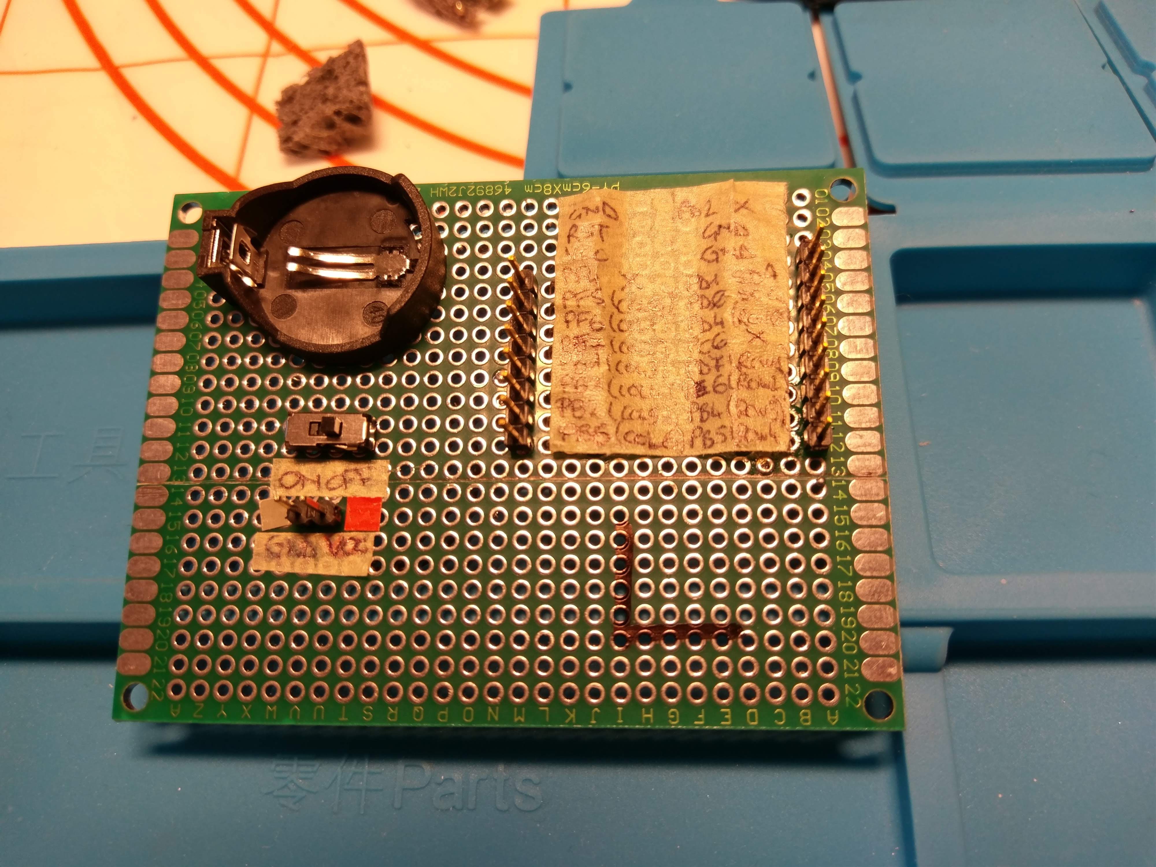
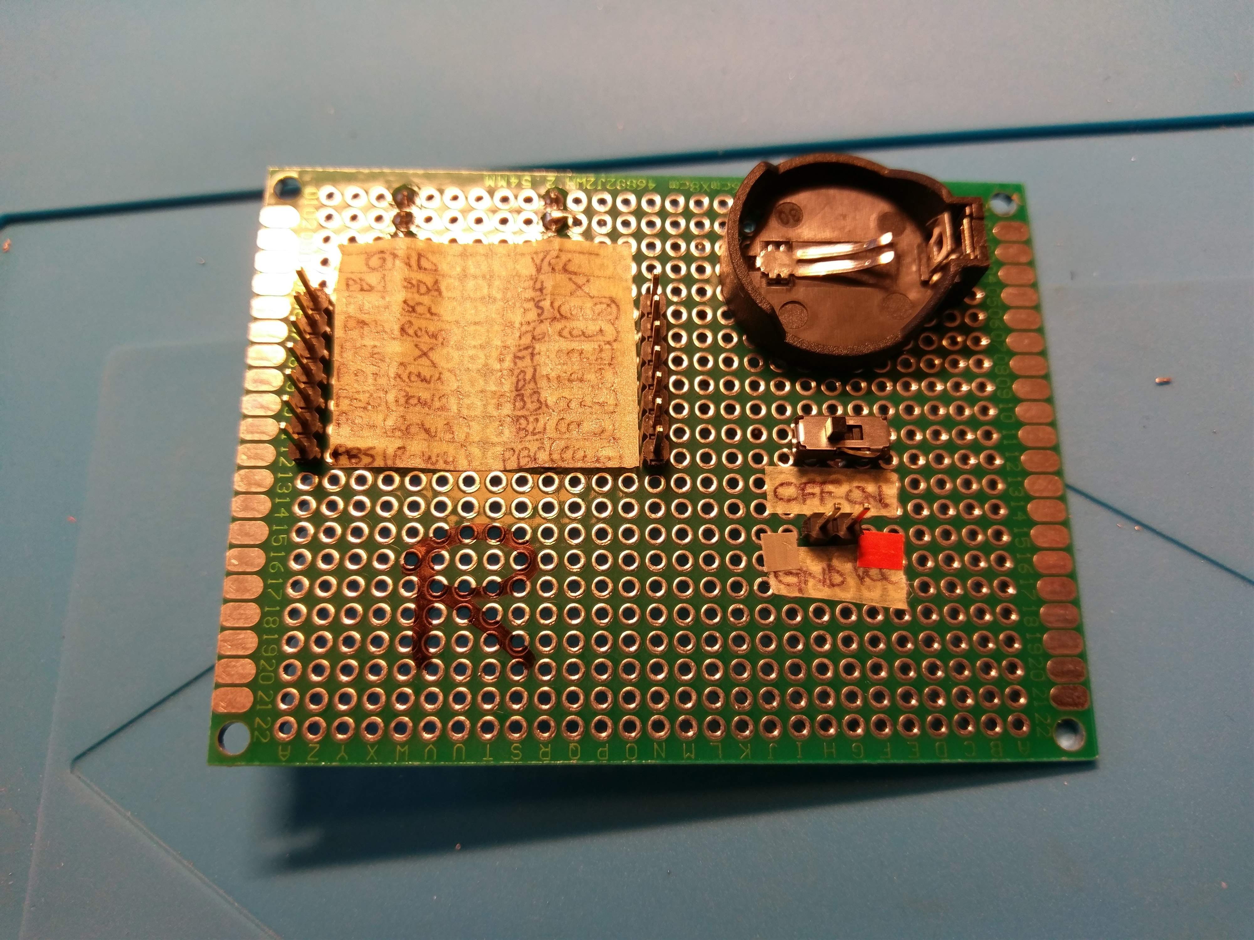
I then decided to create a sort of adapter for the Arduino Pro Micro to something that can be wired to the Core51822. I came up with the following:
![]()
![]()
![]()
![]()
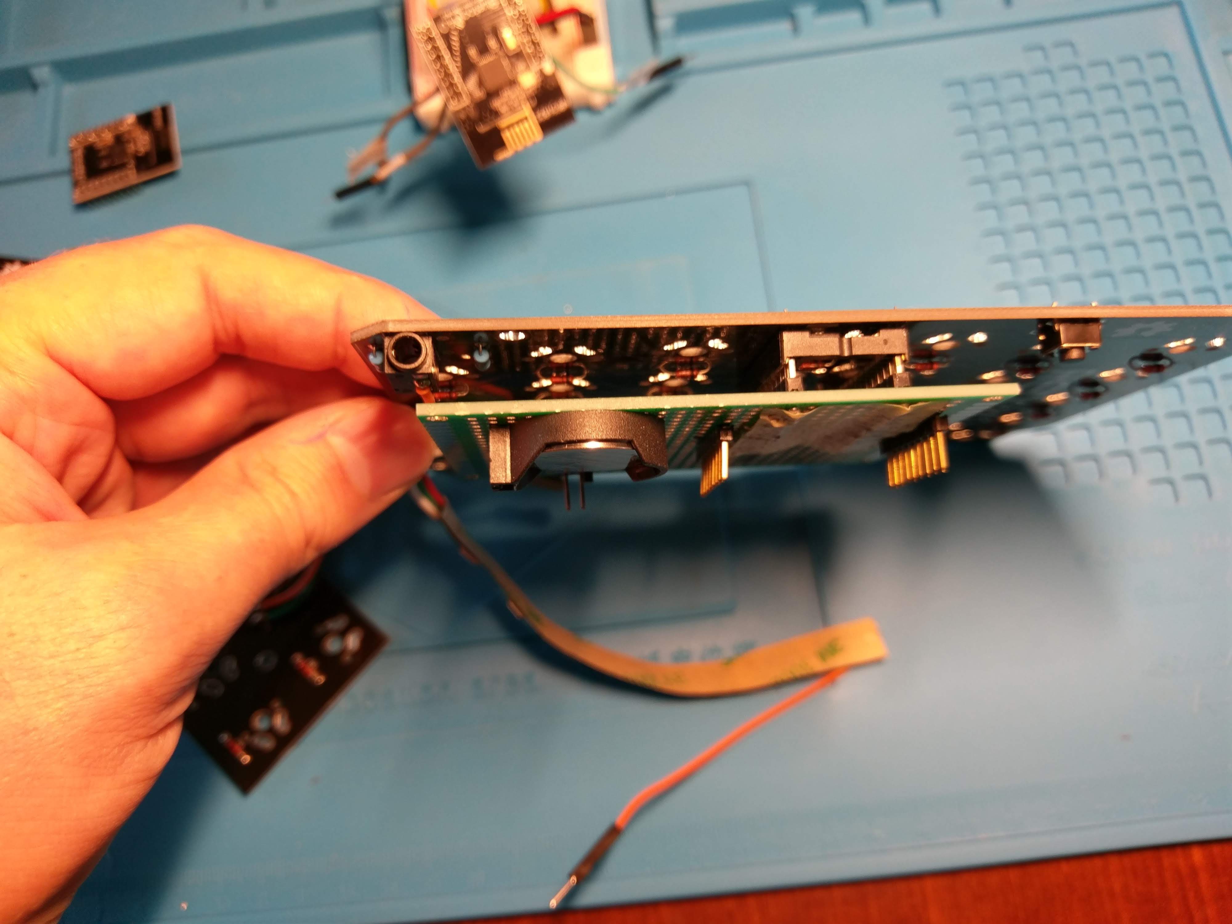
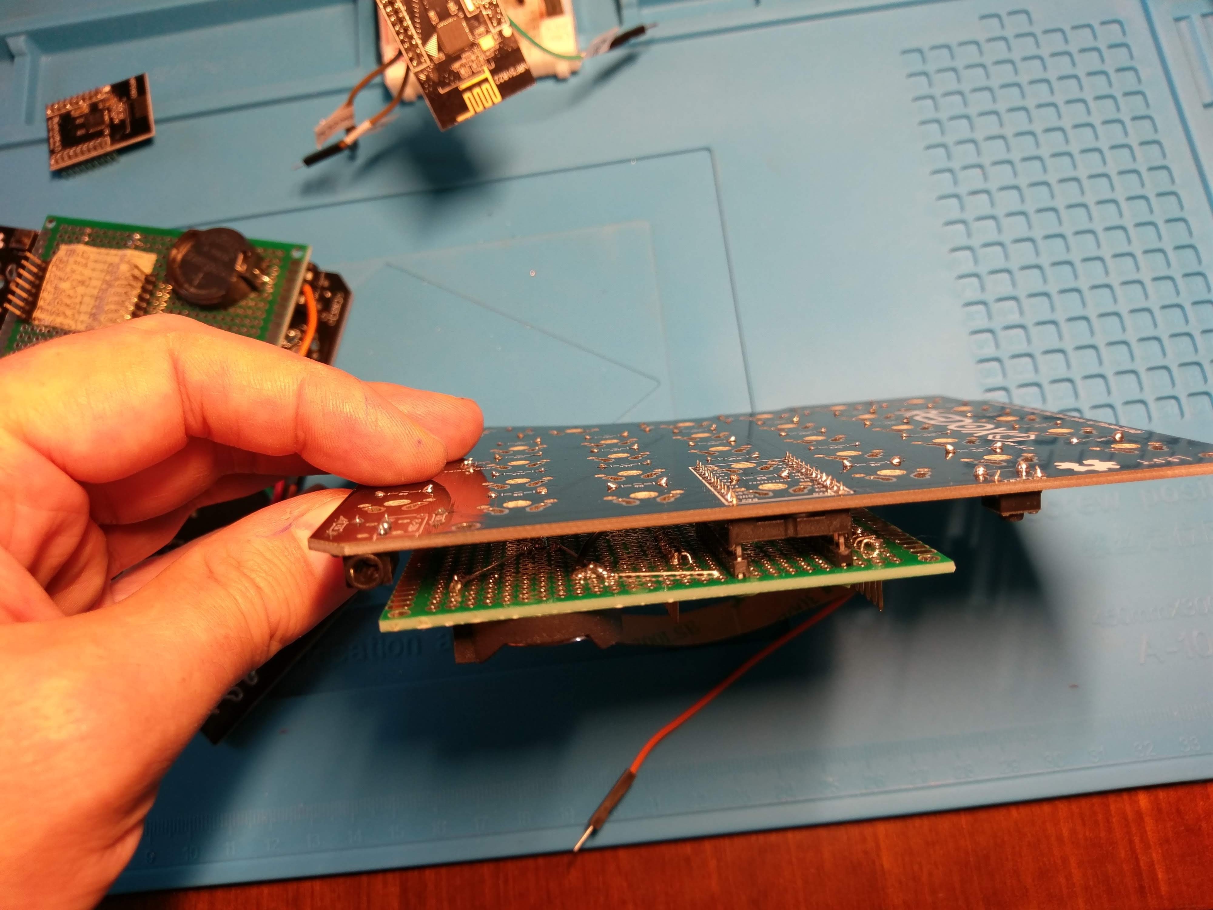
I have a pin header row that fits inside the Pro Micro footprint, those pin are then wired to another row of pin headers that will be connected to the Core51822. I used a CR2032 to power the module.
![]()
![]()
![]()
![]() I am now waiting for the jumper cable to arrive to finally get writing some code. Once I get everything to work I'll begin designing the new PCB... my main goal is to make them compatible with the existing cases but I think this will not be an easy task.
I am now waiting for the jumper cable to arrive to finally get writing some code. Once I get everything to work I'll begin designing the new PCB... my main goal is to make them compatible with the existing cases but I think this will not be an easy task. -
Redox rev.1
08/20/2018 at 20:00 • 0 commentsAfter finishing my handwire I began using my keyboard at work. I started loving it so much that I decided I wanted it to become a real thing, not only a handwired prototype, hence the Redox rev.1.
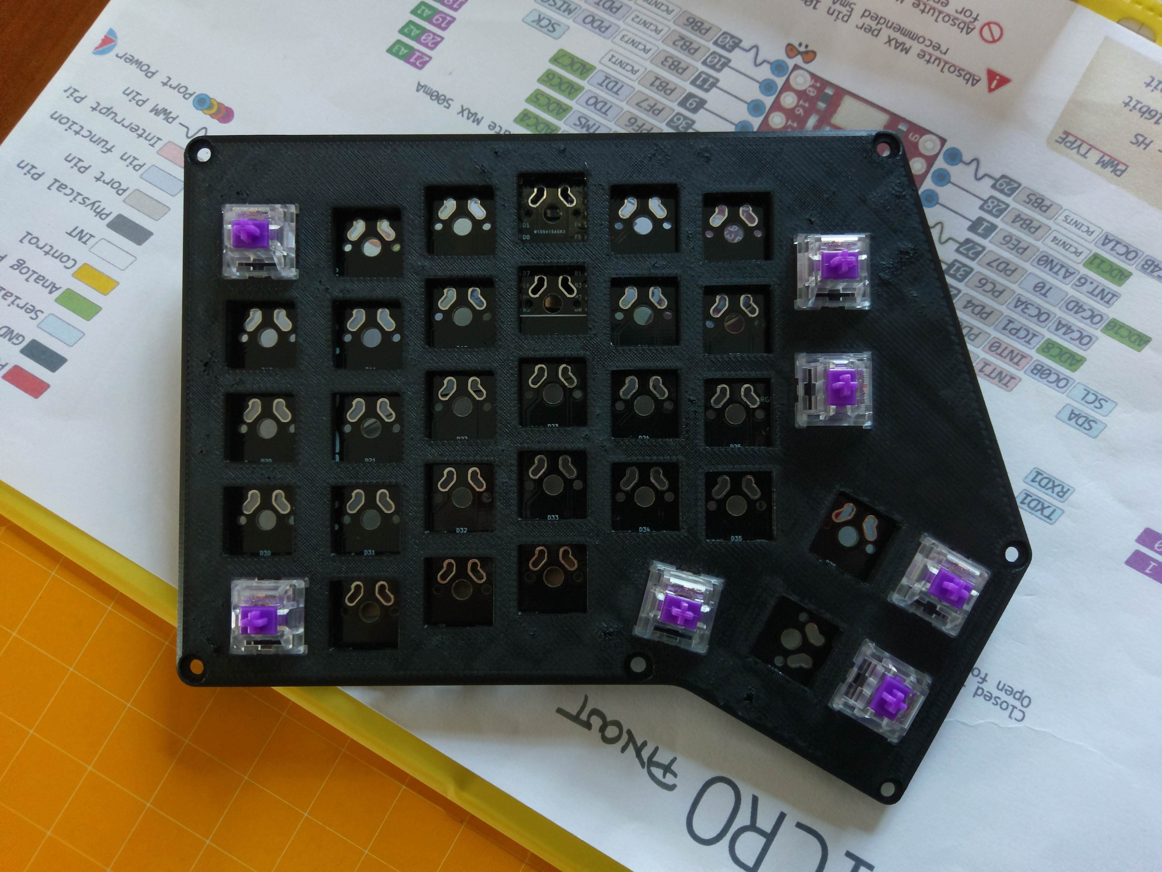
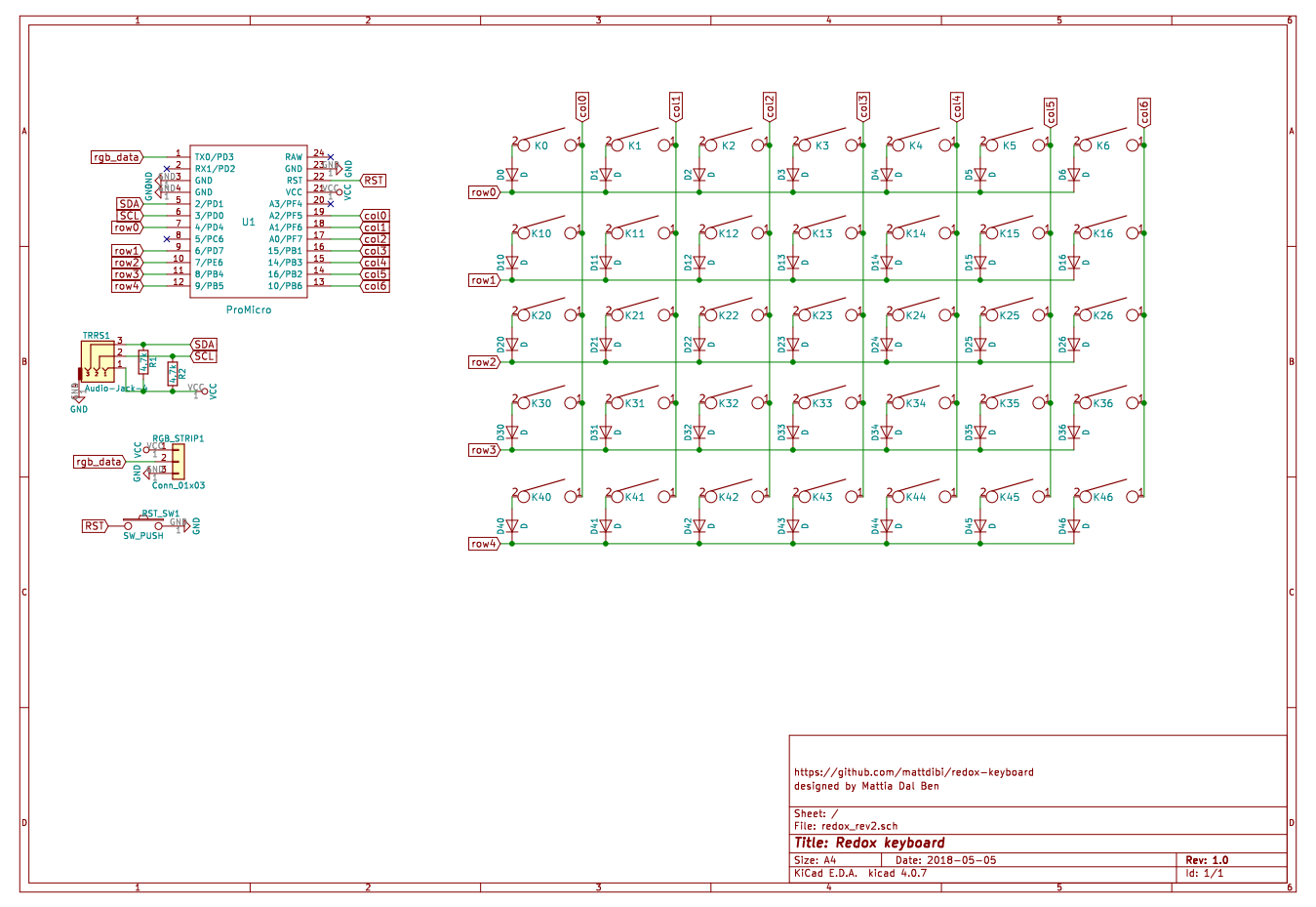
I used KiCad and this awesome guide to get things started. Since I didn't know if I could trust my skills and footprints I designed and manufactured a test PCB.
![]()
![]()
![]()
Needless to say it all worked out perfectly. I then extended what I already built and created the rev.1 PCB.
![]()
![]()
![]()
Then it was time for the hard part of the project: case design. My first idea went really bad: i wanted to replicate the handwired design but I couldn't get the angles just right and it looked horrible.
Also you may notice that my 3D printer had some problems in the final layers of the print.
![]()
![]()
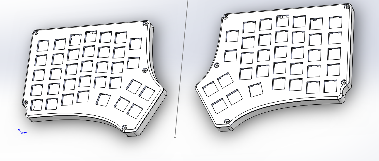
I then decided to change the design of the case and adopt curved lines all over the place. This was the design I adopted in the final version.
![]()
![]()
At this point I realized I needed a way to recycle my failed prints...
![]()
Final assembly.
Instructions can be found here. Case files are available on thingiverse.
Materials:
- 70x: Cherry MX compatible switches
- 2x: Redox PCBs
- 2x: Redox cases
- 70x: 1N4148 diodes
- 2x: PJ-320A 4 poles 3.5mm TRRS connectors
- 2x: 4.7kOhm resistors
- 2x: Through hole momentary switch
- 2x: Arduino pro micro
- 1x: TRRS cable
- 1x: USB micro cable
- 70x: Cherry MX compatible keycaps
- 10x (8x for 1u Layout): 1.25u keycaps
- 6x: 1.5u keycaps
- 54x (56x for 1u Layout): 1u keycaps
- 14x WS2812/WS2812B leds
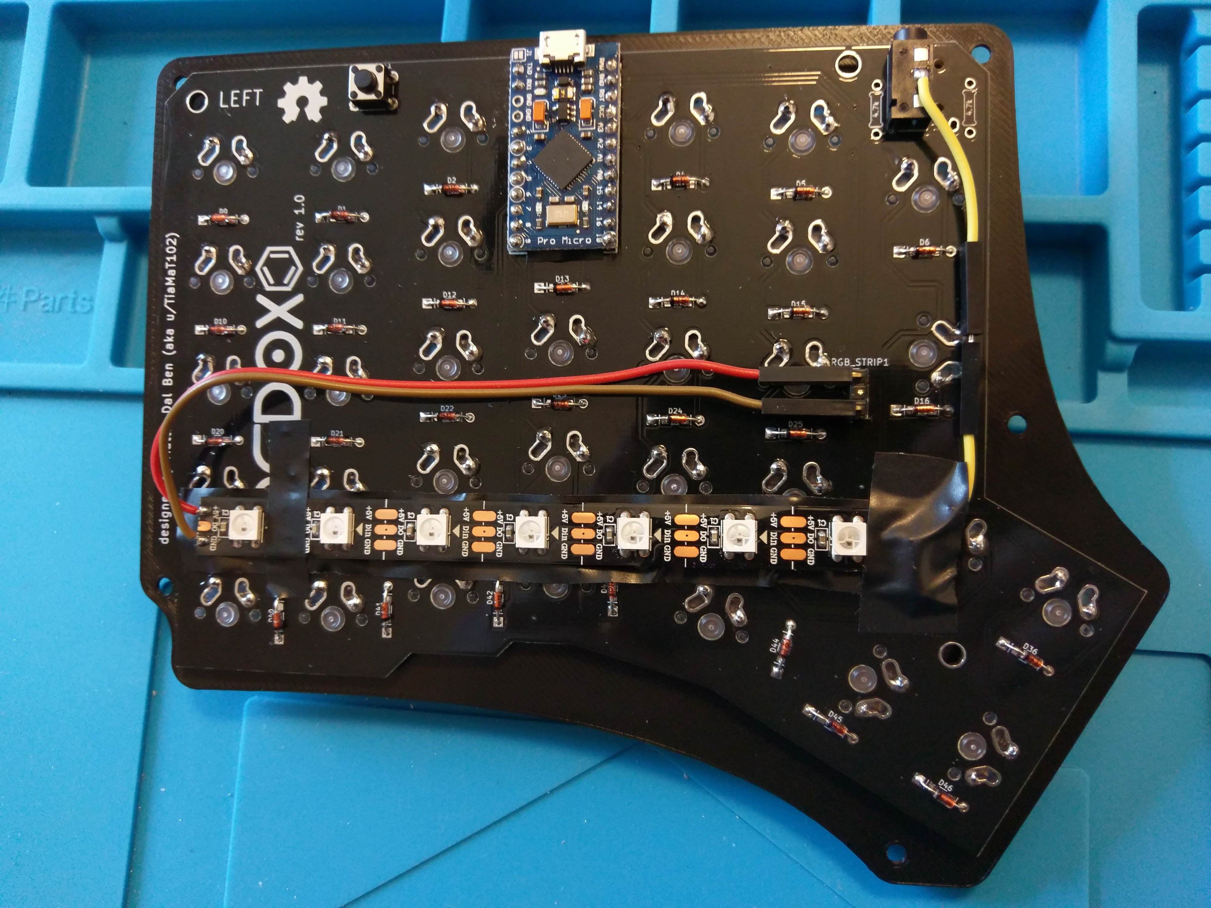
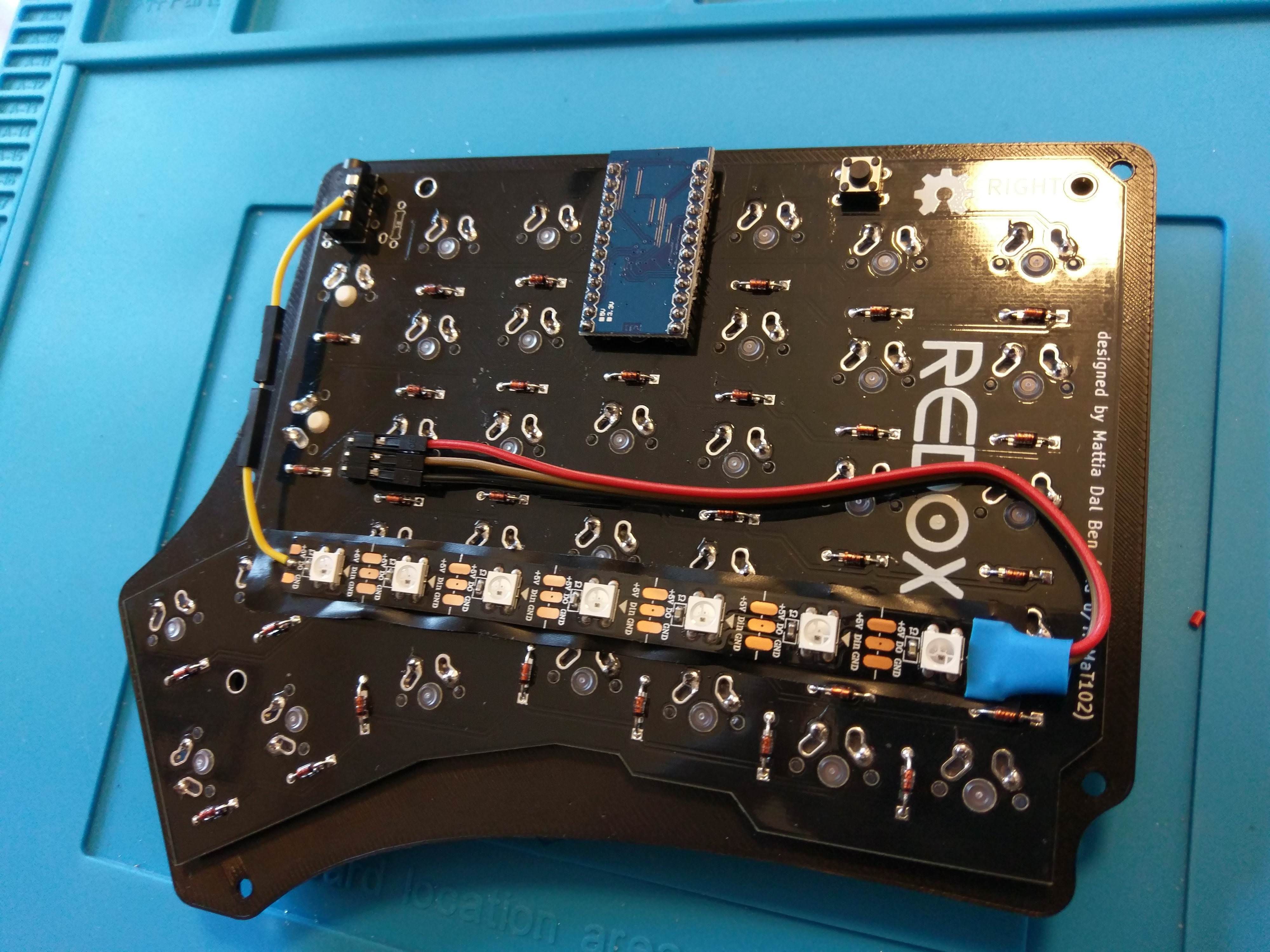
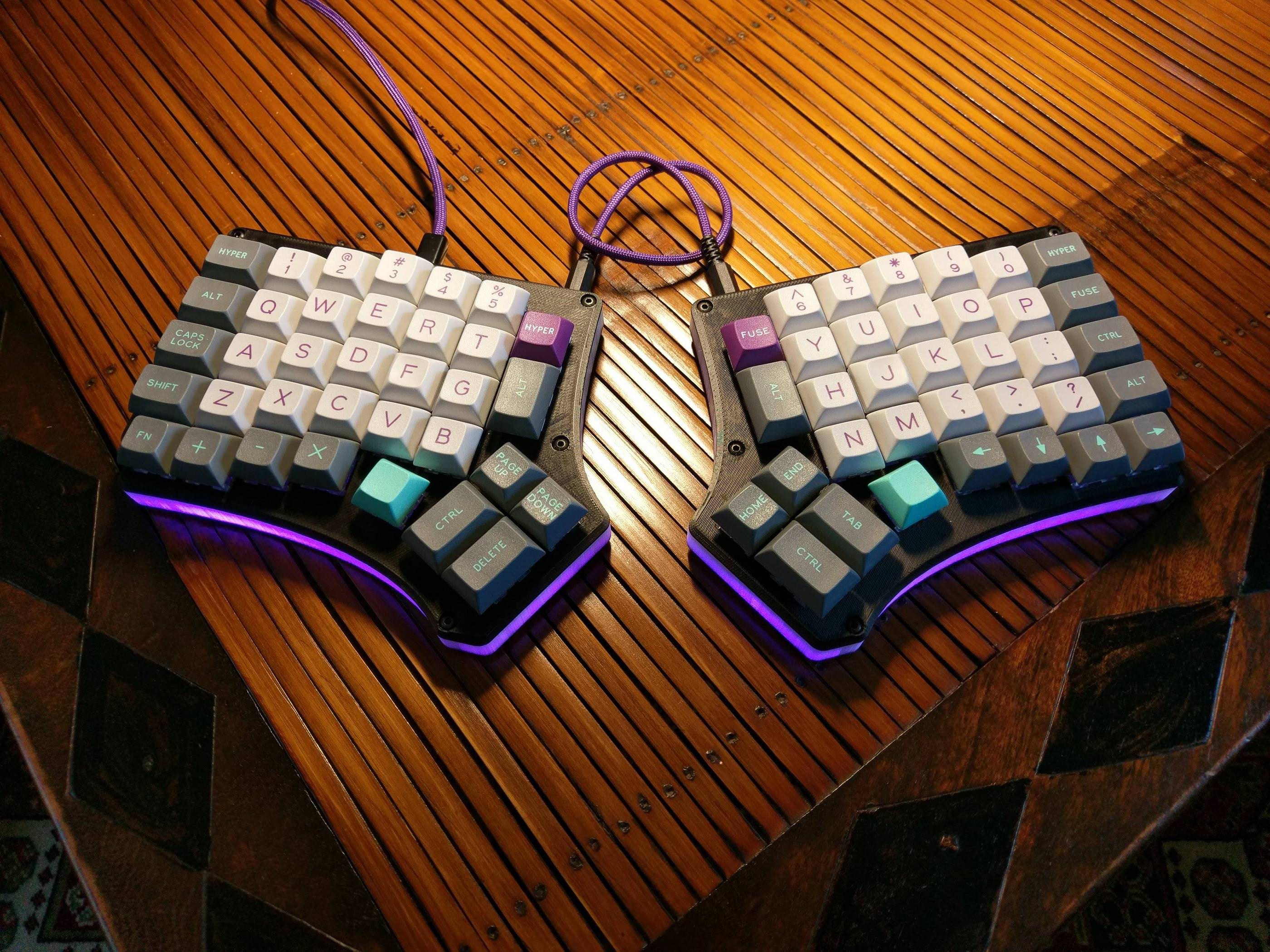
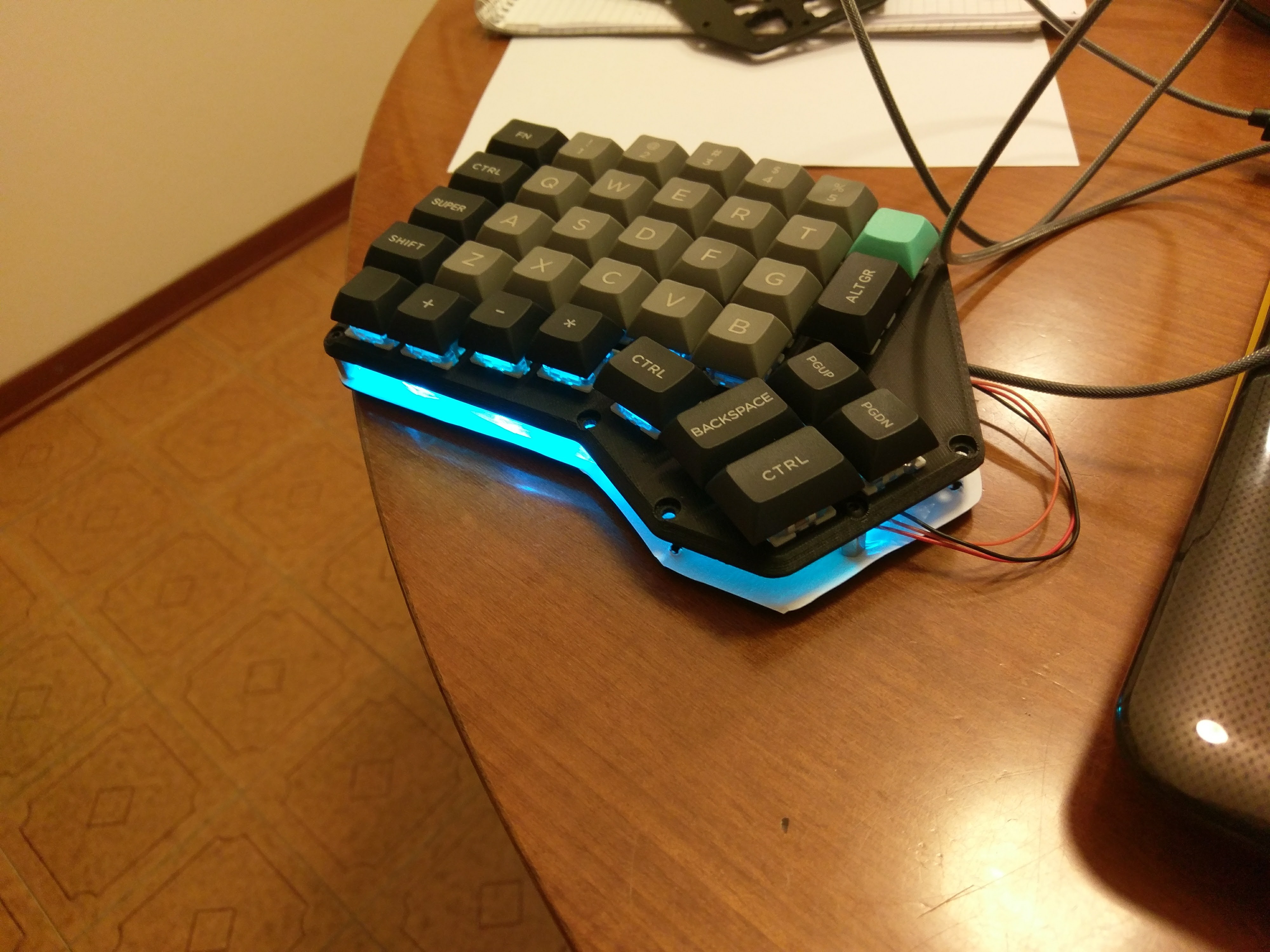
This time around I added LED backlight because I felt so.
![]()
![]()
At this point I should probably mention that I like purple...
![]()
![]()
After publishing some pictures of the PCB on instagram I was contacted by Falbatech and now the Redox is a product available on his store.
Redox rev1.0:
- 3D printed case, freely available.
- Rev1.0 PCBs: available at Falbatech's store
- Commercially available cases:
-
Redox handwire
08/20/2018 at 18:55 • 0 commentsThis was the first prototype for the Redox project. At the time I wanted only to test the ergonomics of the idea so I opted for a handwire.
Materials used:
- 70x: Cherry switches
- 70x: Diodes (I used 1N4148)
- 70x: Cherry compatible keycaps
- 10x (8x for 1u Layout): 1.25u keycaps
- 6x: 1.5u keycaps
- 54x (56x for 1u Layout): 1u keycaps
- 14x: M3 8mm screws
- 2x: 4 poles 3.5 mm panel mount plugs
- 2x: Arduino pro micros (Atmega32u4)
- 2x: USB micro male to female cable/adapter
- 2x: 3D printed cases
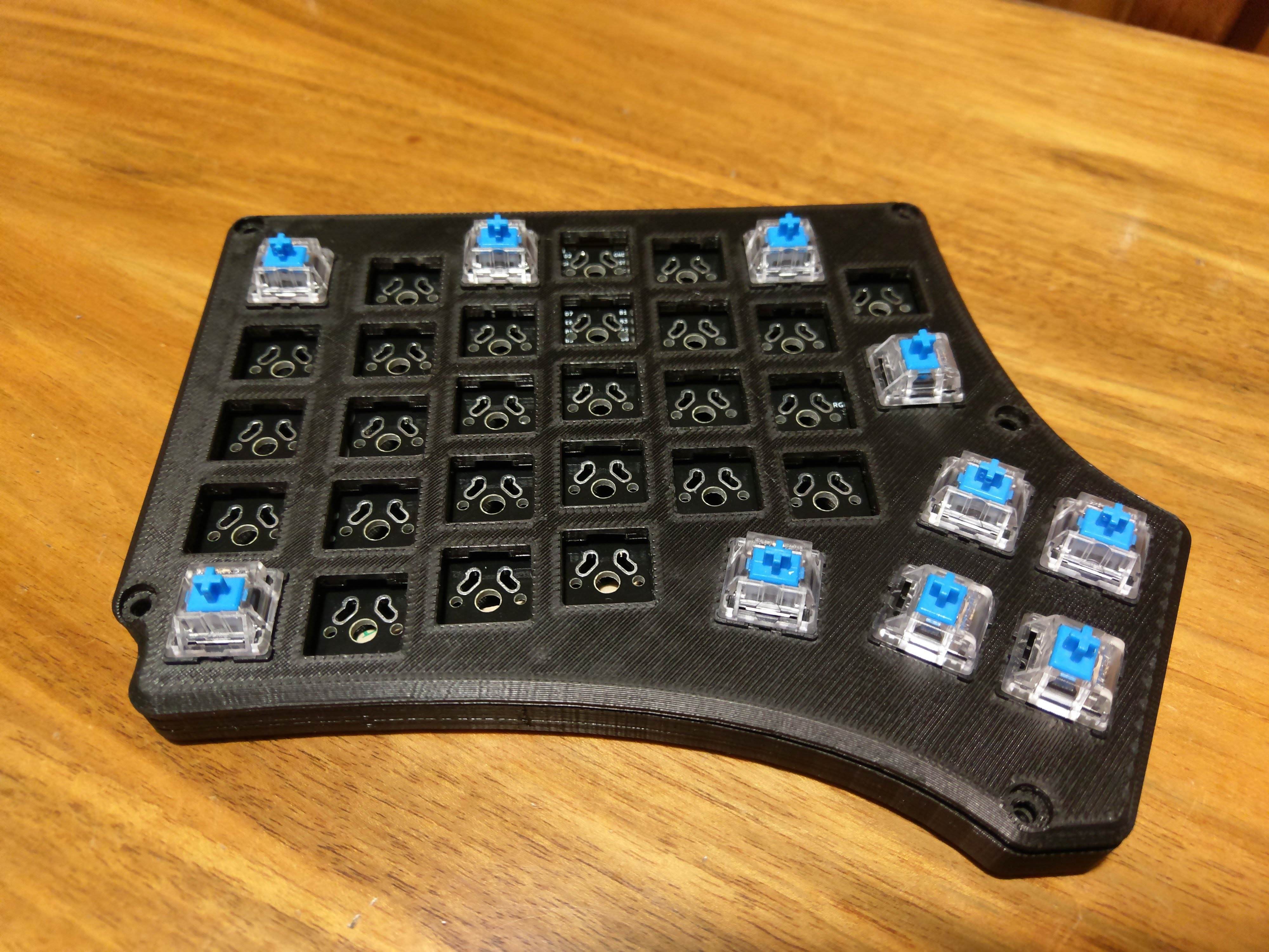
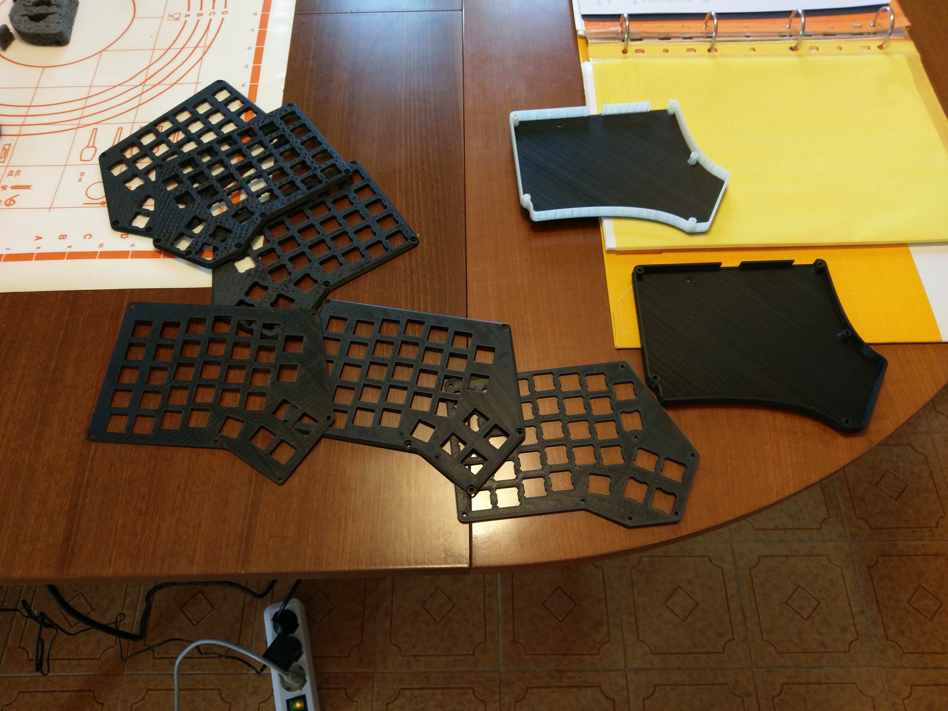
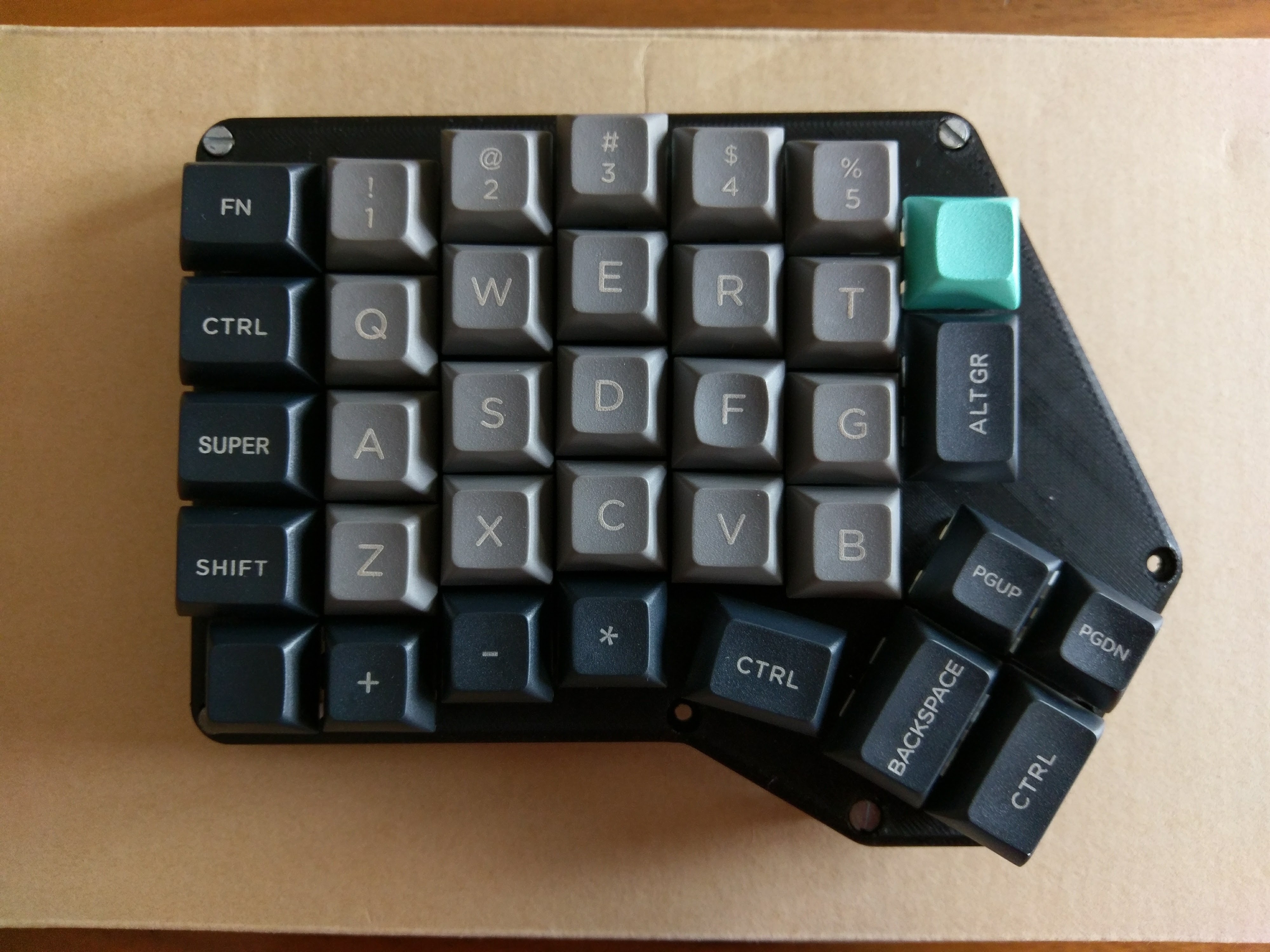
I started with the plate design. I 3D printed it and built my first mock-up. This was just for testing tolerances and checking that everything was fine (and cool looking).
![]()
![]()
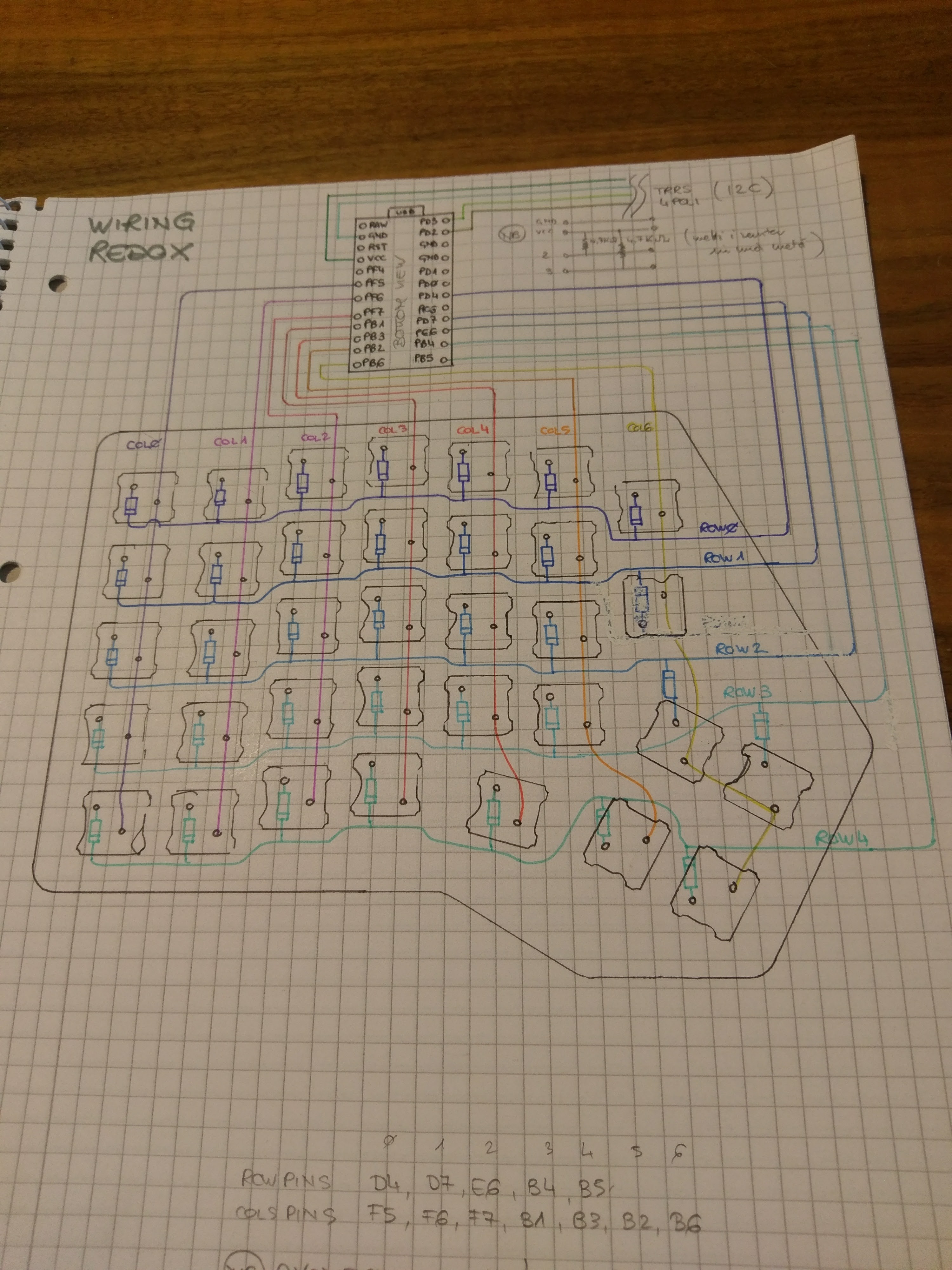
Then it was time to some proper planning for the handwiring. I started with a schematic then moved with the wiring planning on paper (it was easier this way).
![]()
![]()
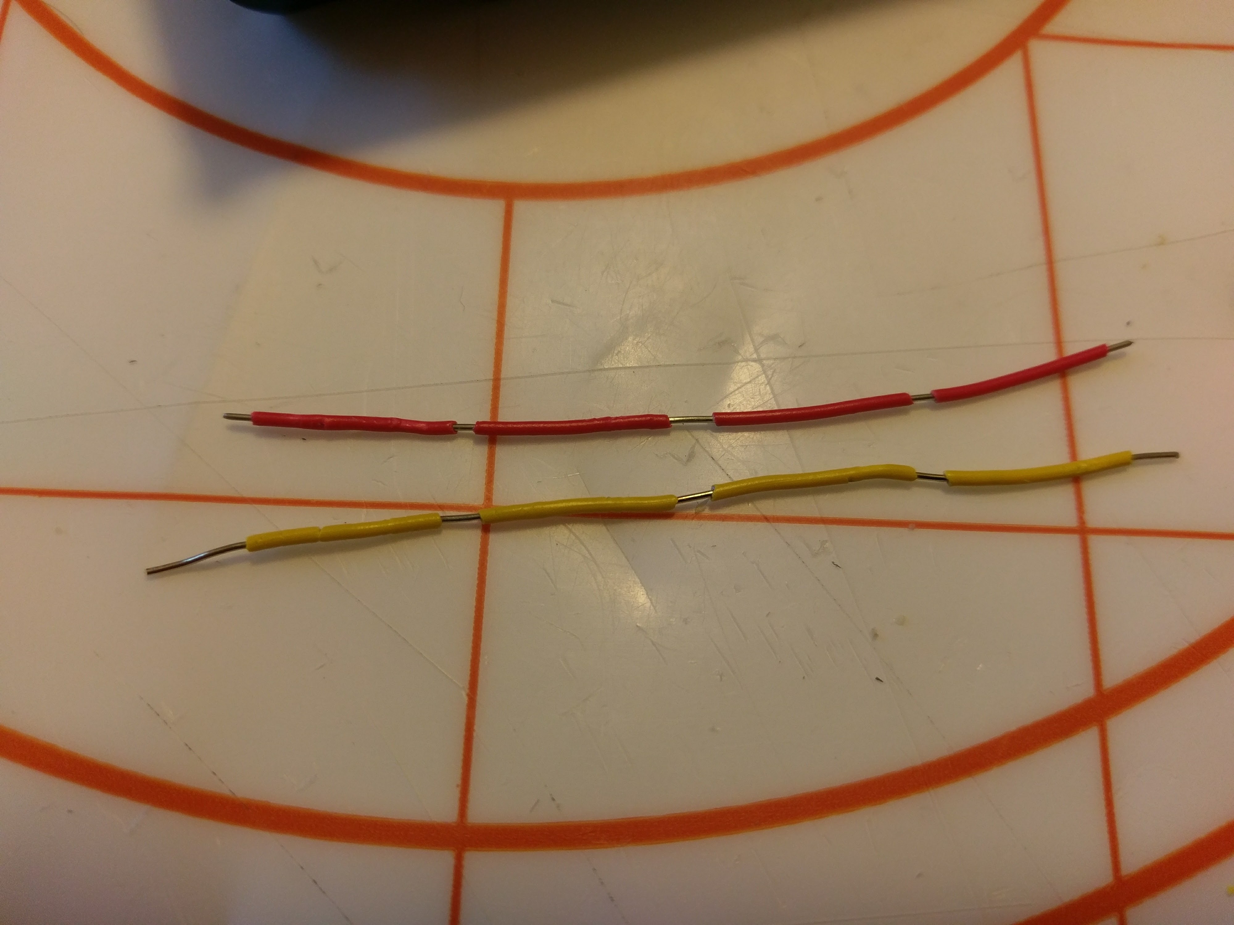
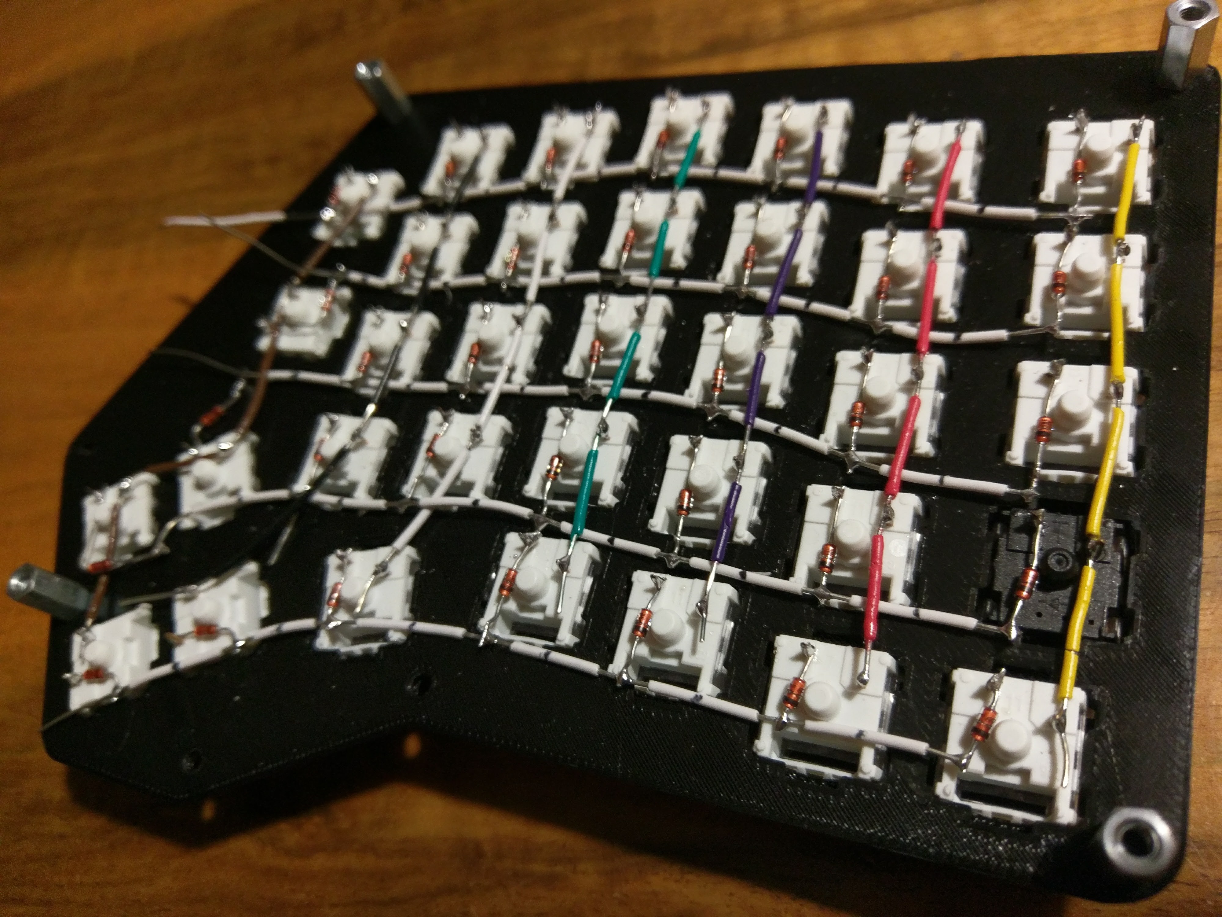
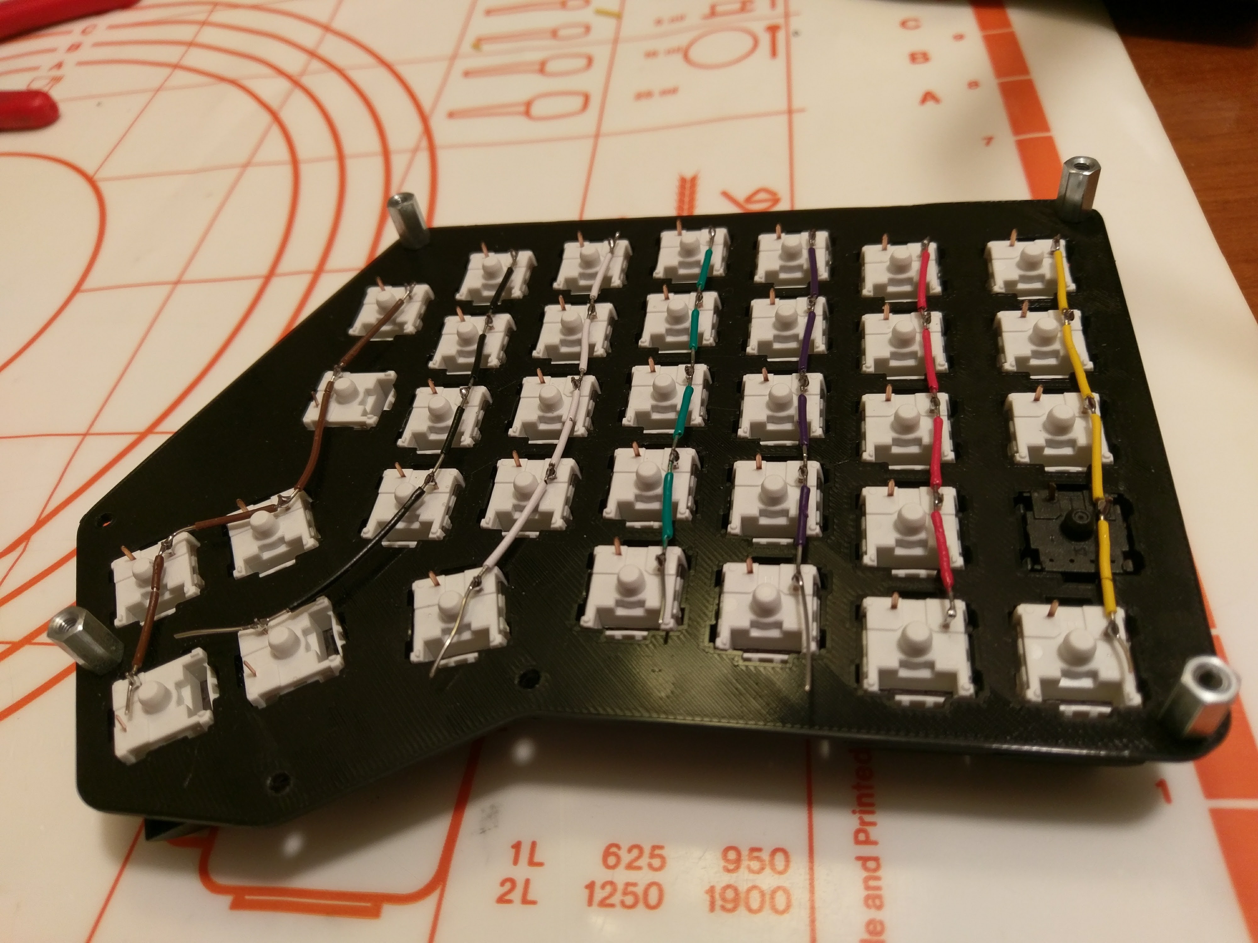
Finally I started soldering. My technique involves stripping the single-core wires so that the inner core is exposed at the height of the switch pin. Then I use the rigidity of the wire to make it stick to the pins alterinating the side which makes contact with the pin.
![]()
![]()
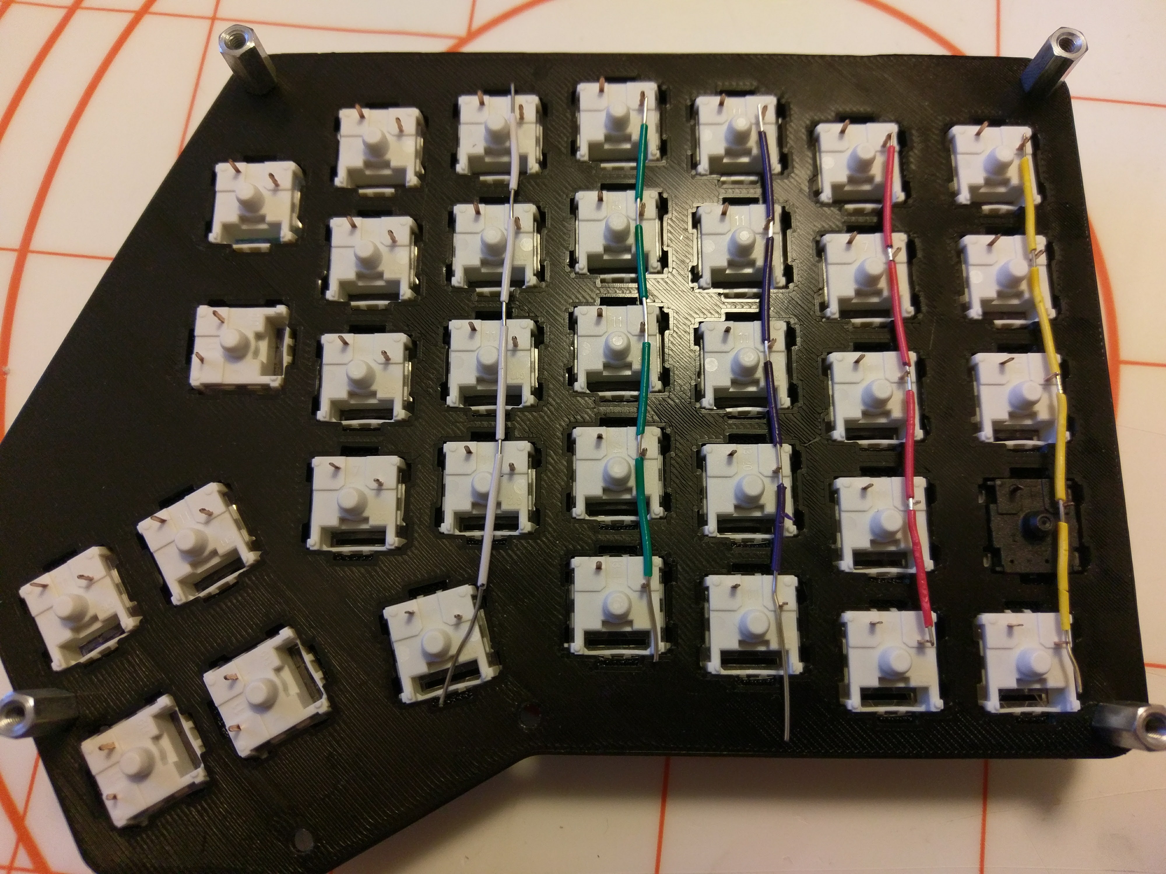
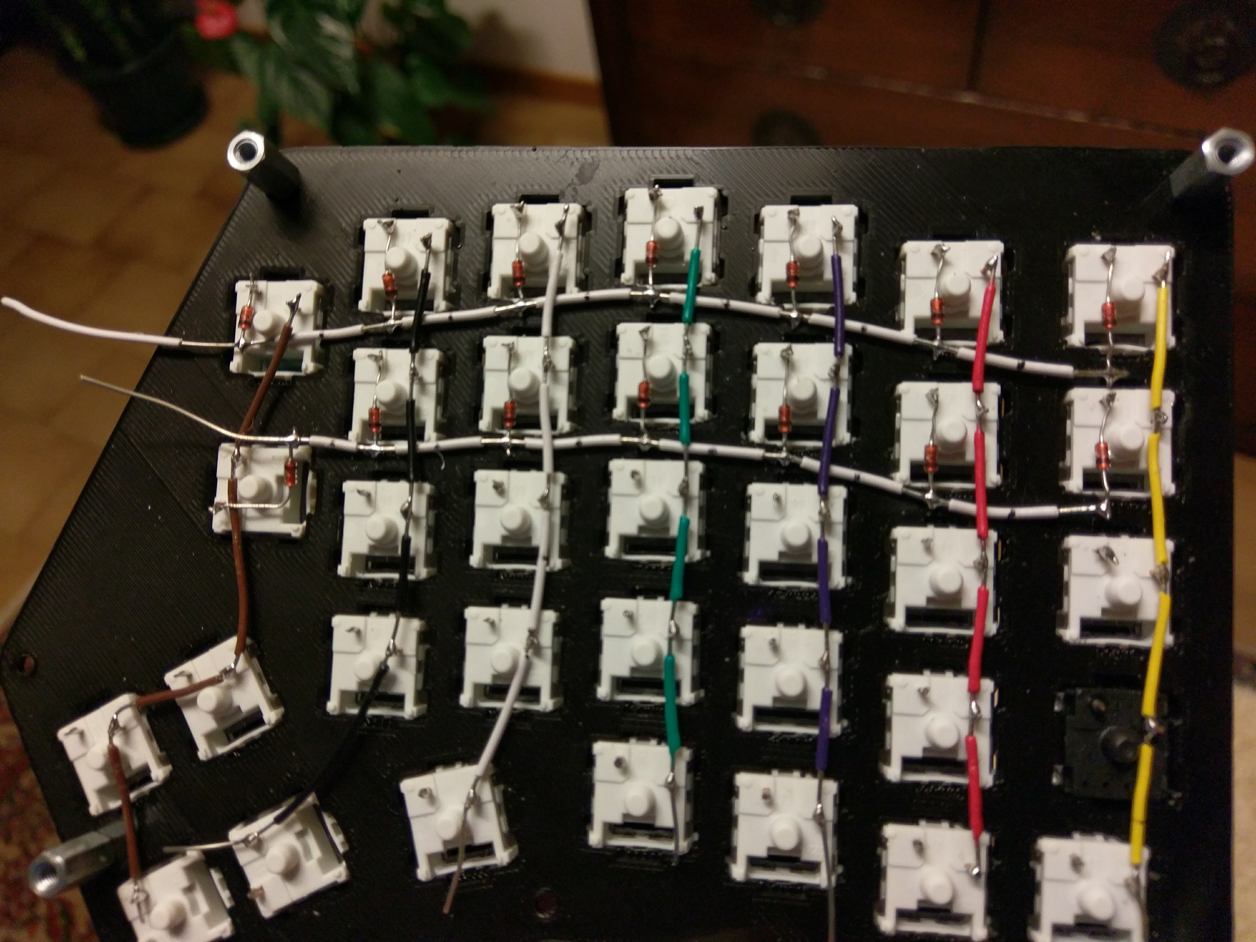
The it was a simple matter of patience and time...
![]()
![]()
![]()
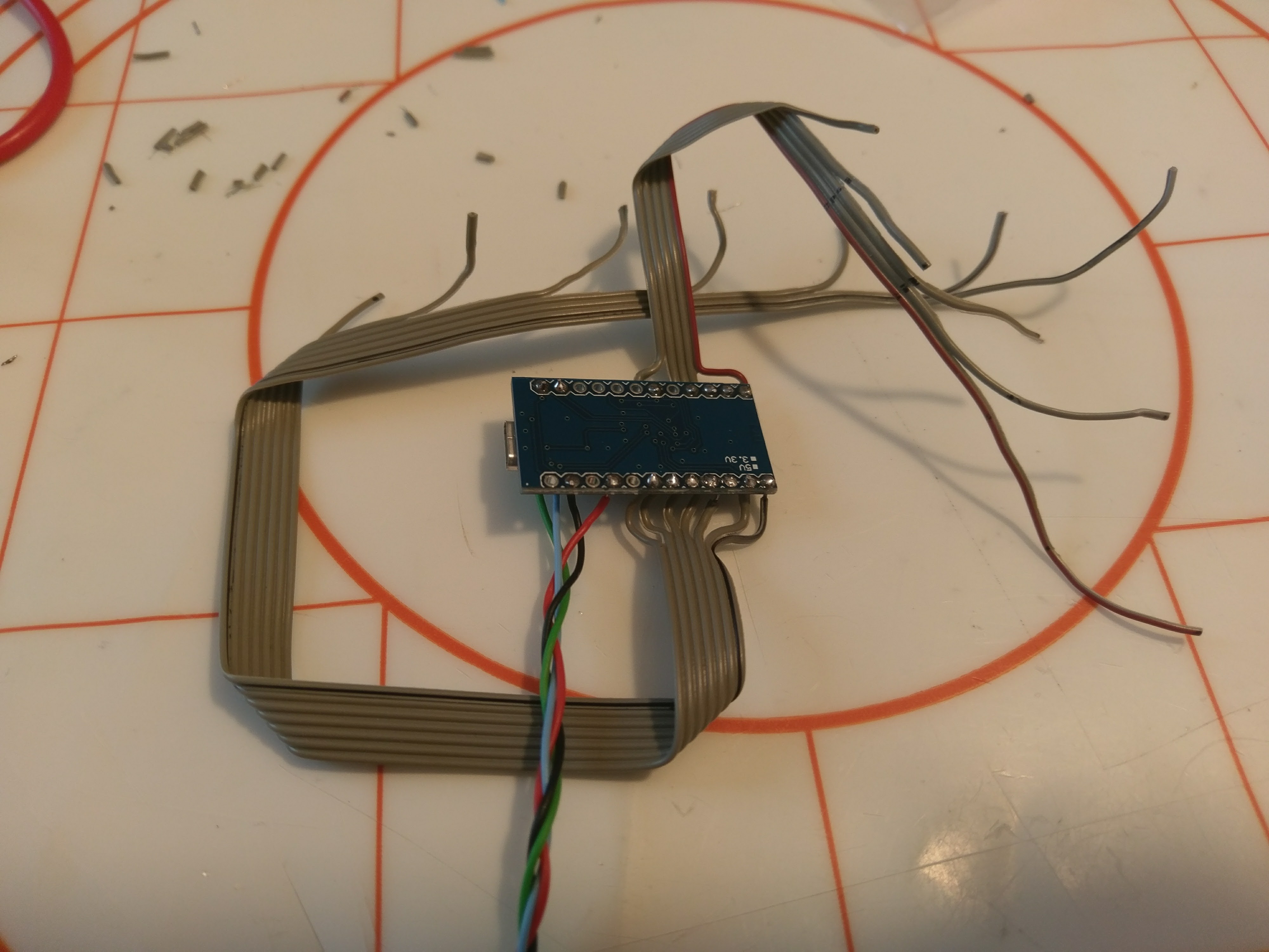
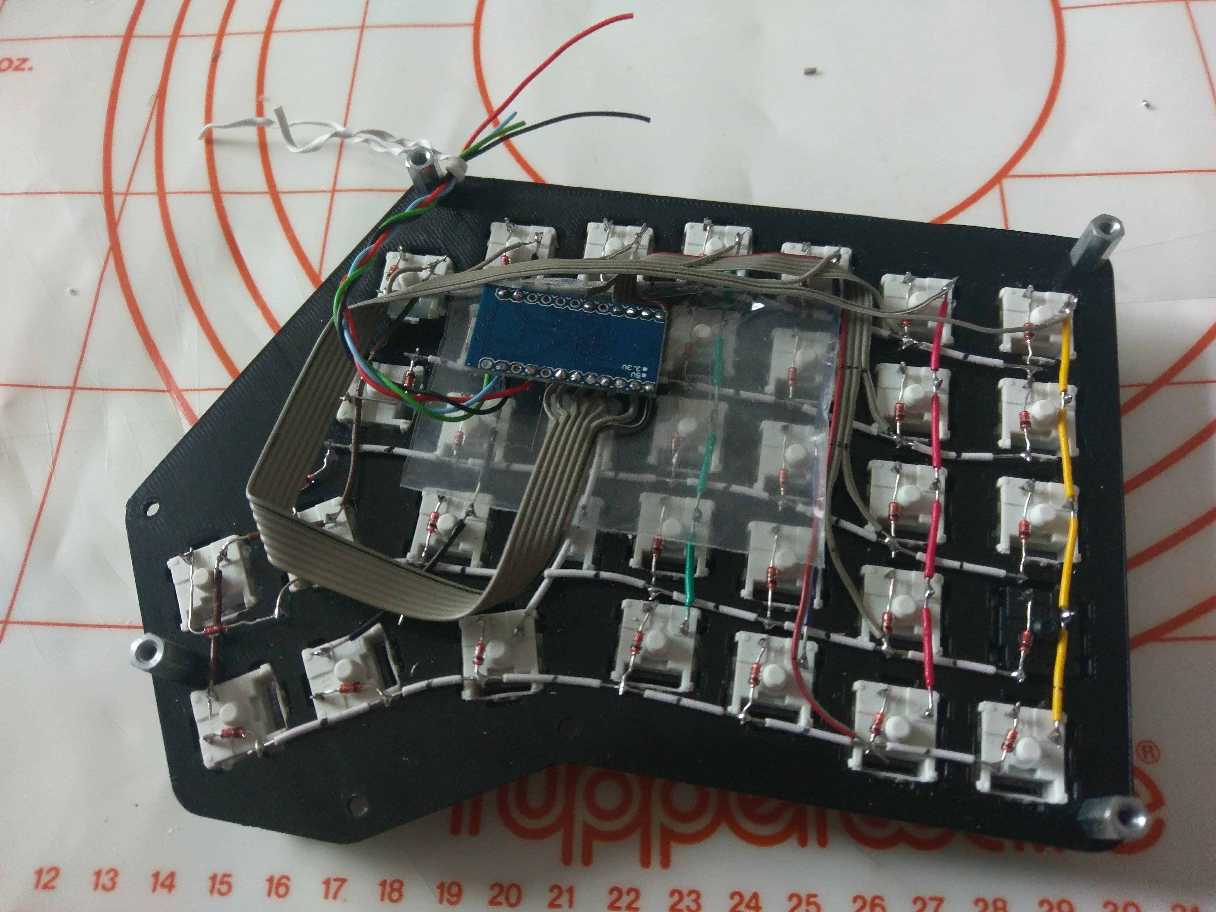
For wiring the controller I used some old IDE cables I had laying around. This helped a lot in cleaning the overall wiring mess.
![]()
![]()
Programming time. I based my keymap off of the Viterbi keyboard since it has the same number of keys. This way I sped up the testing phase.
![]()
I then added some LED backlighting for good measure because why not.
![]()
![]()
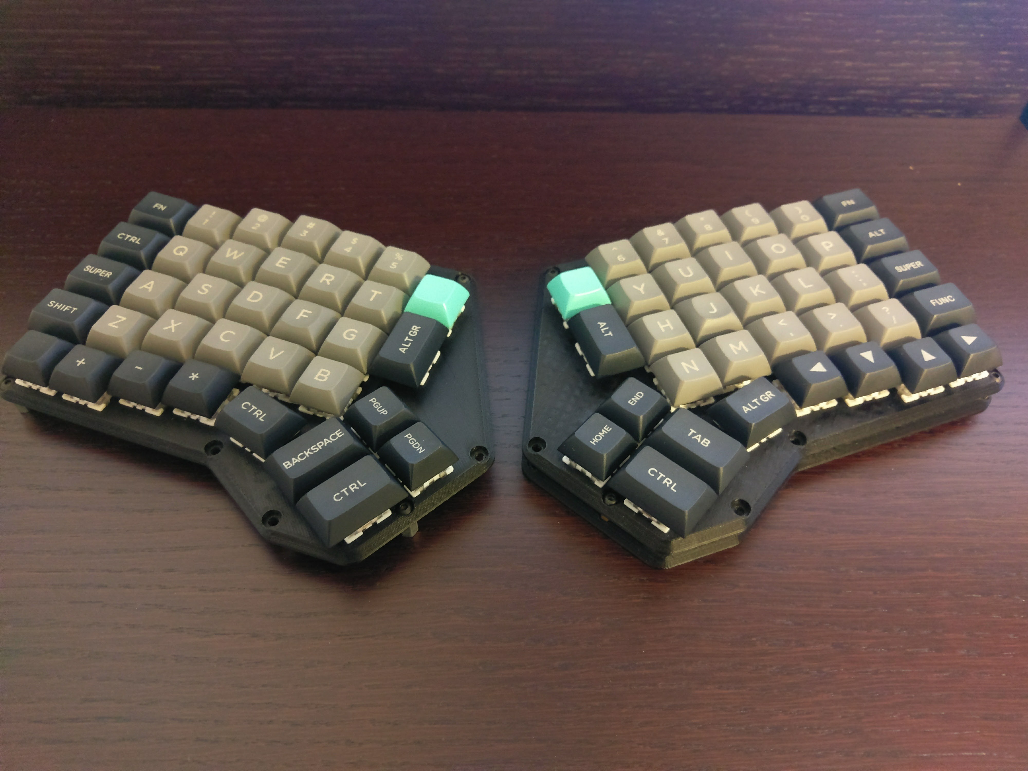
Finally I printed the bottom half of the case and finished the prototype.
![]()
![]()
Since its publishing the Redox handwire gained a lot of attention and inspired some great designs:
- Tilted Redox case: tilted case for the Redox prototype by jschloer.
- couscous-kbd: Redox-inspired parametric OpenSCAD keyboard design.
- Redox tenting kit: modified base to support tenting, mini-USB for the interconnect, and a hole for microswitch for reset needed when uploading new firmware by Lenbok.
- Iris-inspired Redox case: a case inspired both by the Redox rev1.0 and the Iris designed with OpenSCAD by Lenbok.
Redox keyboard
The Redox project is an open-source, QMK (Quantum Mechanical Keyboard Firmware) powered, ergonomic split mechanical keyboard.


 I am now waiting for the jumper cable to arrive to finally get writing some code. Once I get everything to work I'll begin designing the new PCB... my main goal is to make them compatible with the existing cases but I think this will not be an easy task.