Close
0%
0%

qlbrd (cool board)

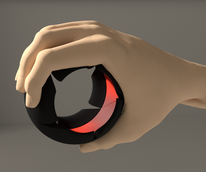
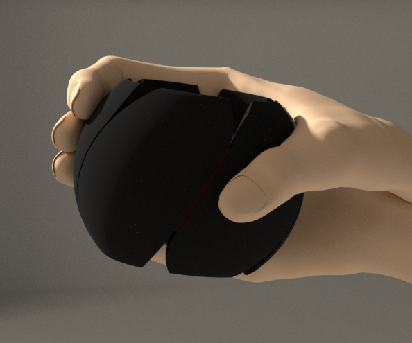
QLBRD is a ball shaped input device that attempts to solve issues related to ergonomy, usability and comfort of use of remote controllers.

dhgdhg
Similar projects worth following
QLBRD is a project of remote input device that is meant to be modular, versatile, health and user friendly. It consists of a ring with detachable modules that can contain a variety of electronic components, from microswitch based buttons through batteries, sensors, displays to microcontrollers. All communicate and share power via a common line built into the ring.
It can be worn like a bracelet. Thanks to customizable modules it can act as an input device, smart watch, simple phone and more.

QLBRD is a project aimed at solving certain issues I observed while using different models of remote controllers. Instead of listing what is wrong with them, it's more reasonable to say how my solution helps people interact with their devices.

MATERIAL FEEDBACK
QLBRD shape fits into human palm. It fills it. User can feel something under fingers, feels response of keys when they surrender to pressure. At the same time most of hand can remain relaxed without need to keep it in the air.

DIFFERENT POSITIONS
QLBRD can work in any position, user just holds it like a tennis ball and works by pressing keys and changes modes of operation by changing ball orientation in space. User can use it not only as a keyboard but also as a mouse like pointing device, 3d manipulator, game controller.

VERSATILITY
Thanks to Bluetooth interface QLBRD can interact with any device it can connect. There is a possibility to use different keyboard and controller profiles.

HEALTH
QLBRD can prevent carpal tunnel syndrome and similar conditions. CTS affects people working with computers whose work requires constant repetition of the same movements especially with excessive flexion and straightening of wrists.
Using QLBRD can bring relief in suffering from such conditions as it forces movement and training of wrists while it does not require constant strain in muscles.

MODULARITY
QLBRD is meant to be composed of different modules sharing common data bus and power line. Modules are attached to main ring and are swappable. This enables for easy extension and adaptation to different tasks.

PORTABILITY
QLBRD can be worn on hand like a smart bracelet. More, in such position and with added modules it may be used as a smartwatch (with addition of eink module and possibly a gsm one as well).

SIMPLICITY
My aim is to have a device that can be assembled using off-the-shelf components and some skill. 3d printer can be of help when it comes to plastic parts, but I provide all project files that can be ordered with external service providers as well.
It's worth mentioning that I do not deal with such maker activities on a regular basis and thus have limited lab equipment. If I am able to make it, everyone can.
nodes.blend

parametrized node setup

x-blender - 1.11 MB - 09/03/2018 at 20:15

Download

qlbrd-rough-presentation.blend

rough presentation of QLBRD made in Blender

x-blender - 6.89 MB - 08/26/2018 at 09:10

Download

license.txt

License with legal disclaimer

plain - 20.39 kB - 08/26/2018 at 09:09

Download

  • 1 × Adafruit Blufruit LE 32u4 + Bluetooth LE
  • 1 × LiPo cell 200mAh 3.7V
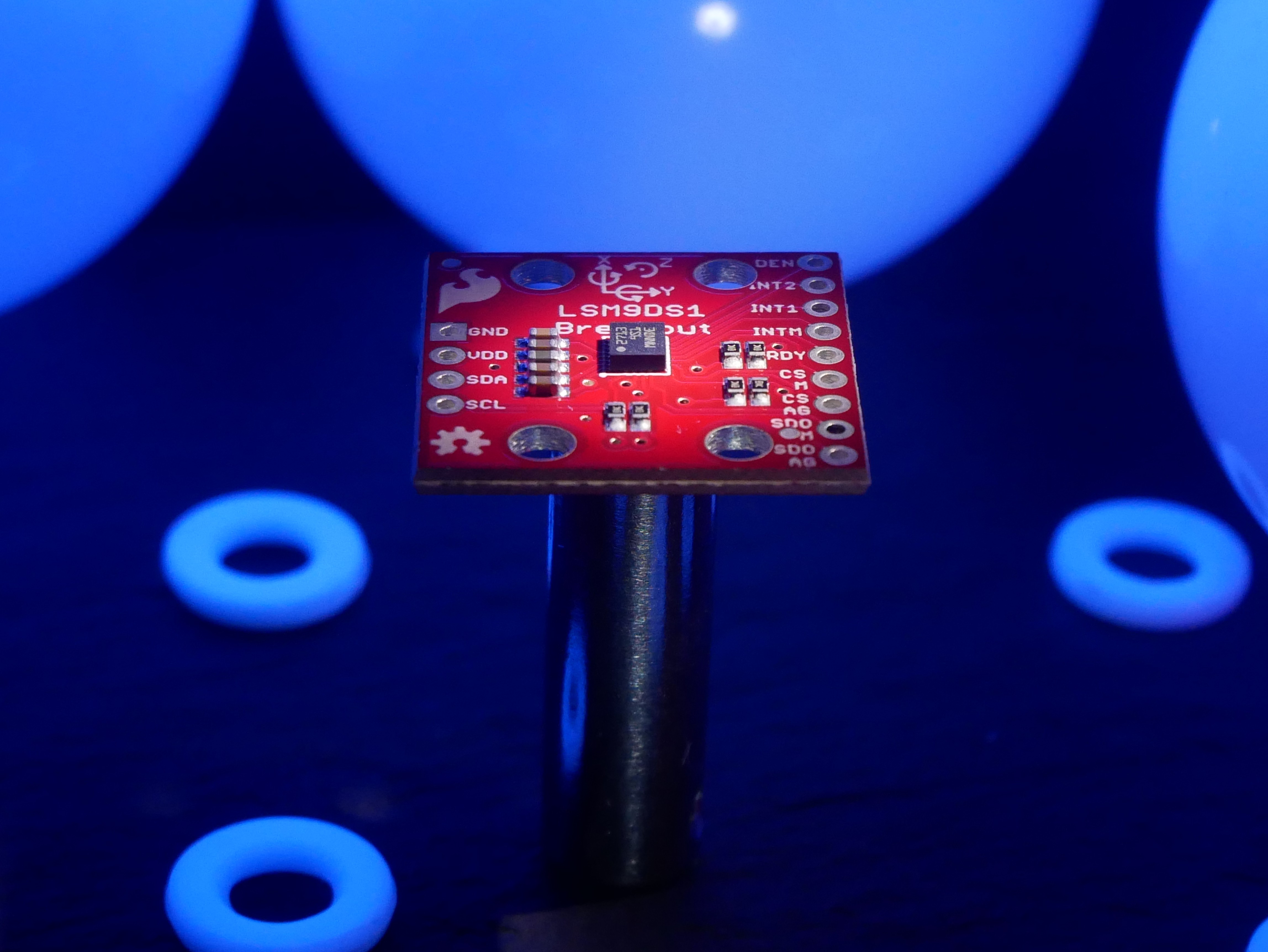
  • 1 × 9DoF LSM9DS1 accelerometer/gyro/magnetometer
  • 10 × microswitches smd as small as possible
  • 1 × 4 ways microswitch optional

  • Parametrization in action

    dhg09/03/2018 at 20:14 0 comments

    As promised I publish some parametrization setup in Blender (that uses great Sverchok addon) intended to provide an easy tool to make QLBRD clones. It has lots of settings that can be manipulated.

    It took me some time to publish it as the worst part of any code is documentation. But finally I found needed power to both write some explanation in code and make a small presentational render you see below (however was too lazy to add sound).

    A more detailed description will put in instructions. A file with node setup lands in project files.

  • Parametrization and website

    dhg08/28/2018 at 16:37 0 comments

    Today (and yesterday as well) I was focused on parametric modelling of QLBRD in Blender. I just like open solutions even if they give no ready solutions. There is an addon which I use a lot called Sverchok. It provides many tools to parametrize geometry. Soon will post the results.

    Meanwhile I wrote a simple website for my project, you can find it at http://qlbrd.com

  • Structure visualization

    dhg08/27/2018 at 06:12 0 comments

    Render visualizing internal QLBRD structure supplementing previous logs.

  • Components photos

    dhg08/26/2018 at 09:37 1 comment

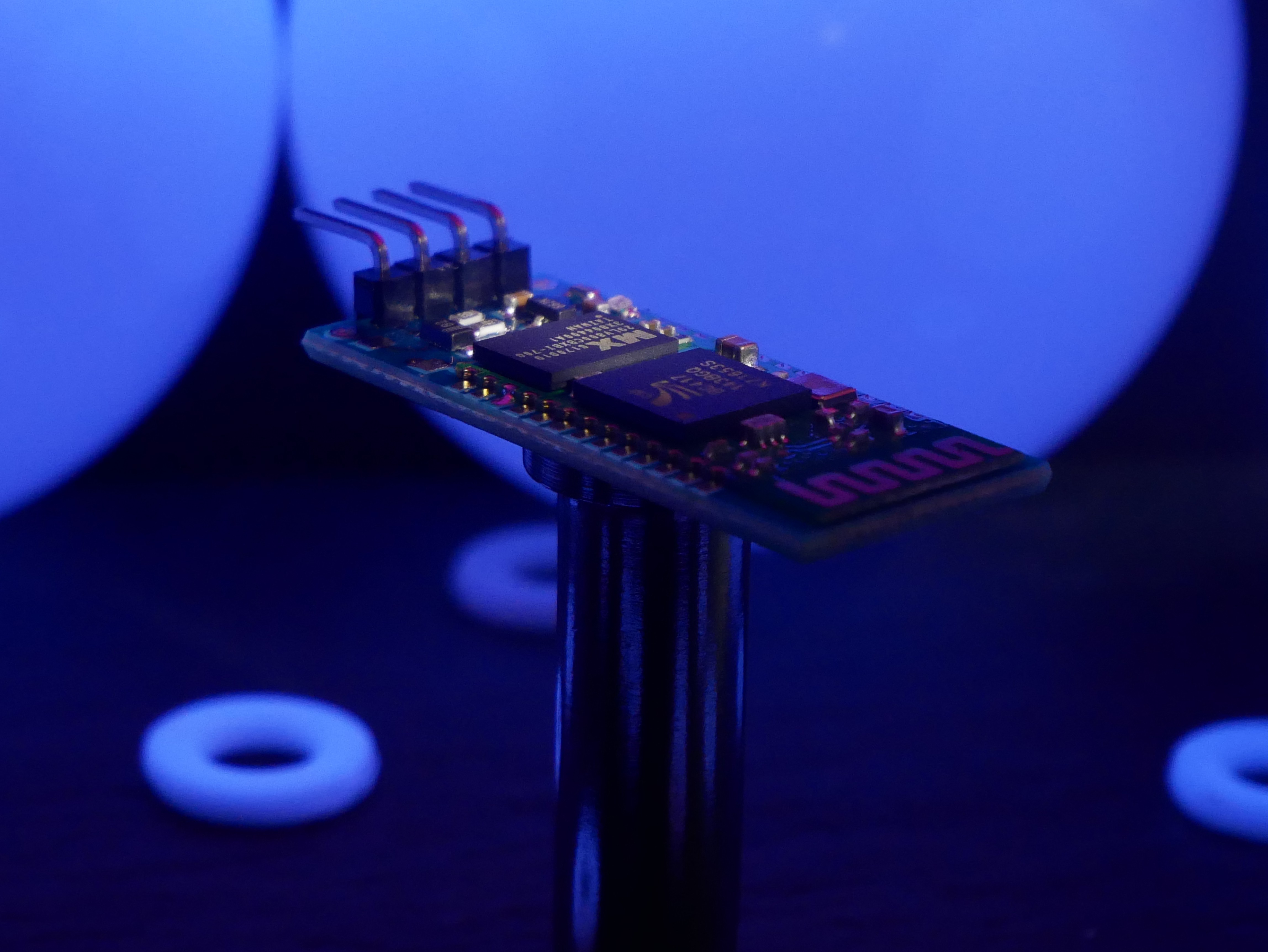
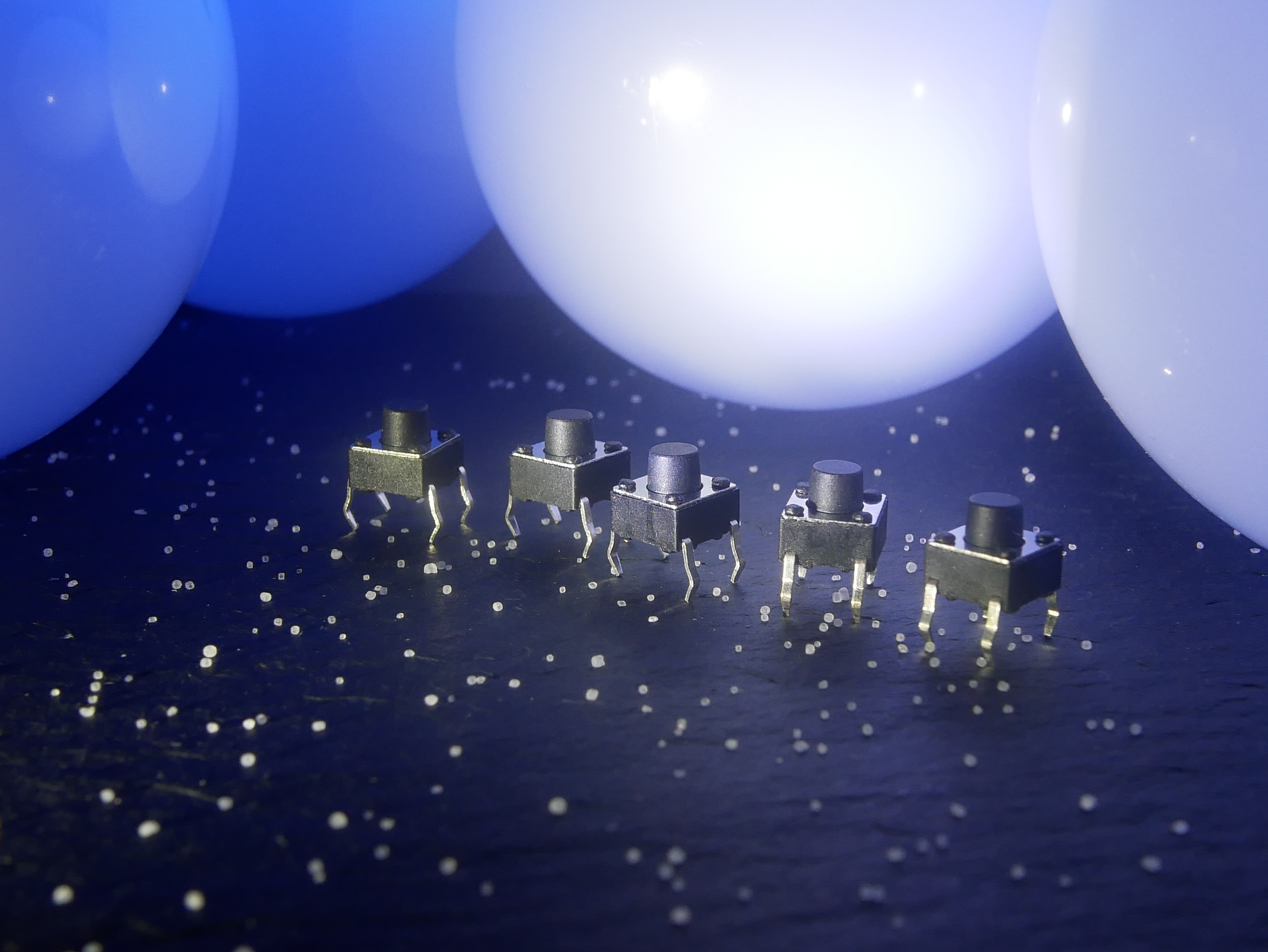
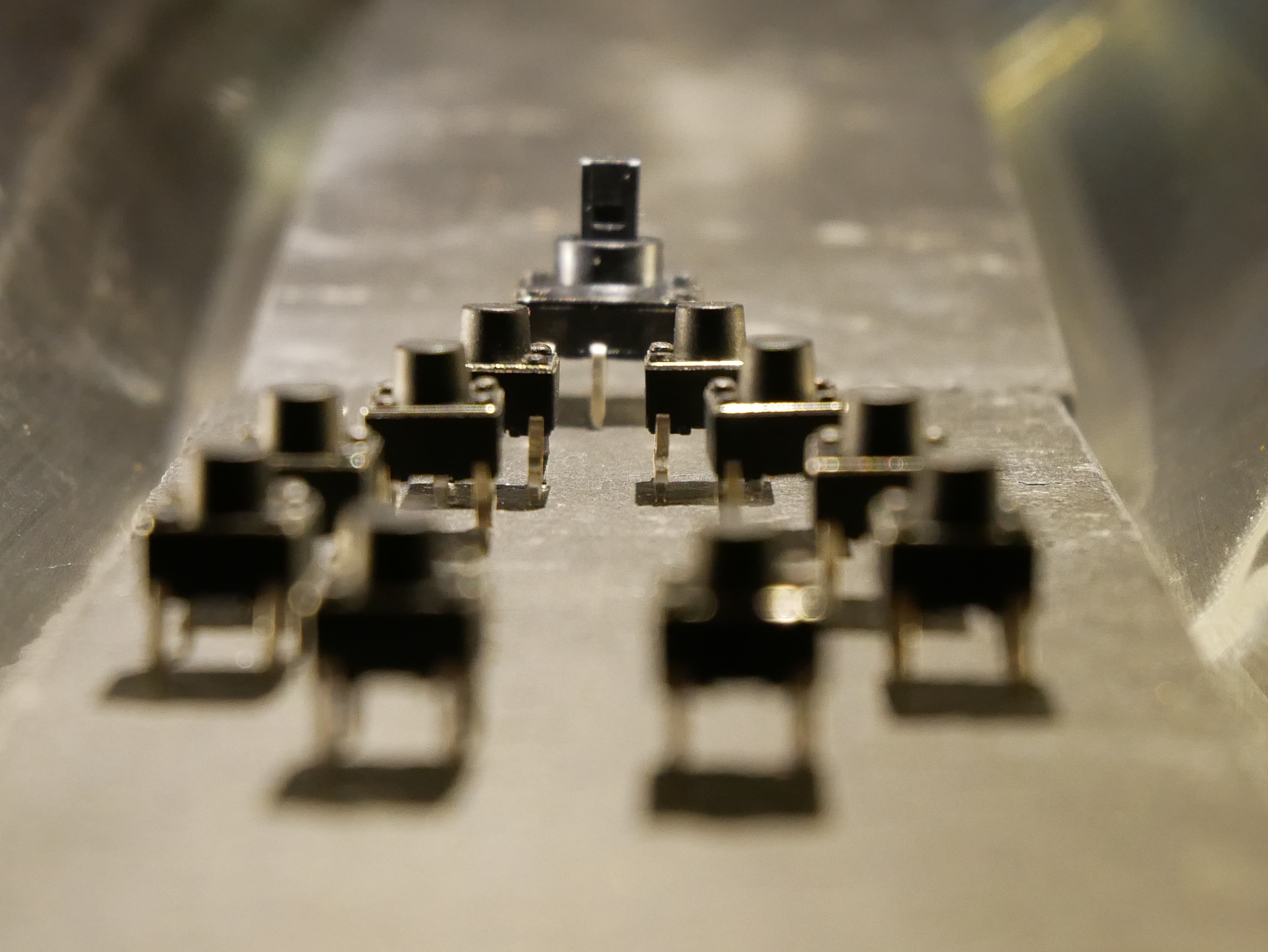
    As I like documenting what I make with artistic twist below are photos of components that we make together with @Freya (published with permission). I helped in making them very little :) .

    9DoF LSM9DS1

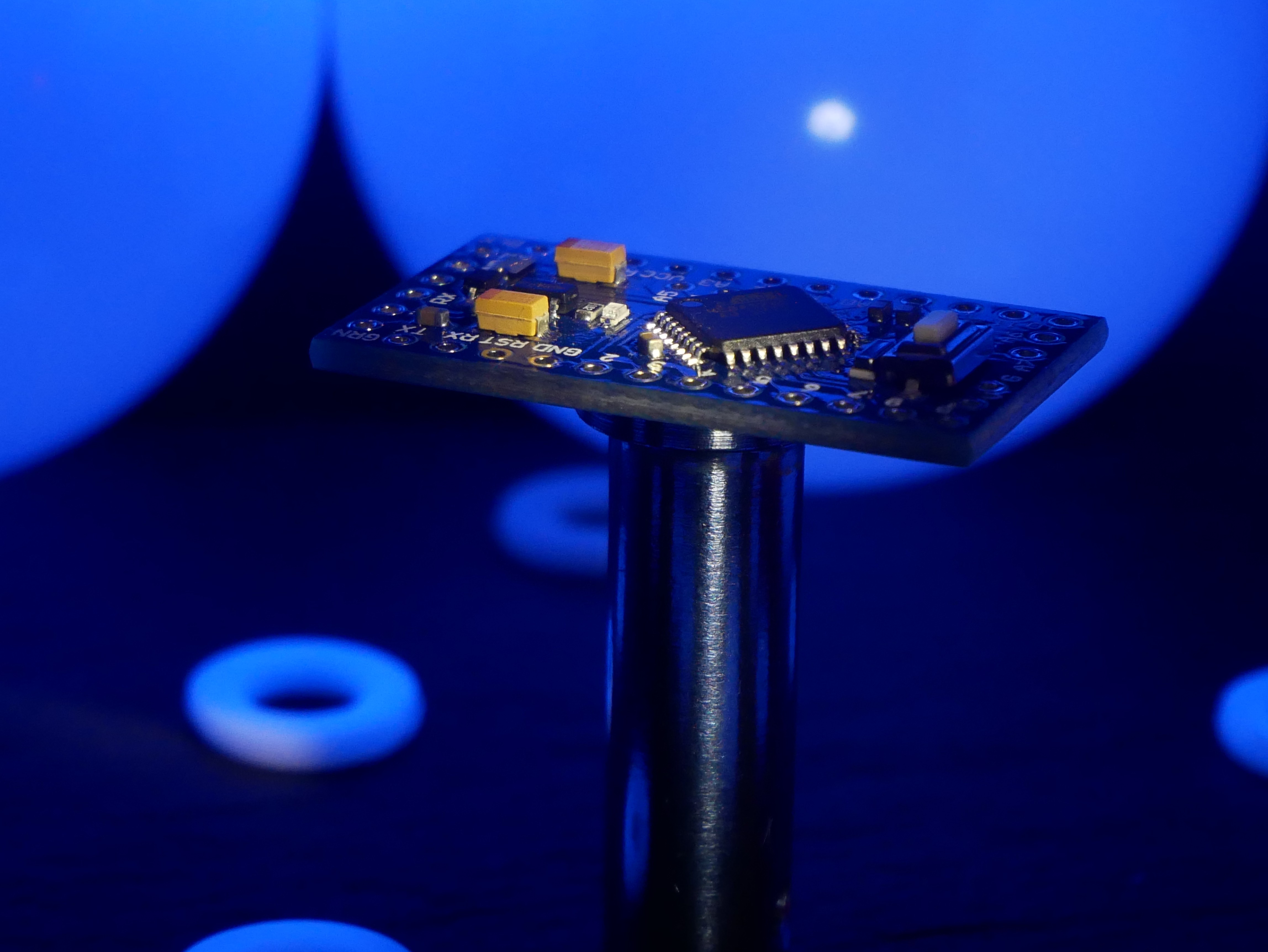
    Arduino 328 (won't be included in project, however initially I wanted to use it coupled with bluetooth module)

    said bluetooth module - can be of use anyway

    tiny storm troopers

    following their leader :) .

  • Electronic configuration

    dhg08/26/2018 at 09:25 0 comments

    The most basic setup of QLBRD will contain simple and popular among makers set of readily available modules - Adafruit Blufruit LE coupled with accelerometer (in my case 9DOF I mentioned already, so accelerometer/gyro/magnetometer). This setup will be fed with additional input from set of microswitches mentioned as well. Power will be provided by 200mAh single LiPo cell or set of five 40mAh cells placed in "wings". The second solution, while tempting can require a balancer for cells. Blufruit power consumption is around 13mA or so while active so batteries should last for long enough.

    Modular structure of QLBRD enables me to add more modules with time and will publish their description as they are developed.

  • Principle of operation

    dhg08/26/2018 at 09:24 0 comments

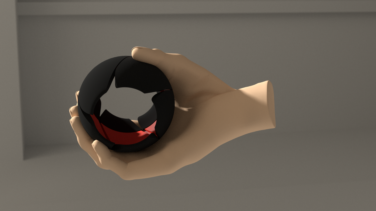
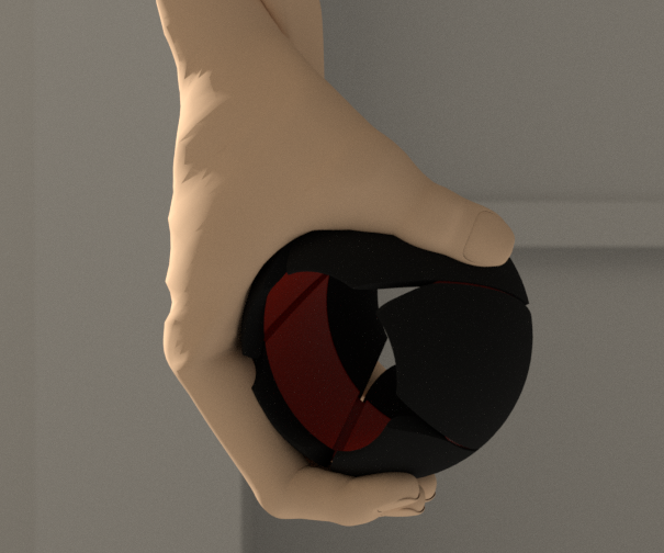
    QLBRD is a input device (however can be a smart watch or phone as well if appropriate modules are plugged). Basic operation is simple. At the moment I plan to use 8 switches acting as buttons operated by one hand fingers (2 for index finger, middle and thumb and one for ring and pinky). This number isn't a hard limit, as for instance thumb switches can be replaced by 4 ways micro switch (joystick). As QLBRD has 9DOF (defrees of freedom) accelerometer/gyro/magnetometer it can detect hand position with high precision. There will be up to five basic positions relative to current working plane (more on this later) - up, side, down, front-up and front-down (first three are most useful though). Initial base position can be horizontal, vertical or whatever between. But lets assume you sit on a sofa with your hand freely resting aside with ball in palm:

    So side position would be:

    And down position:

    Front-up and front-down are when delta of rotation in whatever configuration goes in clockwise or counterclockwise (in relation to sensor) but the plane of rotation is stable.

    Of course initial position can be whatever, as I mentioned. Vertical for instance:

    Which can occur for instance when you stand in front of high desk.

    Mapping combinations of positions and keys will give full character set (and even more, like macros, if multiple keys pressed at once). At the same time QLBRD can also serve as pointing device, 3d manipulator or game controller if switched to this mode.

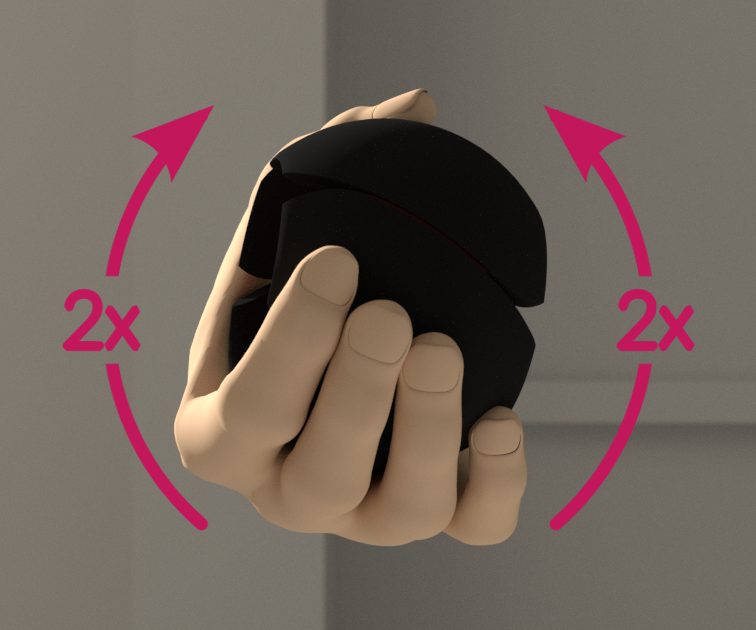
    As to the working plane - there is no hard set position with relation to body in which mentioned positions should work. Wobbling hand twice clockwise and counterclockwise will tell the device to set the working plane. So, user can rest on his back, stand seat, have hand in any position and still be able to use QLBRD.

    Wobbling like this:

    Note: I tried to adjust a rig little too fast, so the hand you see isn't perfect (delicately speaking). More, proportions are close, but not perfect as well. Hand rigged model by by UP3D taken from http://www.blendswap.com/blends/view/75824 .

  • QLBRD Structure

    dhg08/26/2018 at 09:01 1 comment

    Note: presentation renders are pretty accurate when it comes to dimensions, but some details are still missing.

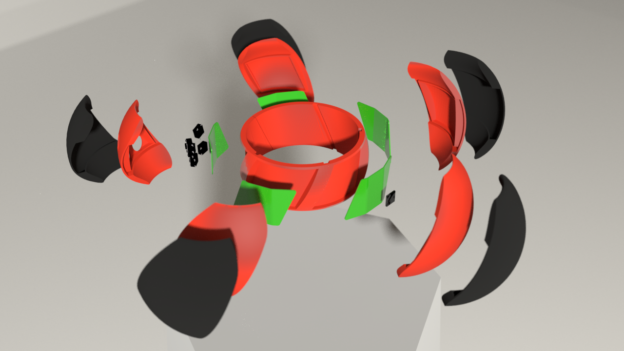
    In terms of mechanical structure QLBRD is composed of three layers, two of them are made of five identical segments:

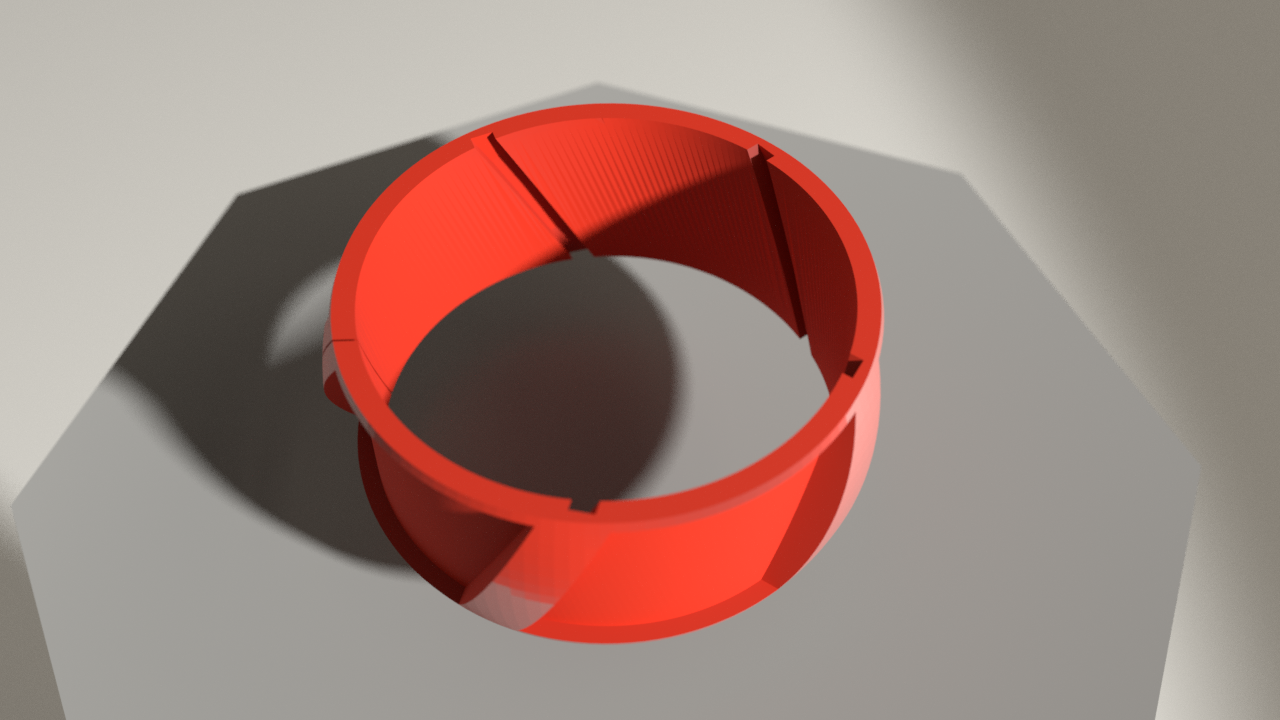
    The innermost part is frame ring already mentioned in previous log:

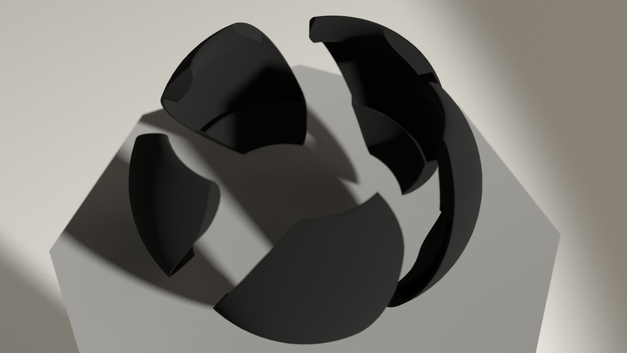
    The middle one is stiff (printed most likely out of PLA filament) set of five modules. They serve as skeletons for outermost layer:

    The outermost modules are wraps for ones from previous layer printed in flexible, rubber filament (most likely TPU). Modules (middle and outermost layers) will be printed as one piece with double or triple extruder. I will try both solutions as I recently finished my two extruders printer. Triple extruder can help when it comes to PVA (solvable filament) supports that would enhance precision.

    Modules are mounted to the frame ring (for now I prefer screw mounts, but will work on some latches). When mounted contacts of PCBs inside modules will meet contact fields of common power and data lines on the ring. I consider two ways of making these lines, first, easy and fast is to make them out of kapton metallized with copper with etched leads glued onto the ring. Second, that may require some experimenting is to use conductive filament and PLA to form leads directly into plastic. For sure will try this, but cannot yet tell how viable is this solution.

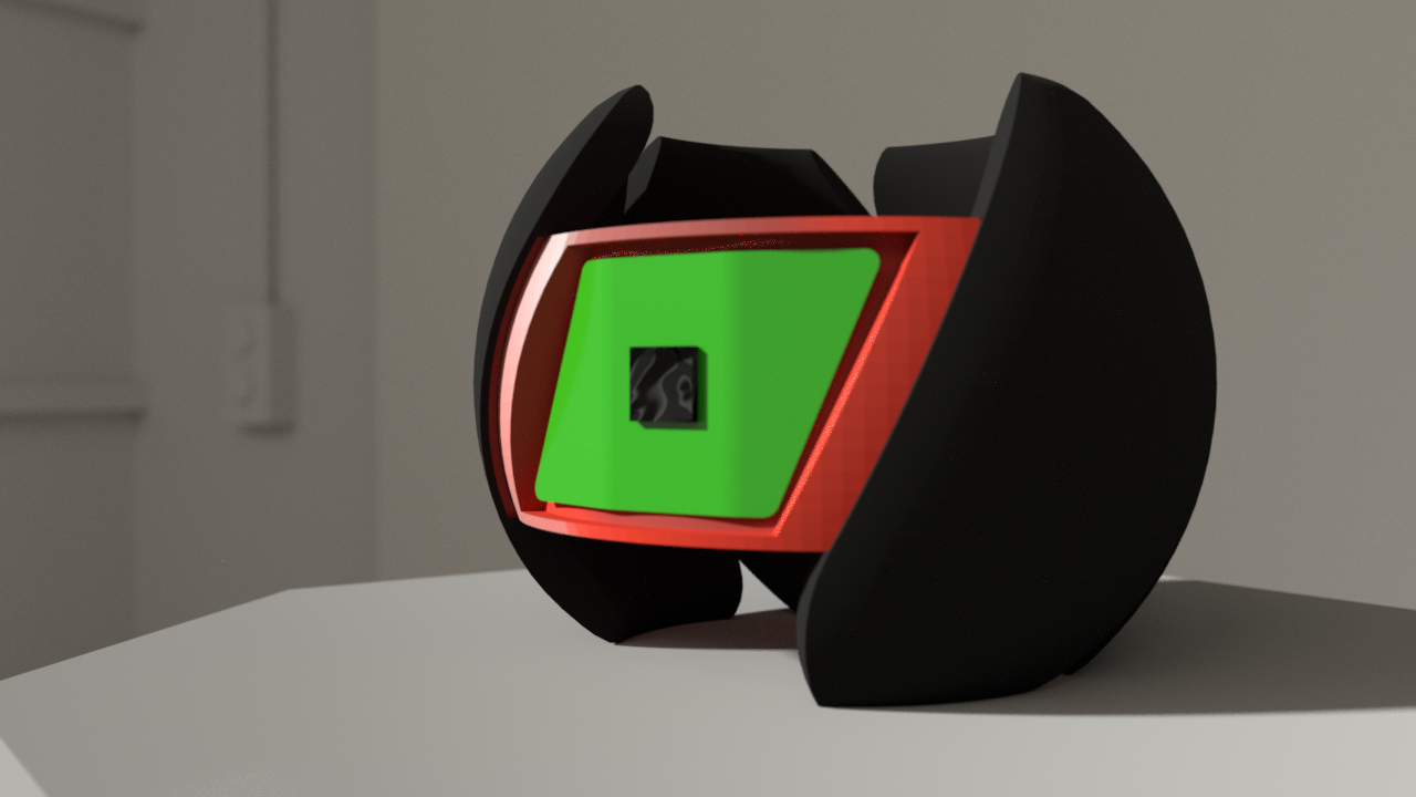
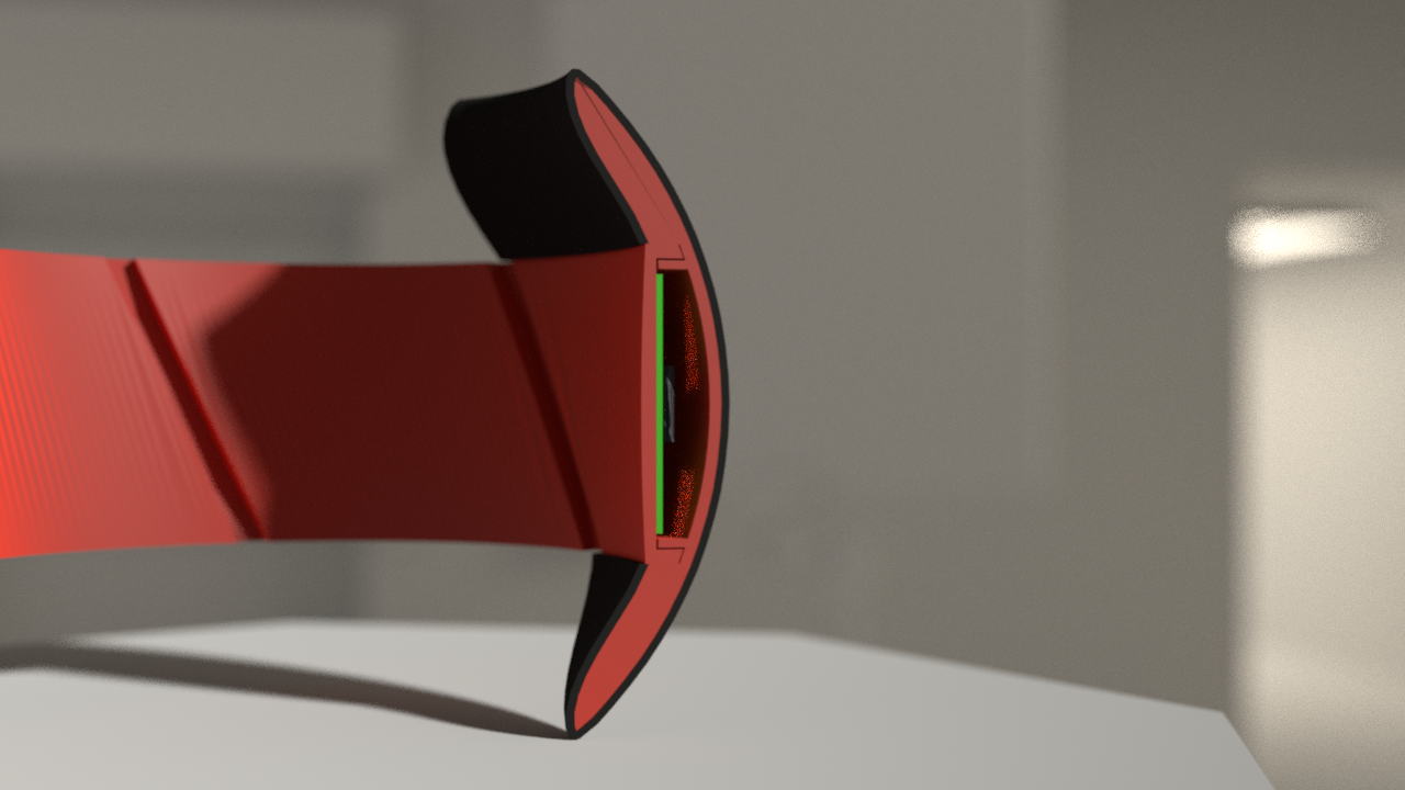
    On the cross section below the assembly mentioned is visible. PCB in green. You can see that ends of the module (will call it wings) can bend (flex) outward, but cannot inward (actually current visualization would be hard to bend, due to lack of indentations between module body and wings, I must yet figure out best layout of hinges). This ensures that QLBRD can be slid onto hand like a bracelet, but when held in hand will retain spherical shape. Wings, while rather tiny (approx 20x15x3mm inside) can contain tactile switches, 40mA LiPo batteries, micro USB socket and anything that could fit such space. I also consider leaving some little inward flex capability in some modules and with help of smd microswitches plan to turn certain wings into buttons.

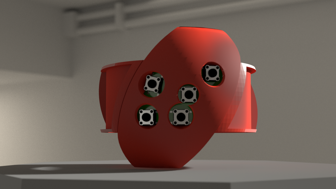
    Right, buttons. Some modules (depending on their position, they must fall under fingers or thumb) contain buttons. First version will use simple micro tactile switches. They fit. However I think of using some more sophisticated solution. Thumb can operate either buttons or a 4 way micro switch (joystick). Flexible wraps on such modules can have protrusions indicating their position. You can see how it's going to look on below render (without protrusions).

    QLBRD can contain many types of modules, not only logic, bluetooth and buttons. Also displays, gsm and others. Soon (when some modules I ordered arrive) will show their renders (must measure them and see what I can strip, bend, resolder :) ).

  • Picking frame ring diameter

    dhg08/25/2018 at 06:34 0 comments

    Today I attempted (with success) to find out what is the optimal internal diameter of QLBRD. As it's supposed to fit as a bracelet there's a hard limit set by average wrist size. After measuring my own wrist and few others I found out that 6.5 cm is around the size that should fit in all cases (without right end of Gauss curve ofc). 

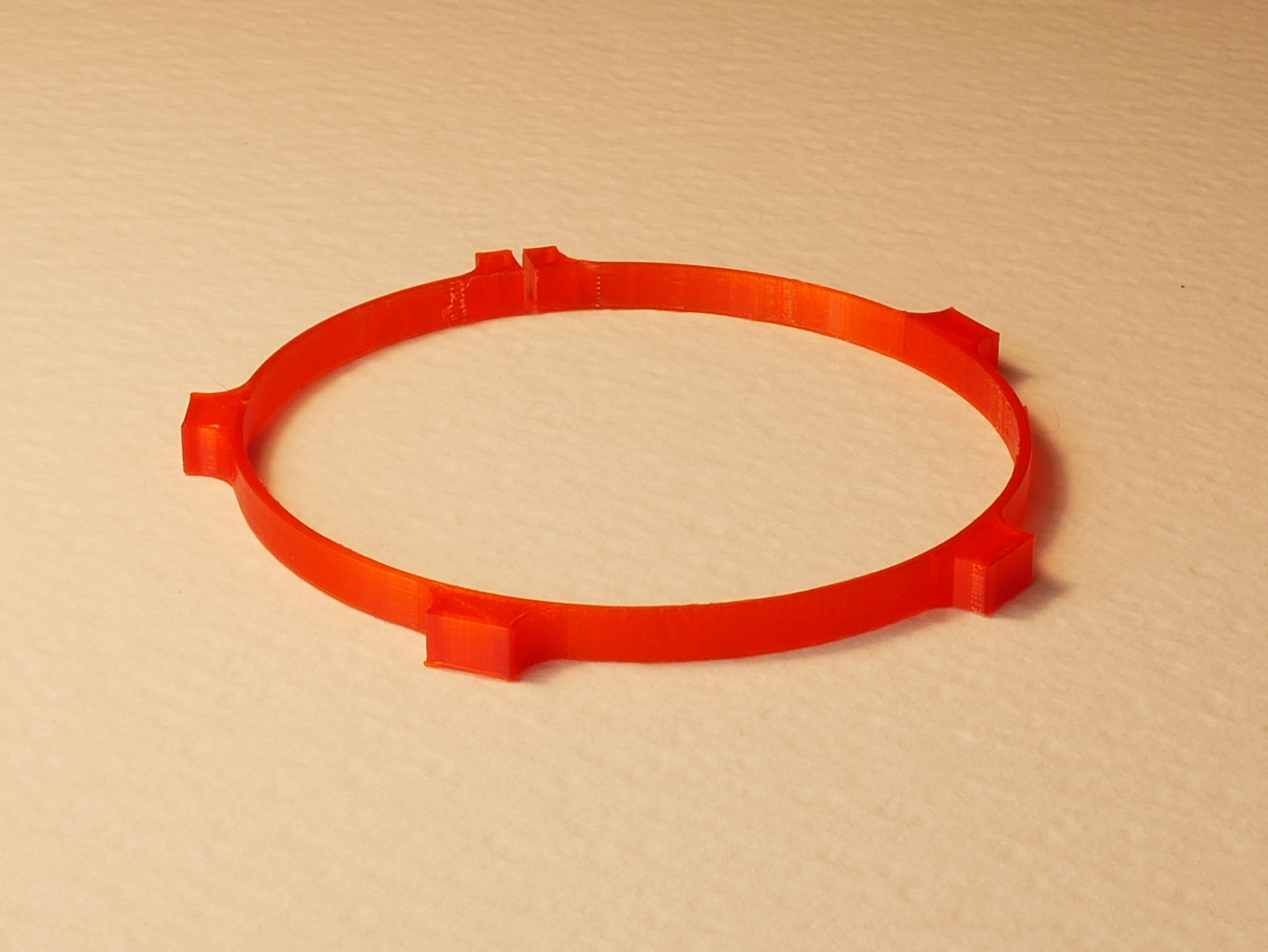
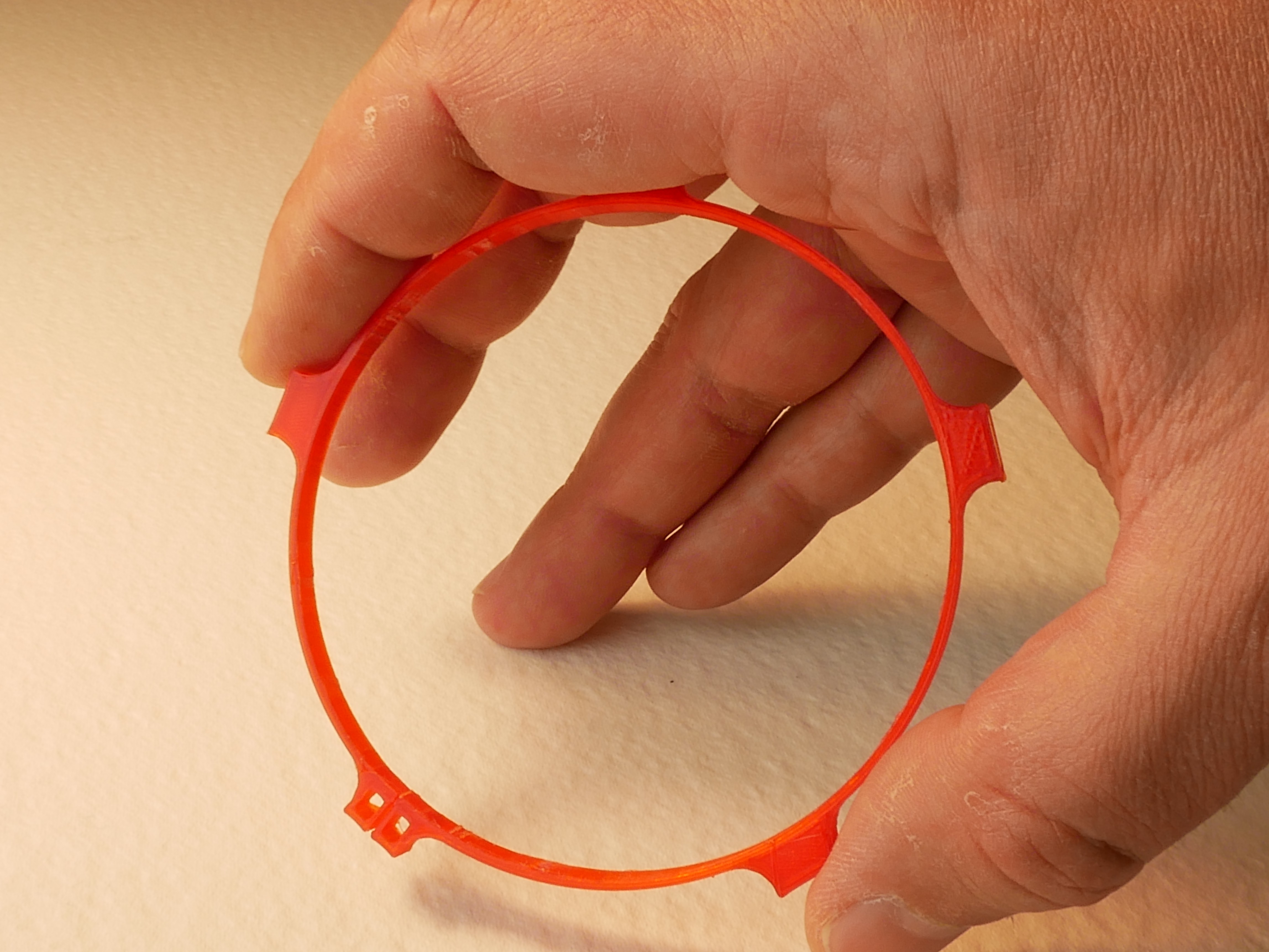
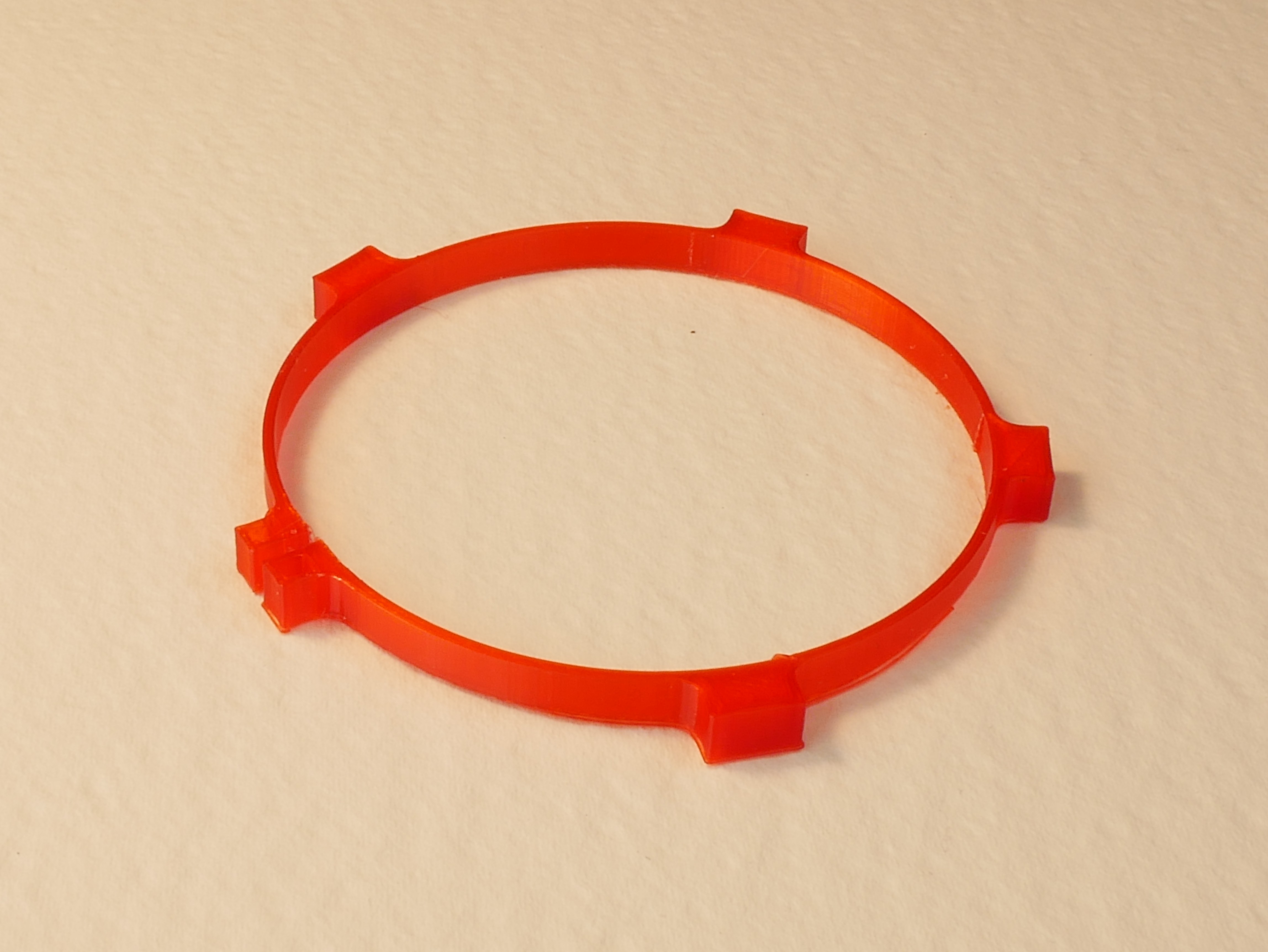
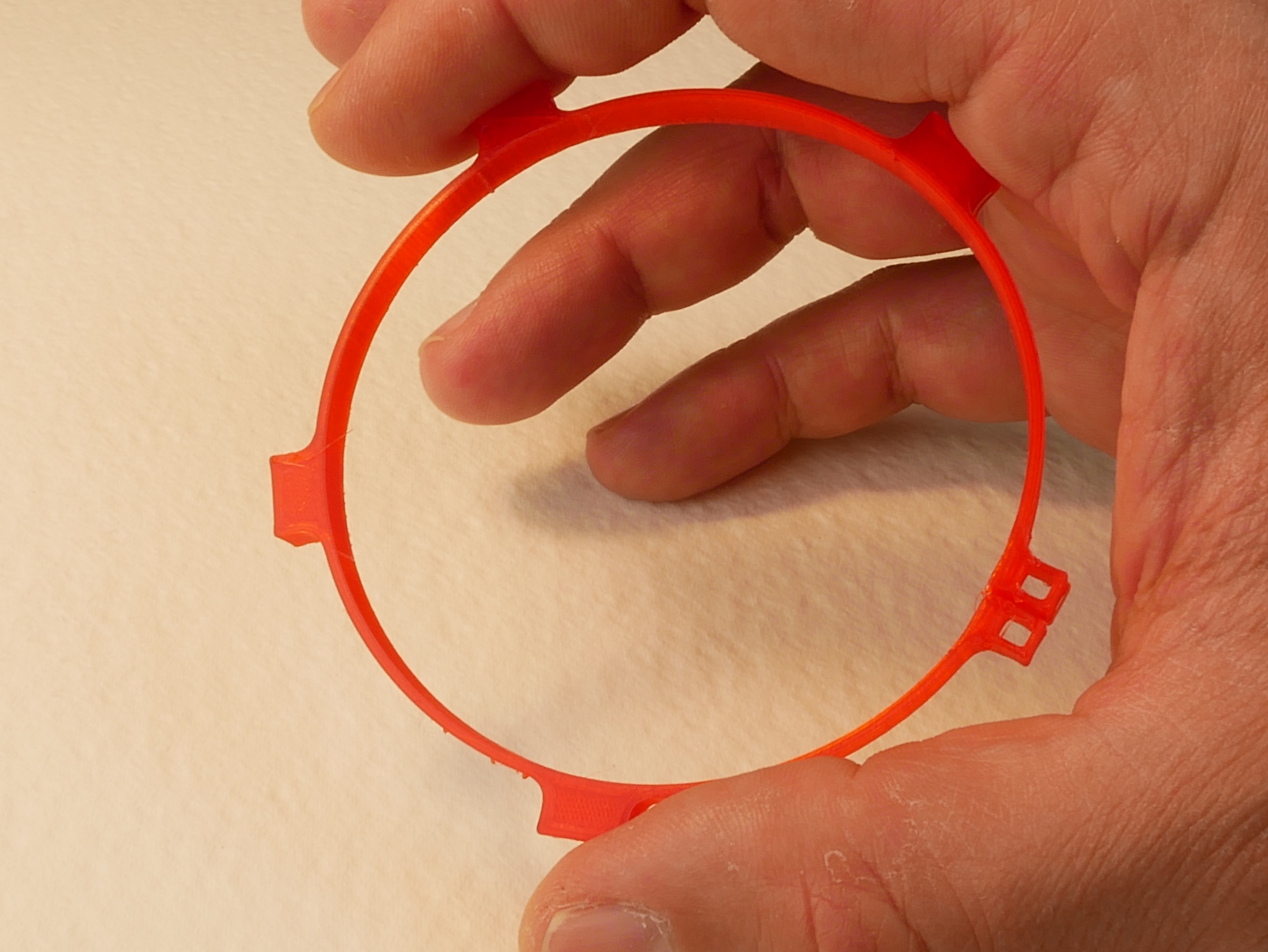
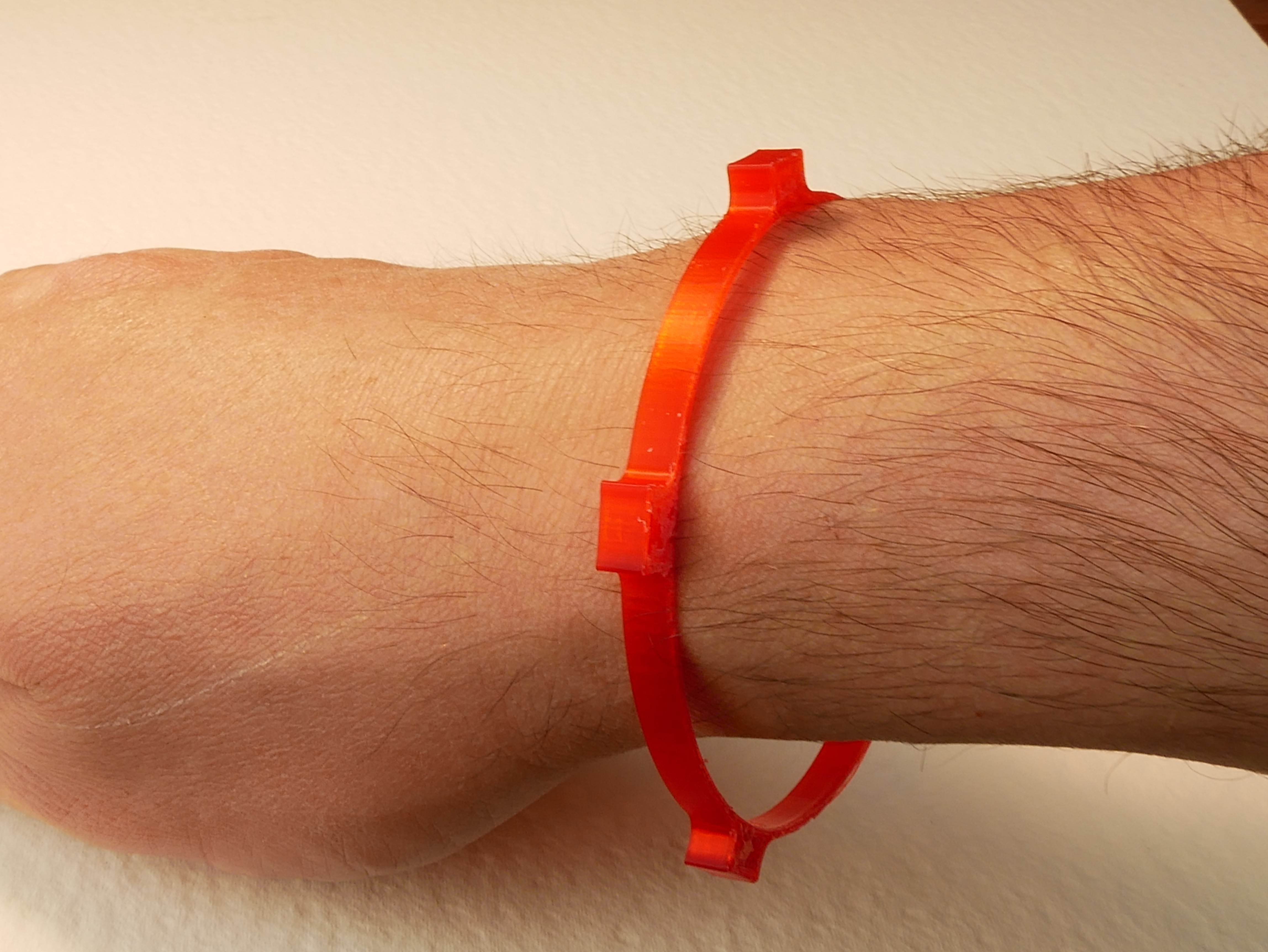
    As I wasn't sure about actual feel and ability to spread enough while passing a palm I prepared two samples (6.5 and 7.7mm in diameter) of internal frame ring. These samples aren't actual ring, they are only cross sections of rough models. They measure 1/6th of height of actual ring. One feature worth mentioning is a split on one of protrusions. It will host small rare earth magnets that will act as a clasp.

    One other dimension to note - 1.2mm for ring wall. Smallest meeting two conditions: to be durable enough and flexible at the same time. Smaller values tend to be very fragile when it comes to 3d printing.

    One last thing to mention before showing photos - the ring is here for two main purposes. It gives QLBRD its spherical shape (not quite spherical, rather distorted toroidal...) and provides common power data lines (on kapton based PCB).
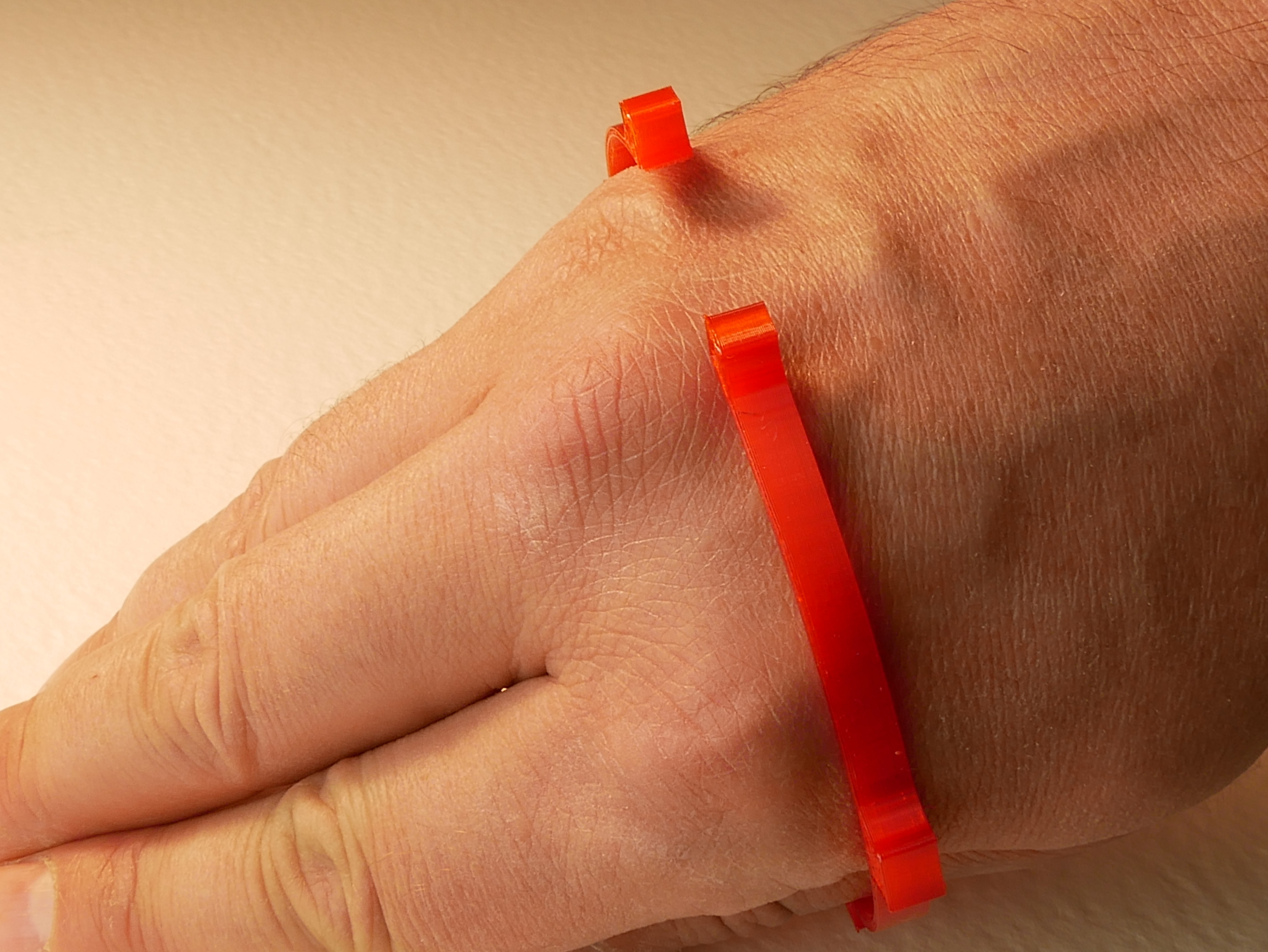
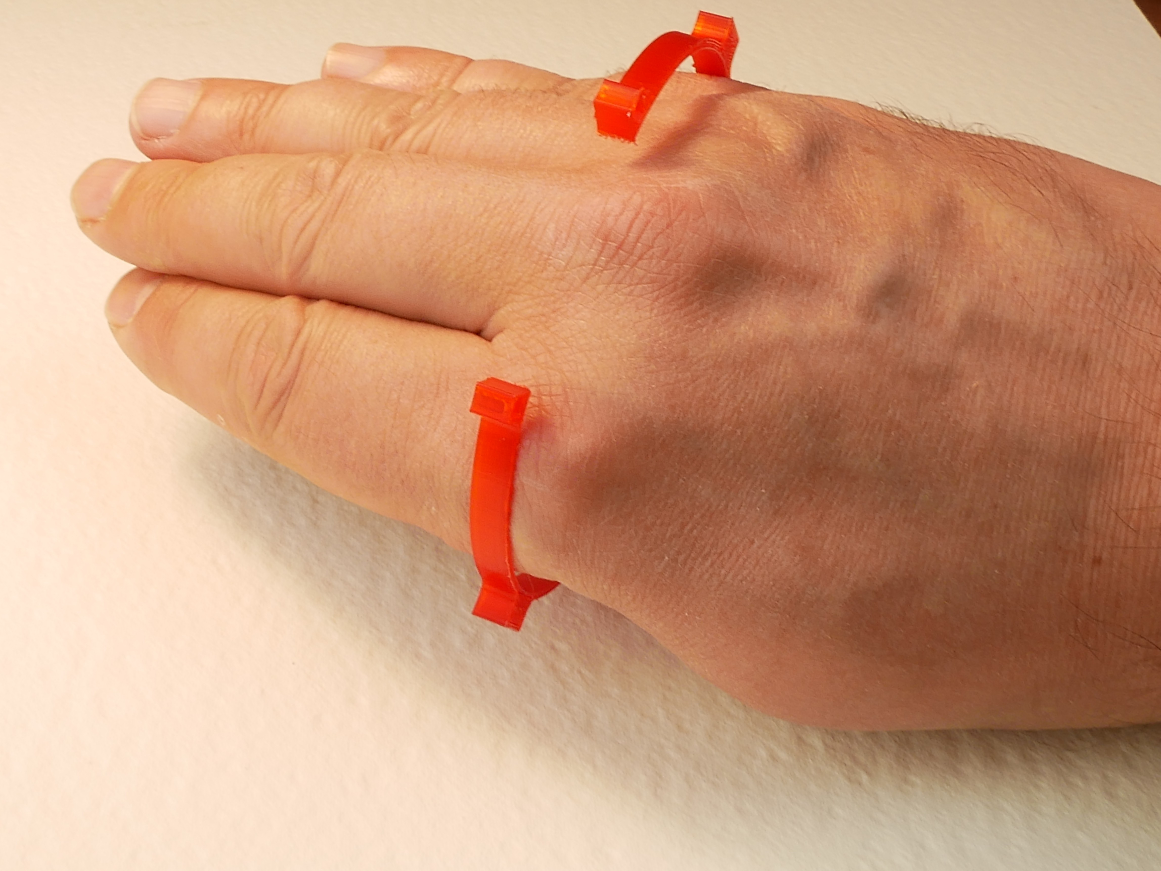
    Tested both diameters on mine and others hands (however post only mine, not for sensitive eyes). Both fit and flex without a hassle. The bigger one is just too big to my taste. Later in process I'll prepare two or more size versions, but for now I'll go with the smaller, 6.5mm one.

    The bigger one

    Passes well

    But little too big as the ball will be 12mm bigger than that.

    Smaller one, less space inside the ball, but far more comfortable to hold.

    As can be seen here.

    Spreads wider and deforms more but in acceptable range (or predictions as to said range).

    Leaves still a lot of space for free movement, doesn't compress hand from any side.

  • First steps - looking for fast PCBs prototyping

    dhg08/24/2018 at 05:56 0 comments

    One of first issues I stumbled upon when preparing this project was whether I'll be able to create custom PCBs in a fast and precise way. There are three reasons why I needed such solution:

    1. QLBRD modules have limited internal space, in most cases off-the-shelf components just could not fit in. Moreover, spaces aren't regular but mostly curvy. Also oftentimes first prototypes do not fit well or have missing features as we, humans are fallible . Thus the best choice is to have fast prototyping line for custom boards (on flexible base) and resolder elements on them;
    2. I have no fully blown lab as making things is my hobby. Out of simple solutions available for guys like me none was precise enough to give decent results. UV sensitive paint + etching solution works best, but often results in small defects due to side light scattering. So, I decided to try something else.
    3. PCBs can be ordered with professionals, but I live in Sweden where distances aren't negligible, things aren't readily available off-the-shelf even in online shops and delivery times aren't the shortest (I still wait for Blufruit LE to come). 

    So, I decided to give engraving a try. In a matter of minutes I turned a spare 3d printer nozzle into engraving tip using a piano wire I found stuffed in mess. The rest is shown in the video. And results are better than expected.

View all 9 project logs

  • 1
    [ optional ] Experiment with different parametrically designed shapes of QLBRD modules

    Have Blender installed with Sverchok addon. Knowledge how to use Blender is highly recommended.

    Take nodes.blend file from files in this project. Run it.

    In Compositor view you can switch to Sverchok nodes. Open a node tree called NodeTree :) . It contains scripted node with my script loaded, solidify node and BMesh visualization node. All connected.

    By changing parameters of Scripted Node you can change shape, number, deformations of all modules. If provided with high enough number of vertical and horizontal divisions (parameters 1,2,3) the resulting mesh is a good base to make final, printable part.

    If curious, take a look into the file that feeds the node. I did my best comment as much as possible. And you can ask me directly as well.

View all instructions

Enjoy this project?

Share

Discussions

Similar Projects

Does this project spark your interest?

Become a member to follow this project and never miss any updates