 igorfonseca83
-
1Tools and Materials
The following tools and materials were used in this project:
- Solder iron and wire. I had to solder some terminals to Nunchuk's wires in order to connect it to the Arduino;
- Shrinking tube. Some pieces of shrinking tube were used for a better isolation of the conductors;
- Screwdriver. The structure is mounted using some bolts and nuts;
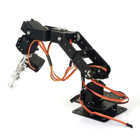
- 6-axis mechanical desktop robotic arm (link). This awesome kit already comes with several components as described bellow. It's reliable and easy to assemble;
- 12V power supply (2A or more);
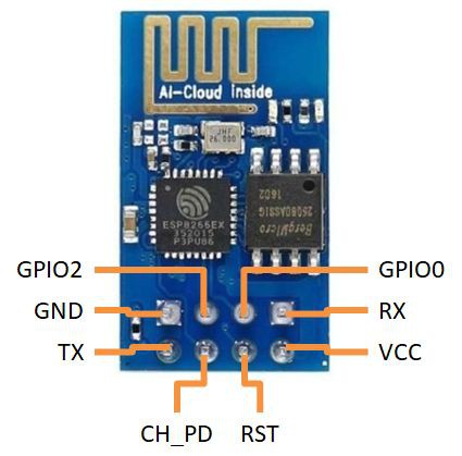
- ESP8266-01 (link / link). It's used as a 'WiFi modem'. It receives signals from the control interface to be performed by the Arduino;
- Male-female jumper wires (5 wires);
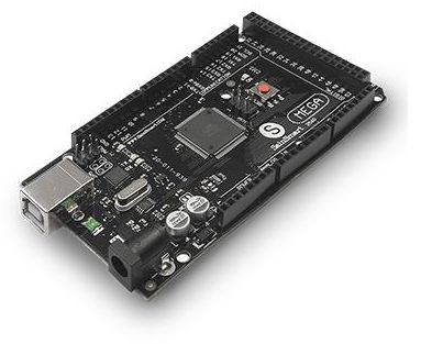
- Arduino Mega (link / link / link). Notice that the robotic arm kit I've used also has a board and controller bundle that already comes with this Arduino board. If you you're not using on of those kits, you might use other Arduino boards as well;
Sain Smart 6-axis mechanical desktop arm already comes with the following components:
- Arduino Mega 2560 R3 (link)
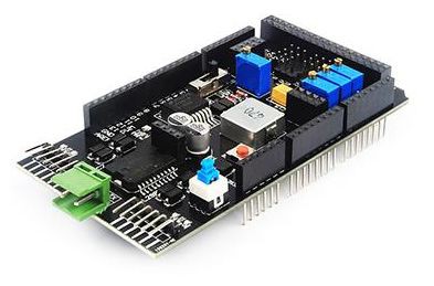
- Control board shield (link)
- NRF24L01+ Wireless Transceiver Module (link)
- MPU6050 3-axis gyroscope and a 3-axis accelerometer (link)
- 71 x M3X8 screw
- 47 x M3 nut
- 2 x U bracket
- 5 x servo bracket
- 4 x 9kg servo (link)
- 2 x 20kg servo (link)
- 6 x metal servo tray
- 3 x U bracket
- 21 x right-angled bracket
- 3 x flange bearing
- 1 x gripper
You might find other robotic arm kits online (link), or even design your own. There are some awesome projects you can 3D print, for instance.
In the next step I'll show you how to assemble the arm kit before wiring up the circuits. If you doesn't have a similar kit, feel free to jump some steps. You can use another robotic arm kit, assemble it and jump directly to the electronics and programming steps.
![]()
![]()
![]()
-
2Assembling the Robotic Arm
In this step I'll show you how to assemble the arm kit (mechanical parts) I've used (link). If you doesn't have a similar kit, feel free to jump some steps. You can use another robotic arm kit, assemble it and jump directly to the electronics and programming steps.
- The first part to be assembled is the base of the robot. It's made of two U shaped brackets, joined back to back using four M3 bolts and nuts, as shown in the pictures;
- The first servomotor is mounted perpendicular to the base, using a servo bracket. This profile is attached to the base using four M3 bolts and nuts, as it's shown in the pictures. Servo #1 is place on it's top, and attached using four M3 bolts and nuts. A circular metal horn is attached to the servo axis. The kit comes with several plastic horns. They won't be used for assembling the robot.
- Another servo bracket is mounted perpendicular to the previous one. It's connected to servo #1 horn using four M3 bolts. Servo #2 is installed with four M3 bolts and nuts, and also uses a circular metal horn. An U bracket is then attached to the horn using four bolts. Notice that a M3 bolt is used oposite the servo axis. It gives stability to the structure. A bearing fits on this bolt, and it's locked in position using another M3 nut. This way the U bracket is tightly attached to servo #2 center axis.
- Another U bracket is mounted using four M3 bolts and nuts. On the other end, servo #3 is installed, using a circular metal horn and four bolts. A servo bracket is connected to the servo motor, and a L shaped profile is linked to the servo bracket using some bolts and nuts. Notice that another bearing is used oposite to the servo axis, as described before.
- Another U bracket is connected to the L shaped profile using a set of four M3 bolts and nuts. Similarly to the previous step, servo #4 is mounter to the U bracket using four bolts. Another servo bracket is connected to the servo.
- The fifth servo is connected perpendicular to servo #4 using another servo bracket, installed using four M3 bolts and nut.
- The gripper is then connected to servo #5 axis. On it's top, servo #6 is connected using some bolts, nuts and a metal horn. The gripper has some gears, which will turn the rotation of the servo into a linear movement of the gripper.
![]()
![]()
![]()
![]()
![]()
![]()
![]()
![]()
![]()
![]()
-
3Wiring Up the Circuits
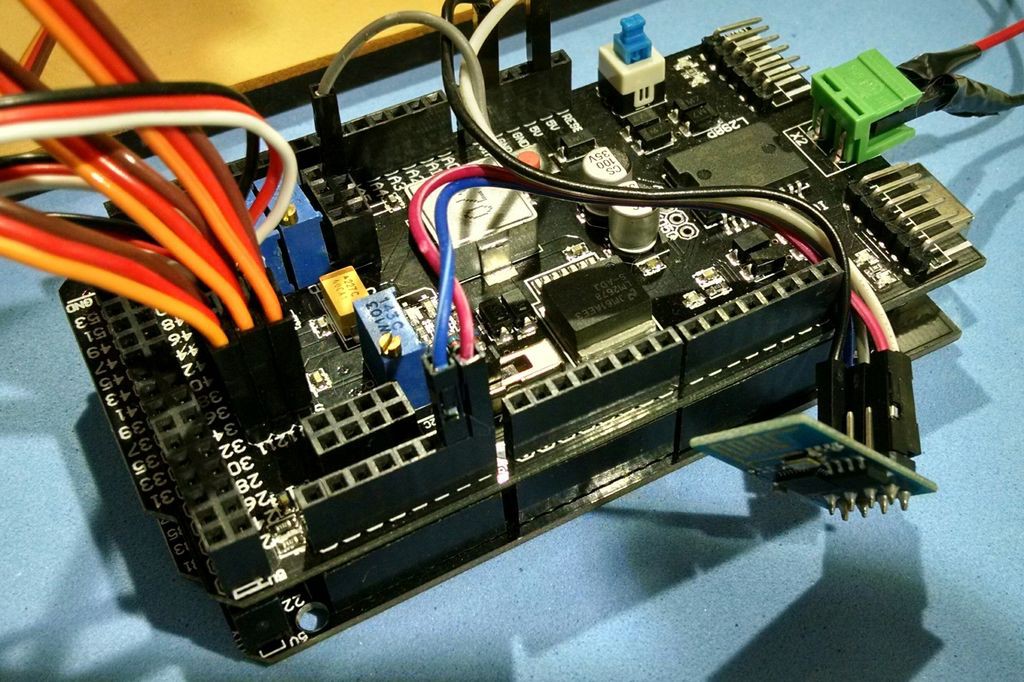
Once the structure is assembled, you'll be ready to wire up the circuits. I used the controll board shield that came along with my robotic arm kit. It makes the connection of the components easier, since it already comes with specific connectors for the servomotors, power supply, etc.
Unfortunatelly this controll board doesn't have a specific connector for the ESP8266. So I had to use some jumper wires to connect that Wi-Fi module to my Arduino Mega.
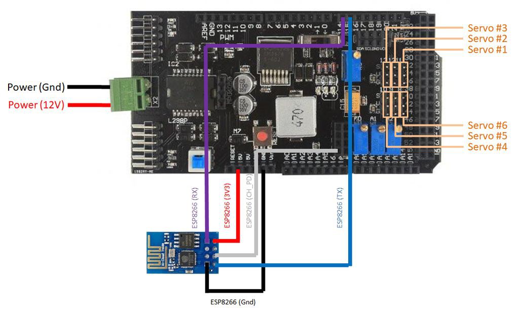
Connect the components as follows:
ESP8266:
- ESP8266 RX => Arduino Mega Pin 14 (on the shield)
- ESP8266 TX => Arduino Mega Pin 15 (on the shield)
- ESP8266 Vcc => Ardino Mega Pin 3V3 (on the shield)
- ESP8266 Gnd => Arduino Mega Pin Gnd (on the shield)
- ESP8266 CH_PD => Arduino Mega Pin 3V3 (on the shield, in the connector reserved for the 24L01 module)
You'll notice that the servo control shield has two pins labeled as 5V. Although, one of then is actually a 3.3V pin. Test it with a voltage meter.
Servos:
- Control shield terminal 11 => Servo #1
- Control shield terminal 12 => Servo #2
- Control shield terminal 13 => Servo #3
- Control shield terminal 8 => Servo #4
- Control shield terminal 9 => Servo #5
- Control shield terminal 10 => Servo #6
If you're not using the control shield, you should use the following pin configuration:
- Arduino Pin 11 => Servo #1 (Sgn)
- Arduino Pin 12 => Servo #2 (Sgn)
- Arduino Pin 13 => Servo #3 (Sgn)
- Arduino Pin 8 => Servo #4 (Sgn)
- Arduino Pin 9 => Servo #5 (Sgn)
- Arduino Pin 10 => Servo #6 (Sgn)
- Arduino Gnd => Servos Gnd
- 6V Power supply => Servos Vcc
You'll also need to connect an external 12V power supply. I suggest one with more than 2A output. The servos consume a lot of power, and if the power supply is not powerfull enough, the servos will vibrate and get really hot. They will also lose their strenght.
Don't connect the power source until you've uploaded the Arduino code (shown in later steps). There's a power button on the shield. Keep it on the off position.
Plug an USB cable on the Arduino and proceed to the next step.
Warning! You'll notice I've connected my ESP8266 RX/TX pins directly to the Arduino TX/RX pins. It worked for me, but I don't recommend doing the same. ESP8266 works with 3.3V, and the Arduino pins run on 5V. Some say it might burn your ESP8266 module (although I've tested it several times, and had no issue). You might use a voltage divider or a voltage level shifter if you want to convert 5V to 3.3V.
![]()
![]()
![]()
-
4Setup Arduino IDE
Now that the hardware is ready, it's time to work on the Arduino code.
1. Download and install Arduino IDE latest version You can find the latest version for Windows, Linux or MAC OSX on Arduino's website:https://www.arduino.cc/en/main/software
Download it for free, install it on your computer and launch it.
No additional library was used for the communication between the Arduino and the with ESP8266 module. Please check the baudrate of you ESP8266 and set it properly in the code.
-
5Arduino Code
Download Arduino code (browser-controlled-arm-v3.ino) and replace the XXXXX by your wifi router SSID and YYYYY by router password. Connect the Arduino board to your computer USB port and upload the code.
Once the circuit is powered, the arm will move to the starting position, and the ESP8266 will try to connect the Wi-Fi network.
Warning: when the code starts running, the robotic arm will move really fast to it's initial position. Be careful not to get hurt or damage nearby equipment during startup!
You'll possibly have to replace the starting angle of each servomotor depending on how your servos where mounted.
-
6HTML Interface
![]()
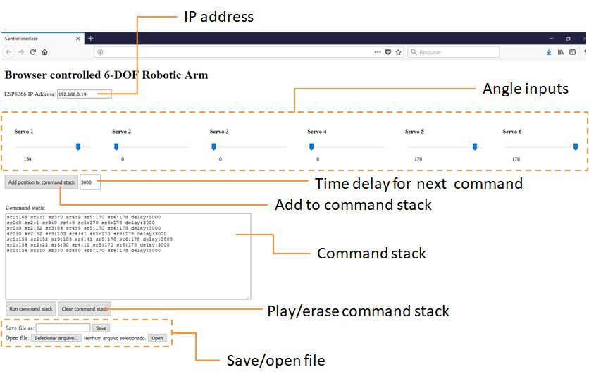
A simple control interface was designed using html and Javascript. Download it, unzip it and launch it in your web browser. I've tested it in Firefox and Google Chrome browsers.
In order to send commands to the Arduino, user shall enter the IP address assigned to the ESP8266. As it was described before, you can get it using the Serial monitor. Fortunatelly, the IP tends to be repeated itself in the following connections.
On this controll interface, the user can select a given angle for each joint using some sliding bars. Current angle for each servo is shown under each bar.
An Add position to command stack button aloows the user to store current position of the arm on a Command stack in a text box. This way, a sequence of position can be stored, with a configurable delay between each movement.
Each command is define as sr1:angle1 sr2:angle2 sr3:angle3 sr4:angle4 sr5:angle5 sr6:angle6 delay:time. Angles are represented in degrees and time in miliseconds. User can also edit the commands manually on the text box.
Run command stack plays the sequence of commands stored on the command stack. Clear command stack erases the list of commands. User may also save the command list (in a text file) and load it later. This way, one may store sequences of commands and repeat them.
-
7Have Fun!
Plug the USB cable on your computer, open the serial monitor and power up the robot.
It will automatically connect your WiFi network and show it's IP address. Save that number. You may now remove the USB cable (and even reset the Arduino). It will probably use the same IP address if you try to connect it again to the same network.
Open the interface on your web browser, and enter the IP address you've seen before. The computer have to be connected to the same WiFi network.
Select the angle for each joint and add to a stack of commands. A delay might be used between any two commands. Notice that the delay have to be large enough to ensure the previous command has ended (the robot has reached last set point) before a new command is sent.
You can save the stack of commands on a .txt file and use it later.
Save some moves, play them and have fun!
If you liked this tutorial, please click the 'like' button and share it with your friends! :D
![]()
![]()
WI-FI BROWSER CONTROLLED ROBOTIC ARM
Control your robotic arm remotelly using an ESP8266 WiFi module, from a simple html interface!


Discussions
Become a Hackaday.io Member
Create an account to leave a comment. Already have an account? Log In.