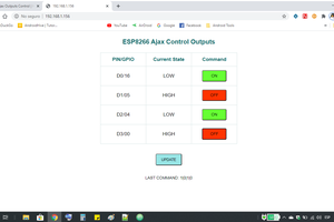
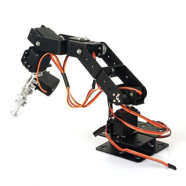
Control your robotic arm remotelly using an ESP8266 WiFi module, from a simple html interface!
To make the experience fit your profile, pick a username and tell us what interests you.
We found and based on your interests.
browser-controlled-arm-v3.inoArduino Codeino - 5.58 kB - 08/26/2018 at 12:50 |
|
|
interface.zipHTML interfacex-zip-compressed - 35.36 kB - 08/26/2018 at 12:50 |
|
The following tools and materials were used in this project:
Sain Smart 6-axis mechanical desktop arm already comes with the following components:
You might find other robotic arm kits online (link), or even design your own. There are some awesome projects you can 3D print, for instance.
In the next step I'll show you how to assemble the arm kit before wiring up the circuits. If you doesn't have a similar kit, feel free to jump some steps. You can use another robotic arm kit, assemble it and jump directly to the electronics and programming steps.
In this step I'll show you how to assemble the arm kit (mechanical parts) I've used (link). If you doesn't have a similar kit, feel free to jump some steps. You can use another robotic arm kit, assemble it and jump directly to the electronics and programming steps.
Once the structure is assembled, you'll be ready to wire up the circuits. I used the controll board shield that came along with my robotic arm kit. It makes the connection of the components easier, since it already comes with specific connectors for the servomotors, power supply, etc.
Unfortunatelly this controll board doesn't have a specific connector for the ESP8266. So I had to use some jumper wires to connect that Wi-Fi module to my Arduino Mega.
Connect the components as follows:
ESP8266:
You'll notice that the servo control shield has two pins labeled as 5V. Although, one of then is actually a 3.3V pin. Test it with a voltage meter.
Servos:
If you're not using the control shield, you should use the following pin configuration:
You'll also need to connect an external 12V power supply. I suggest one with more than 2A output. The servos consume a lot of power, and if the power supply is not powerfull enough, the servos will vibrate and get really hot. They will also lose their strenght.
Don't connect the power source until you've uploaded the Arduino code (shown in later steps). There's a power button on the shield. Keep it on the off position.
Plug an USB cable on the Arduino and proceed to the next step.
Warning! You'll notice I've connected my ESP8266 RX/TX pins directly to the Arduino TX/RX pins. It worked for me, but I don't recommend doing the same. ESP8266 works with 3.3V, and the Arduino pins run on 5V. Some say it might burn your ESP8266 module (although I've tested it several times, and had no issue). You might use a voltage divider or a voltage level shifter if you want to convert 5V to 3.3V.
Create an account to leave a comment. Already have an account? Log In.
Become a member to follow this project and never miss any updates