-
1Diagrams
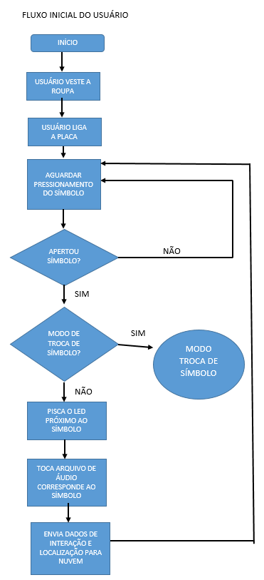
To help understand the operation of the vest we will explain its use by means of three diagrams:In this first step we define three diagrams with the interation flux. The first one is when the users wear and touch a symbol in the vest
![]()
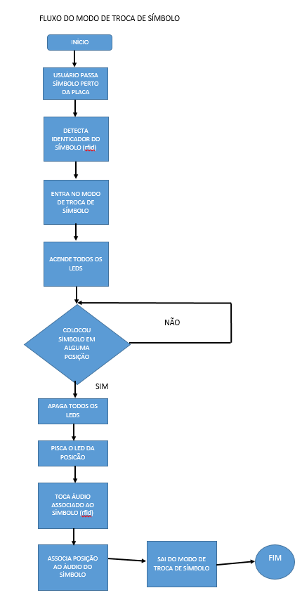
The second diagram shows when the caretaker replaces the button in the vest with a new one
![]()
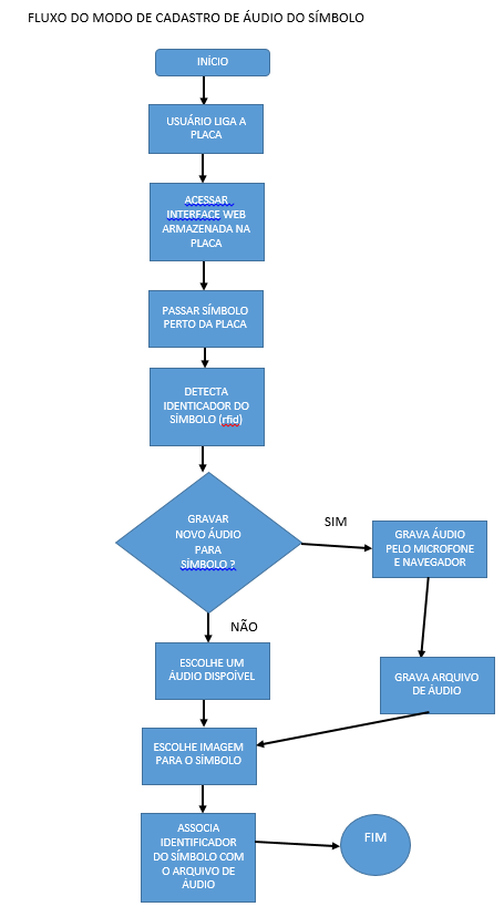
The third diagram shows the steps to register a new image and sound to represent a new symbol in an existing physical button.
![]()
To help understand the operation of the vest we will explain its use by three diagrams:
Diagram 1: This flow represents the initial use of the clothing describing the steps necessary to dress it and access the audio already registered.
Diagram 2: This diagram shows the steps to change one of the existing pads so that another symbol / sound is placed on the vest.
Diagram 3: This diagram shows the steps to change the audio associated with an existing cushion. This flow was not implemented in version 1.0 of the vest.
-
2Software
We used the following softwares to program the Vest:
The external dependencies of the project are the Arduino library to handle the RFID reader module, the Python library twx.botapi to interact with the Telegram and the PySerial library to read / write data through the serial port with Python. The Python libraries can be installed using the pip package manager.
All the source code files are available in the project's git hub page: https://github.com/pichiliani/CoCoA
-
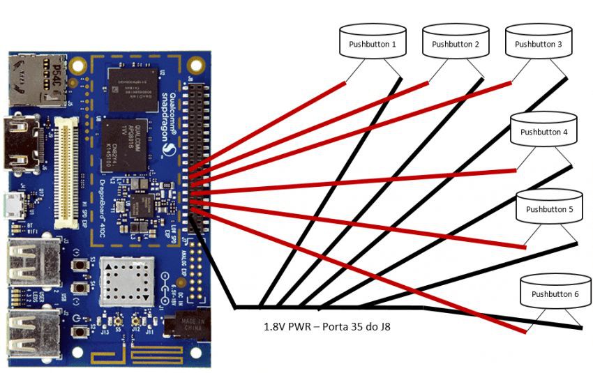
3Physical connections
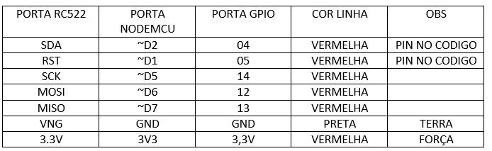
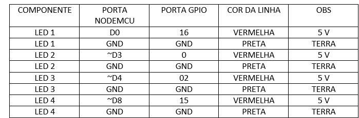
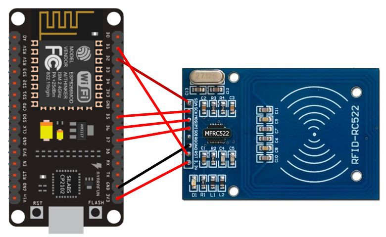
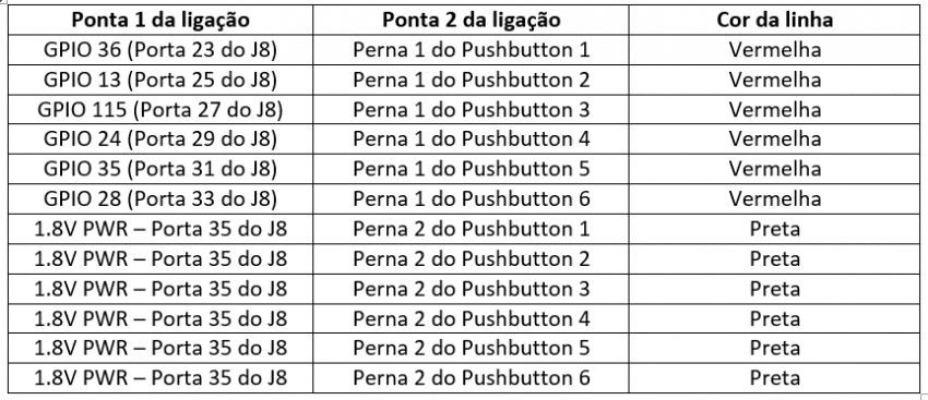
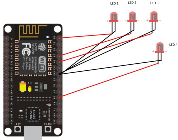
The following images describe the physical connections of the boards, sensors, push buttons and other hardware. We also provide tables with the correct port numbers, names and wire colors.
![]()
![]()
![]()
![]()
![]()
![]()
The architecture of the CoCoA project is based on the DragonBoard 410C card, an Arduino NodeMCU 8622, the RFID reader sensor, LEDs, push buttons and a sound box. An integration with a Telegram bot called ProjectCoCoABot is also done, which sends a message with the generated audio each time one of the buttons is pressed.
We chosed to connect the RFID reader and the LEDs on theAarduino and then upload the code that is in the /CocoaNodeMCUServer folder on GitHub. Connection diagrams of both the LEDs and the RFID reader are shown in the figures that illustrate this step.
We also need to connect the push buttons with the DragonBoard board. This diagram and table are also shown in pictures that accompany this step.
-
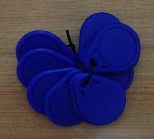
4Cushion pads
![]()
First we must construct the pads that will hold the symbols and the RFID tags. There are several symbols and systems for non-verbal communication, but we can indicate thePECS as a good starting point. This system has several symbols that can be printed and placed on the cushions.The cushions have about 10x10cm and were filled with cotton. It is important to remember to place inside each cushion one of the keyrings that contains the RFID tag so that it is possible to identify each of the cushions and their respective sounds.
In front of the cushion we put the same symbol twice: one with the image facing up and the other facing down. This way it is possible for the wearer of the vest to observe which symbol was pressed. Do not forget to place a piece of one side of the velcro on the back of the cushion so that it is possible to attach and remove the cushion pad.
-
5Vest construction
![]()
![]()
The next step is building the vest. To do this use a male child vest pattern and cut the fabric so that there is a lining. In these following links we can find some patters of vests to print:It is important to define the location on the front where the cushions will fit. In these places we must put parts of the Velcro so that the cushions are fitted correctly. Still in the front we can make the holes to place the part that shines from the LEDS just above the cushions.
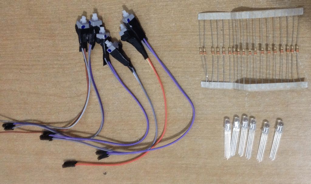
At the back of the vest site we need to fit the LEDs and each of the push buttons. It is important to fit the push buttons so that they are just behind the Velcro . This way as soon as the user presses the center of the pad it will force the "hard" part of the pad (the key ring with the RFID tag) and press the push button.
We recommended to attach all internal parts of the vest (leds, resistors, push buttons and wires) using the hot glue. The connection of the wires can be made with welding iron + insulation tape. Another alternative to avoid using solder is hot glue or transparent nail enamel.The next part of the vest is to build small pockets to hold inside the components of each cushion. Also create a pocket at the front of the vest closer to hold the sound speaker box. It is advisable to put several strips of Velcro to close the vest at the waist so it be tight at the user waist just like an aeroplane safety vest.
The wires that connect the components (LEDs and push buttons) of each touch area should be grouped two by two. This way we will have six strips with two cables each. Each cable has two wires: the positive and the negative. Mark the order of the cables and which component is connected to each cable (led or push button). We recommend passing the strands of yarn across the shoulders dividing the wires into two groups of three.
Once the cables and wires are connected we can close the vest by placing the liner. To finish, create a horizontal pocket on the back of the vest to hold the cards (NodeMCU and DragonBoard), the USB sound connector and the battery that will connect to DragonBoard.
-
6Final connections and testing
Once the vest straps are already passed to the back, it is necessary to make the connections with the boards. There are 12 connections required for the push buttons (6x2) and 12 connections for the LEDs.
Additional care must be taken to connect the wires that carry the ground signal (GND - Groud) to the LEDs, as all six "legs" of the LEDs must be connected to the same wire. Similarly, the ground (GND) connectors of the pushbuttons should be connected to the same wire.
Finally, connect the dongle to the USB port and plug the adapter into the sound speaker, which should be placed in the front pocket of the vest . Plug the USB cable into the NodeMCU and into the other USB port on the DragonBoard 410c card. Finally, connect the battery pack to the power pin and start the CoCoaServer.py program on the DragonBoard board as sudo (use an SSH connection or connect a monitor + keyboard + mouse directly to the board):
sudo python CoCoaServer.pyEach button pressed will display a message on the console of the card, the corresponding audio will be played and the led associated with the cushion will be touched.
For a summary of the project see the video indicated in the video below:
Alternative Communication Vest
The CoCoA Project is a wearable vest connected to the internet that assists people with speech or non-verbal disabilities.

Discussions
Become a Hackaday.io Member
Create an account to leave a comment. Already have an account? Log In.