Leonardo Gomes
-
Design of the touch stimulator
08/27/2018 at 04:07 • 0 commentsThe touch stimulation interface was designed for providing the feeling of being touched remotely. This interface is wearable and its output, or stimulation response, depends on the touch detected by the sensitive interface. The design of the touch stimulation interface considered meeting the requirement that it should create a sensation of a moving touch through the skin, not only by mechanical stimulation, but also by other stimuli. Besides the vibrations, the interface is able of stimulating thermally and electrically the skin and muscles.
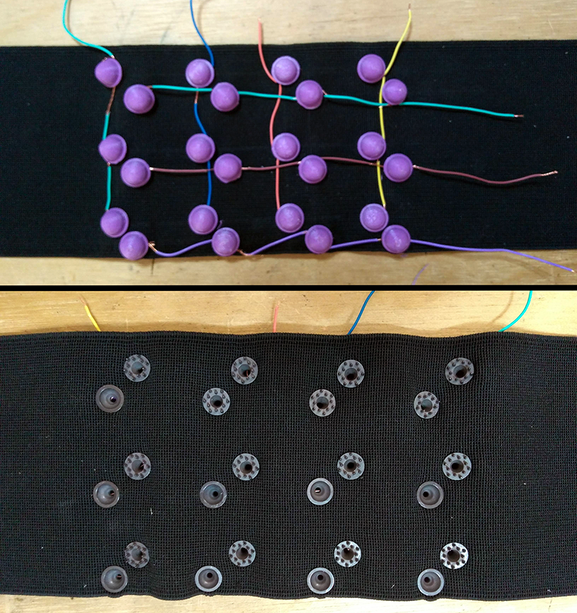
For covering a relatively large surface of the skin while the interface was being worn, we decided to place the electrodes in a matrix pattern, where each element of the matrix is a pair of electrodes. We used two types of electrodes: 15 spike dry electrodes and 9 wet electrodes, combined in a total of 12 pairs. The using of spike dry electrodes was preferable in this design, because those electrodes don’t need the use of conductive gel and have a better performance when in contact with hairy skin, but the total required number wasn’t available at the moment of building the prototype. The electrodes of the lines and columns (3x4) were connected to each other respectively, and a 3D printed cap was fitted over the head of each electrode and wire, keeping the connection safe and fixing the set in the elastic fabric.
![]()
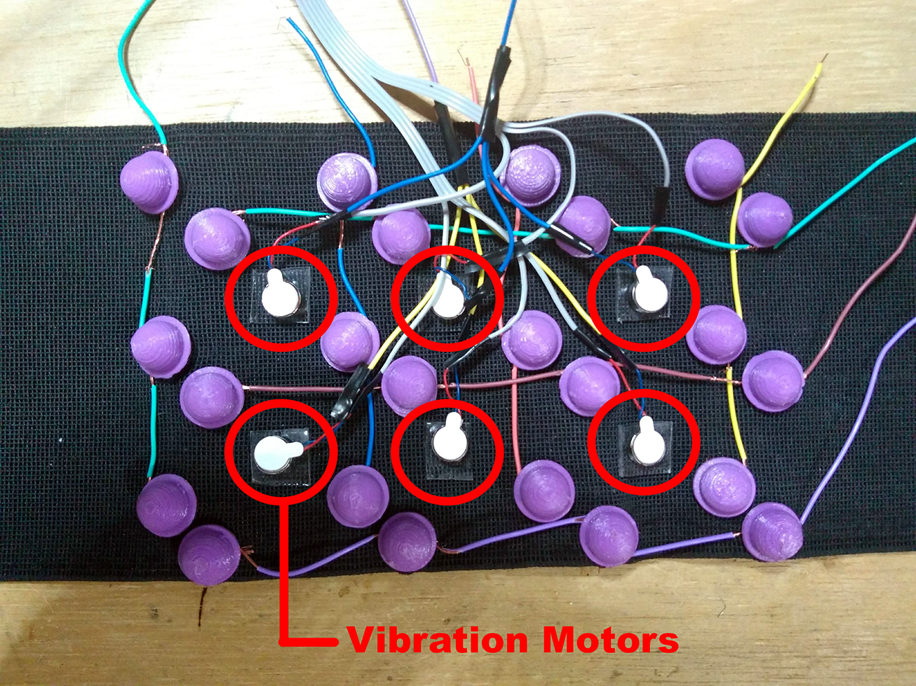
For creating the sensation of a moving touch, we change the pair of conducting electrodes by changing what line and column are active, and the electrical stimulation will occur in the closest pair of electrodes. In addition to the electrical stimulation, we included 6-coin vibration motors, as shown in the figure below, between the electrode pairs. The motors were used for creating an additional sensation of touch, for example simulating the moment that the finger touches the skin or when the finger slides from one point to another.
![]()
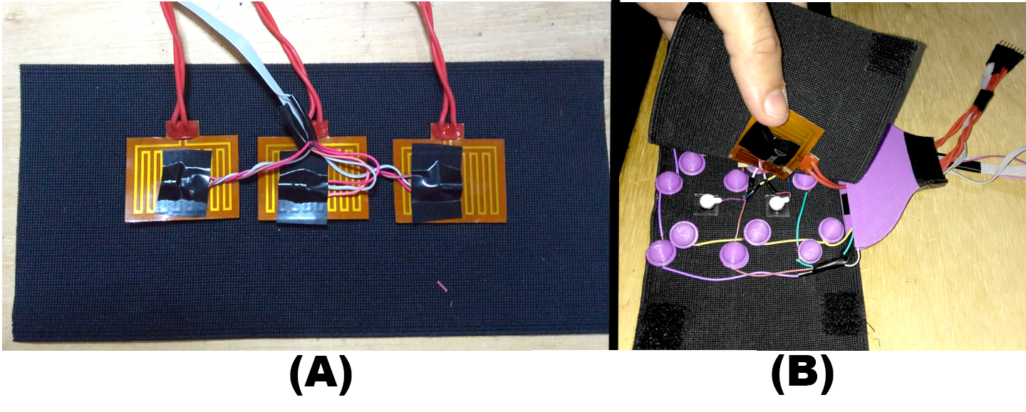
The third touch stimulation method is by thermally stimulating, simulating the temperature of the human body. For creating this effect, we used 3 flexible heaters, or polyamide heating film plate. Each heater had 30x40 mm dimension, could be supplied with 5 V and provide 1 W of power, which was enough for keeping their temperature at about 37°C. The heaters were glued to a smaller elastic fabric (A) and then, fixed over the initial set of electrodes and motors by using velcro (B). We also installed temperature sensors for each heater, so we could control the temperature for no overheating the system and the skin in contact with the interface.
![]()
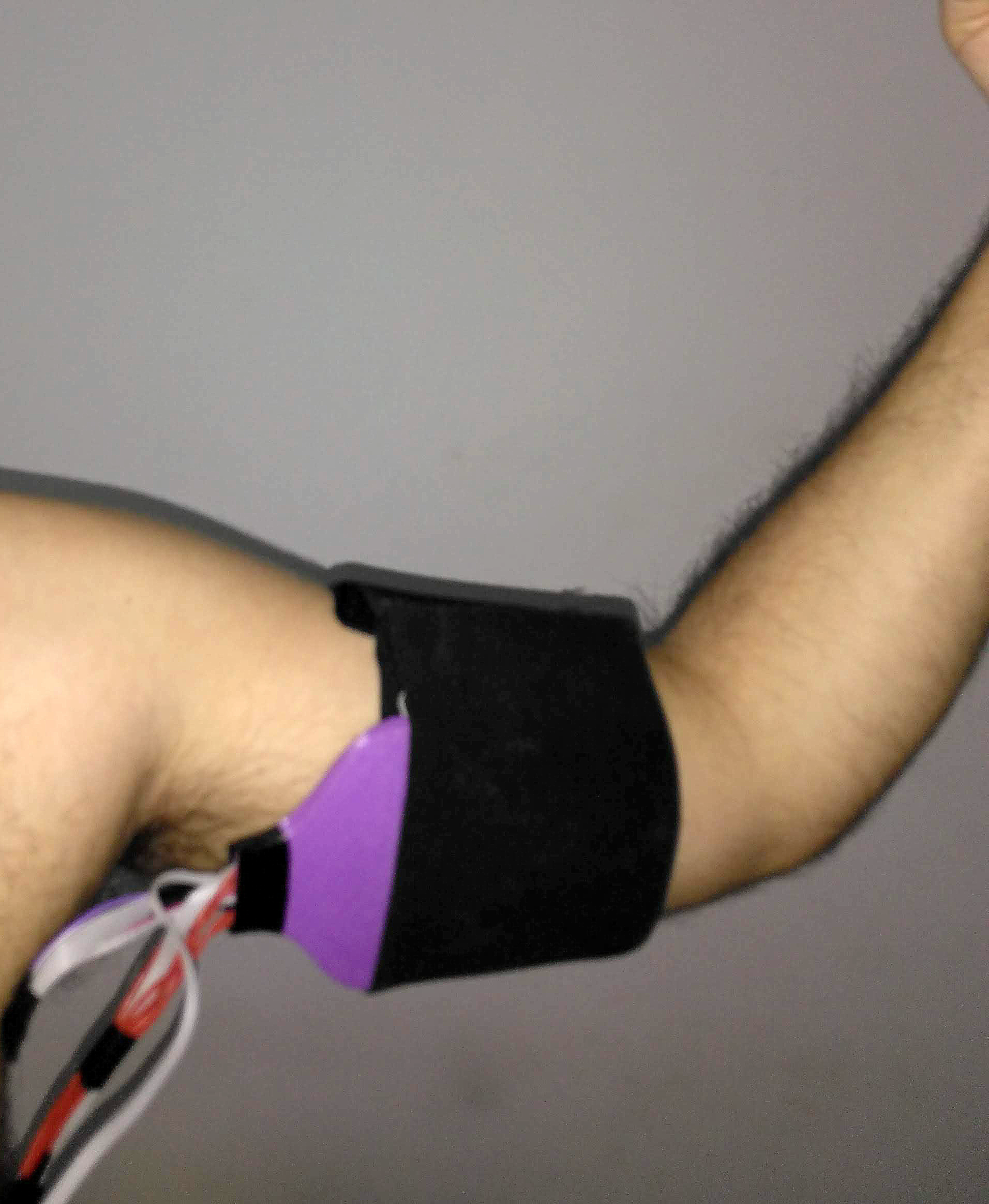
The touch stimulation interface can be worn in any part of the body, and in the figure below we show the interface being worn in the arm.
![]()
-
Testing the touch sensor
08/27/2018 at 03:57 • 0 commentsAfter programming the arduino of the touch sensor and making it transmitting the touch information to the computer, I designed a Python script for plotting the touch (file available)
In this stage, I plotted the touch as a image that updates in realtime as changes in the touch are detected. The force applied during the touch is represented by a reddening of the pixel representing the place where was touched.
In the next stages, we will use the information of the touch to control the stimulation interface and to control other stuff.
See the video below!
-
Hardware for touch and force detection
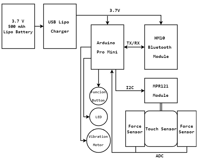
08/27/2018 at 03:50 • 0 commentsThe hardware for measuring the touch sensor and for communicating with the computer and the stimulation interface of the TouchYou needed to meet some requirements, for example being portable and having wireless communication. For reading the touch sensor, I used a breakout board with the MPR121 capacitive touch sensor controller. This module features twelve electrodes detection, configurable I2C address, a filtering system with debounce, and proximity detection and auto-calibration. The interface with the touch controller was made by using an Arduino Pro Mini board, with was connected with a HM10 Bluetooth module for the wireless communication. We also included a 3.7V Lipo Battery and a USB Lipo charger module, for hardware portability. A button for selecting the function mode, a LED and a vibration motor were also included for visual and tactile response for the hardware functioning.
![]()
In addition of measuring the position where the touch occurred, we also measure the pressure (or the force) of the touch. For the pressure sensing function, we chosen to use two force-sensitive resistors (FSR) attached to the surface underneath the touch sensor.
![]()
-
Building the flexible touch sensor
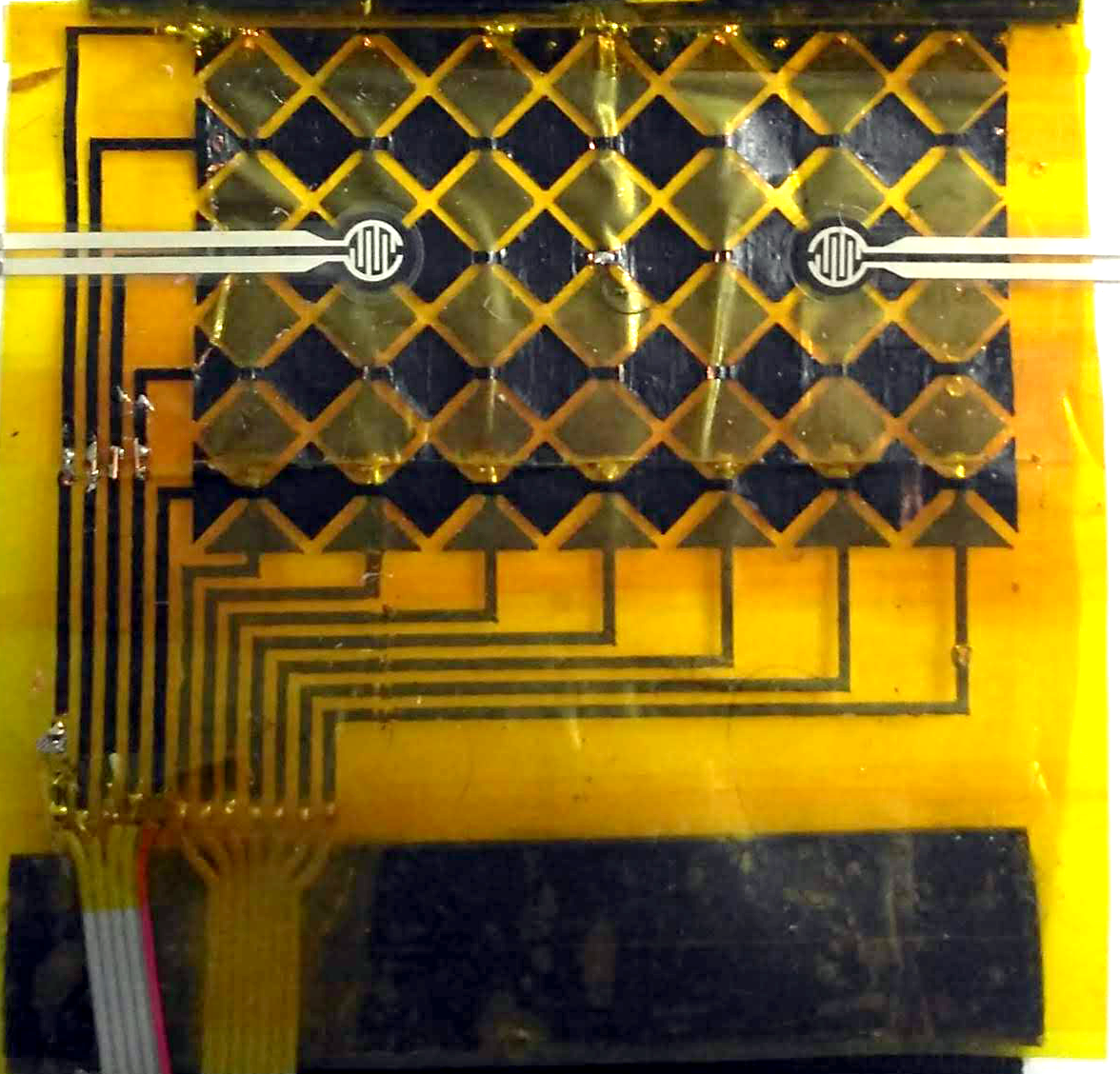
08/27/2018 at 03:46 • 0 commentsIn this build log, I would like to show how I built the touch sensor using the thermal transfer method.
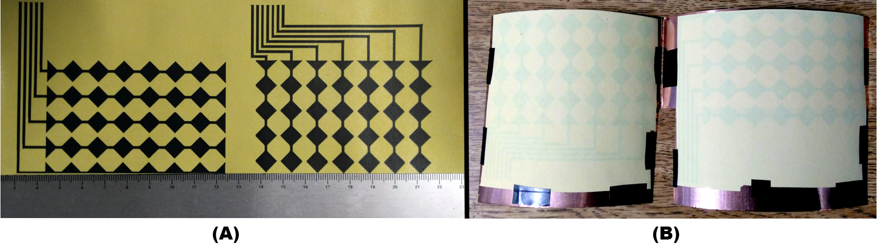
The method for creating the flexible touch sensor was similar to the one for PCB, but instead of using a copper board, we used a copper foil tape and a polyamide tape as a substrate. I have chosen the polyamide tape because of its relatively low cost and its insulating and high temperature stability characteristics. I printed the pattern for the lines and columns separately in the heat toner transfer paper, (A) and then we fixed each pattern over the copper foil tape (B).
![]()
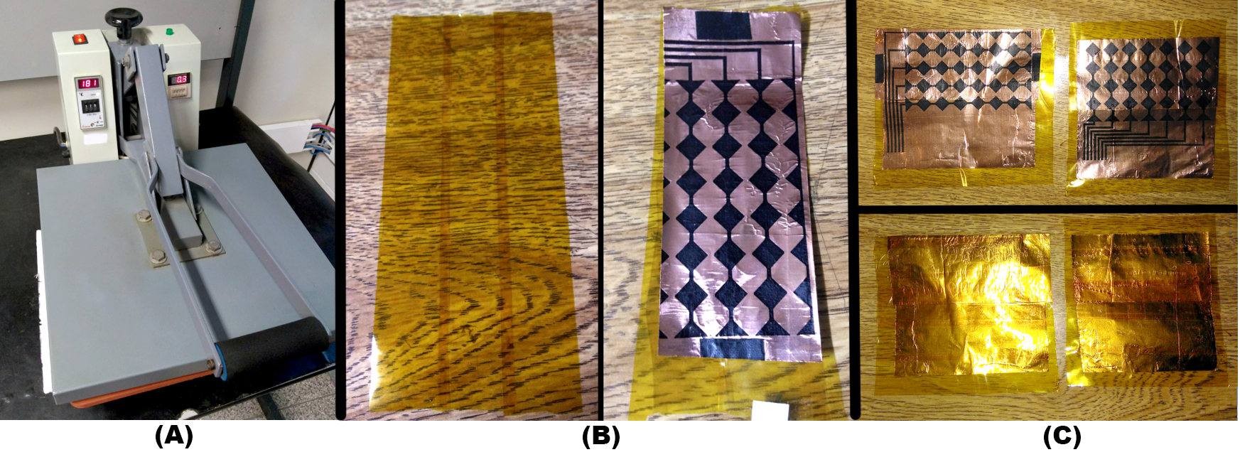
The copper foil tape with the printed paper was then placed on the surface of a heat press printer machine (A), which could be substituted by a clothes iron. The advantage of using the machine is to control the pressure applied to the hot surface, the temperature and the time of the process. In our method, we used 180°C and 70 seconds, which was enough for transferring the pattern from the paper to the cop-per tape. As the width of our polyamide and copper tape width were smaller than the sensor dimensions, we needed to join the strips for creating the substrate and the full sensor pattern (B and C). The copper tape was then glued on the polyamide tape.
![]()
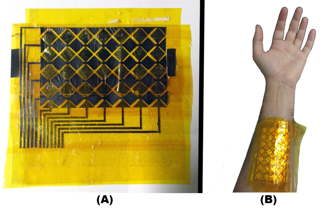
The last step of making the flexible touch sensor was to etch the copper in a similar way that is done for the PCBs. We dipped the copper and the substrate in a solution of ferric chloride, responsible for corroding and removing unwanted copper, leaving only the pattern of lines and columns of electrodes and its contacts. The two layers (lines and columns) were then cleaned, dried and glued one on the top of the other, creating the matrix pattern (A). The sensor was flexible enough so it could be placed around the wrist, meeting the initial requirement of designing a wearable touch interface ( B).
![]()
TouchYou: a wearable touch sensor and stimulator
TouchYou, is a pair of wearable interfaces that enables affective touch interactions with people at long distance.