 Xasin
Xasin-
1Solder things up!
The first step to any good hardware project like this is to take some time (i.e. a whole afternoon <.<) and solder up your first batch of sets.
For this, you will need:
- A package from Aisler, found here: https://aisler.net/p/QLILZEMV
- A couple of standard value 0805 Caps (47uF, 10uF, 1uF and 100nF, though you can use what you have)
- And a few 0805 resistors (10k, lots of 220R, 100k and 200k)
Oh, yeah, and buy some solder paste, because this PCB is best made with hot air reflow due to QFN components on the backside!
All ready?
Great, then head over to the GitHub wiki page for the more detailed, up-to-date instructions! -
2Print and assemble the casing!
Any good piece of hardware needs an appealing and sturdy casing to work right, doesn't it?
That's the same for this project, and we got you covered with an easily 3D printable frame!The model provided in the files consists of multiple parts. Model pieces named "COREx" are what you will definitely need to print - these are:
- The central core that holds speaker, PCB, battery, LED, and so forth
- The two side panel pieces that will cover the PCB.
If you have a multi-material printer, or know how to use Prusa's Single Extruder Multi Material feature with manual filament swaps, there are a few extra models to let you add some style to the casings. The appropriate model pieces will be named "COREx_MODa.b", with "a" being the material number and b just an identifier.
I recommend a clear material for the pieces going below the side-cover slits, and a nice, bright, contrasting material for the top indicators to add some "pop"!When the central holder is printed you can already start assembling it:
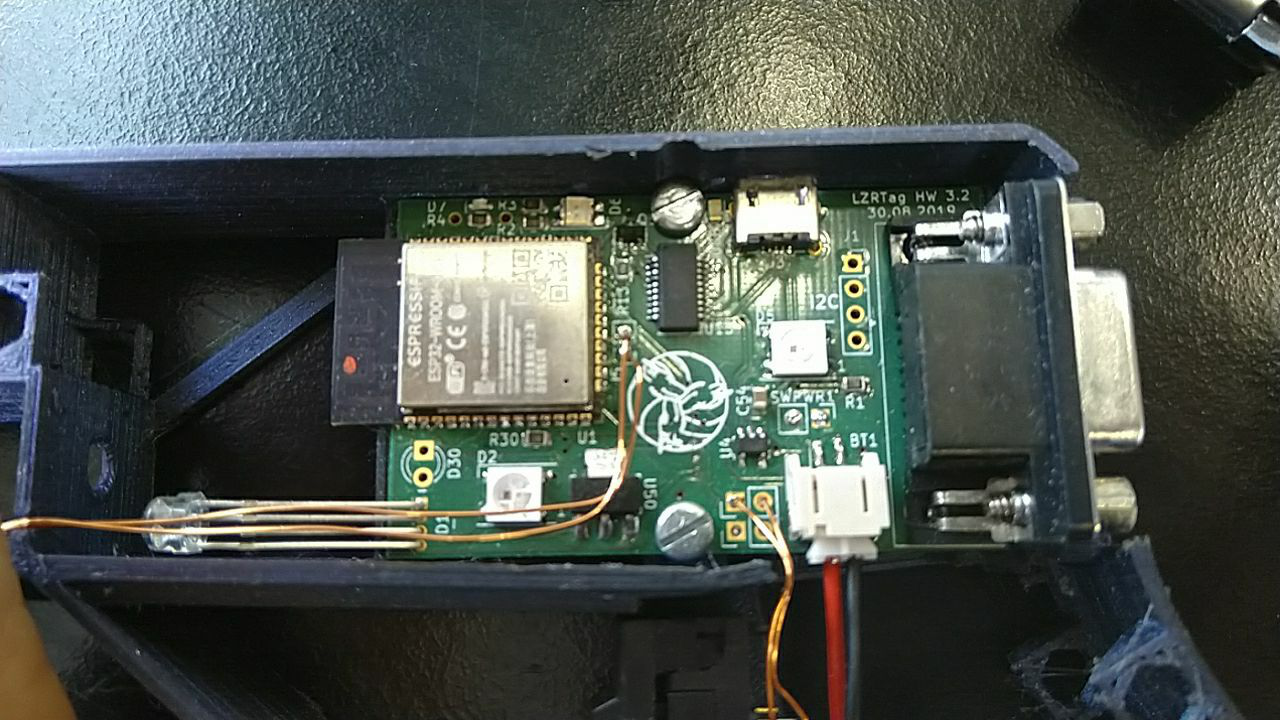
- Carefully insert the PCB. The navigation switch has to slide through the hole for it, so you need to angle the PCB a little and push the nav switch in. Then, just push the PCB into the frame and position it until the screw holes line up with the screw mounts on the printed piece.
- Screw the PCB in place with two M3 nuts and short (6mm) M3 screws. It should look a little like this:
Prepare the speaker, button and switch. We'll glue them in in the next step which will make their solder points hard to reach, so we need to add some wire now. The button needs a bit of wire going from its upper left and bottom right pins to the two upper connection points next to the JST connector.
The speaker's wires need to reach from the front nozzle section of the casing to the two connection points next to the ESP32 - or, if you use a breakout board for the I2S audio, to that.
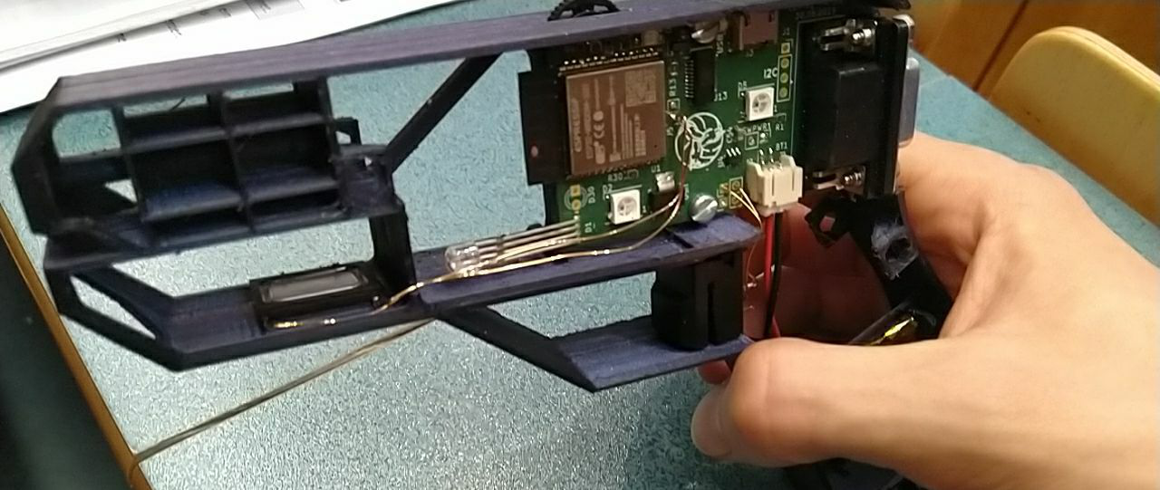
The power switch needs its wires to reach from the little cutout below the D-SUB connector to the two connection points above the battery JST connector.Glue in the different components!
You can use either a strong adhesive tape or something like loctite or cyanacrylate. Important is just that it can solidly connect the different parts to the frame, but that it also doesn't seep into the mechanics of the button and switch.
For the switch and speaker you won't need that much glue, since neither will experience that much force - but for the trigger button I highly recommend a little more, just because players will probably be tempted to smash it a little harder than they need to.Push in the two front LEDs (3mm IR LED and the WS2812) into their respective spots in the casing. You shouldn't need glue to fixate them since the case should fit them snugly, but it can't hurt to add a bit to make sure their bond lasts.
Once they are in place, you can solder them up, using some copper wire to hook them to the six connection on the front of the PCB.
You shouldn't have to cross any wires over one another, but I highly recommend double-checking the polarity of the WS2812 and the IR diode!Slide in the battery into the holder. Depending on the type of battery you get,
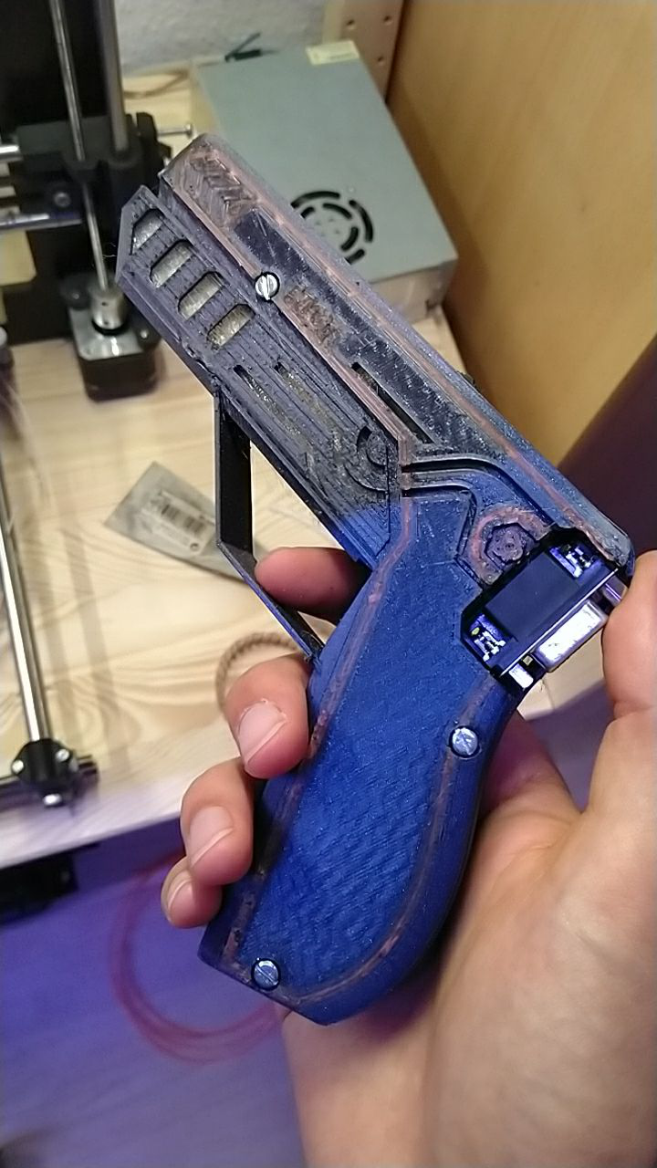
Push M3 nuts into the six attachment points on the top and bottom of the core casing. You can fixate them by heating them up so the plastic melts around them, or just by adding a little more glue. Either way, make sure they sit flush with the surface of the casing
Screw on the top and bottom halves using the same small M3 screws as for the PCB!
If everything went well, your piece should look somewhat like this now:And now?
Plug the PCB into your computer via USB. If the firmware is already loaded it should start charging the battery (indicated by a very slowly growing battery LED). If not, you can go to the next step to flash the firmware of the ESP and configure your access point
LZRTag - Flexible DIY Lasertag
An easy to build, program, modify and use AVR and ESP based Lasertag system for everyone!
Discussions
Become a Hackaday.io Member
Create an account to leave a comment. Already have an account? Log In.