 Jan Bert
-
1Mechanical build
Warning: if you want to build your own VSTiBox, please consider that the v1.0 design files contain some errors, but a manual workaround is possible. During the build process of my VSTiBox I came across a number of design mistakes which I have tried to document as much as possible in the project logs and build logs. The PCB versions which I have built are all v1.0. For the mixer and the control PCB's I have fixed these errors in the v1.1 schematics, but I have not finished routing the v1.1 PCB's yet. The mechanical design files also contain a few problems which I will describe in this build log.
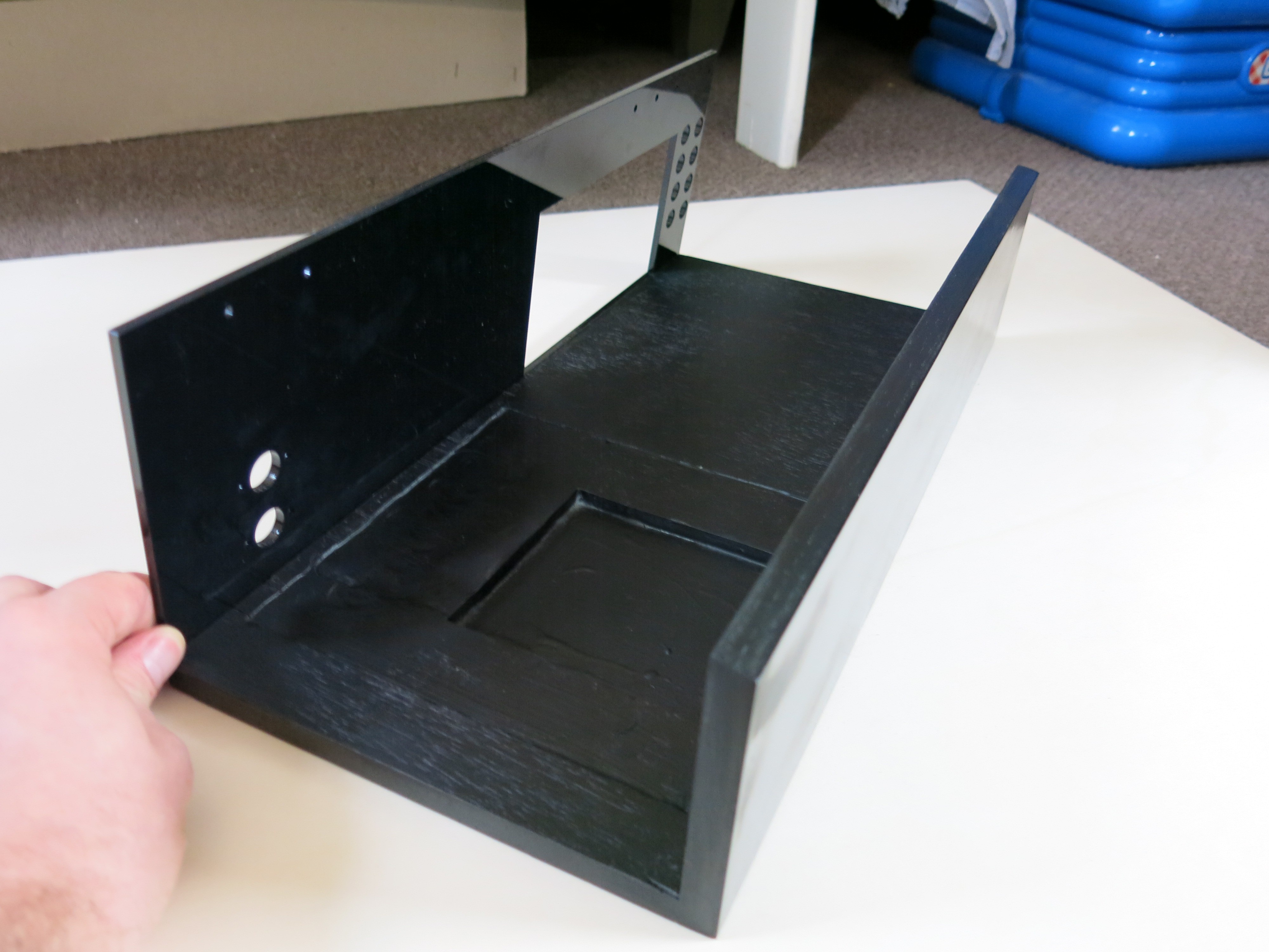
The base of the VSTiBox are two 14mm multiplex plates. The dimensions for the two plates are 420x188mm and 420x102mm. I got the plates from my local hardware store, sawed to my specifications. The 102mm front plate needs to be sanded off, at the same angle as the top plate and mixer PCB. The plates are mounted together by 7 screws, evenly spaced. Fix the plates at an angle of 90 degrees, and align their sides. Use a hand drill to drill holes for the screws. Use a countersink drill bit to let the head of the screw fall within the front plate.
![]()
The micro-ATX with the CPU cooler mounted do not fit correctly in the case. The entire space beneath the motherboard needs about 3 more millimeters, and the space beneath the cooler needs to be dremeled out to a depth of about 9mm. After the two multiplex plates are screwed together, I used wood filler and sandpaper to get a flat surface. After a layer of base paint it can be painted with black spray paint.
The acrylic parts can be ordered online. All the drawings I used for ordering are in https://github.com/janbert/VSTiBox/tree/master/cad/lasercut
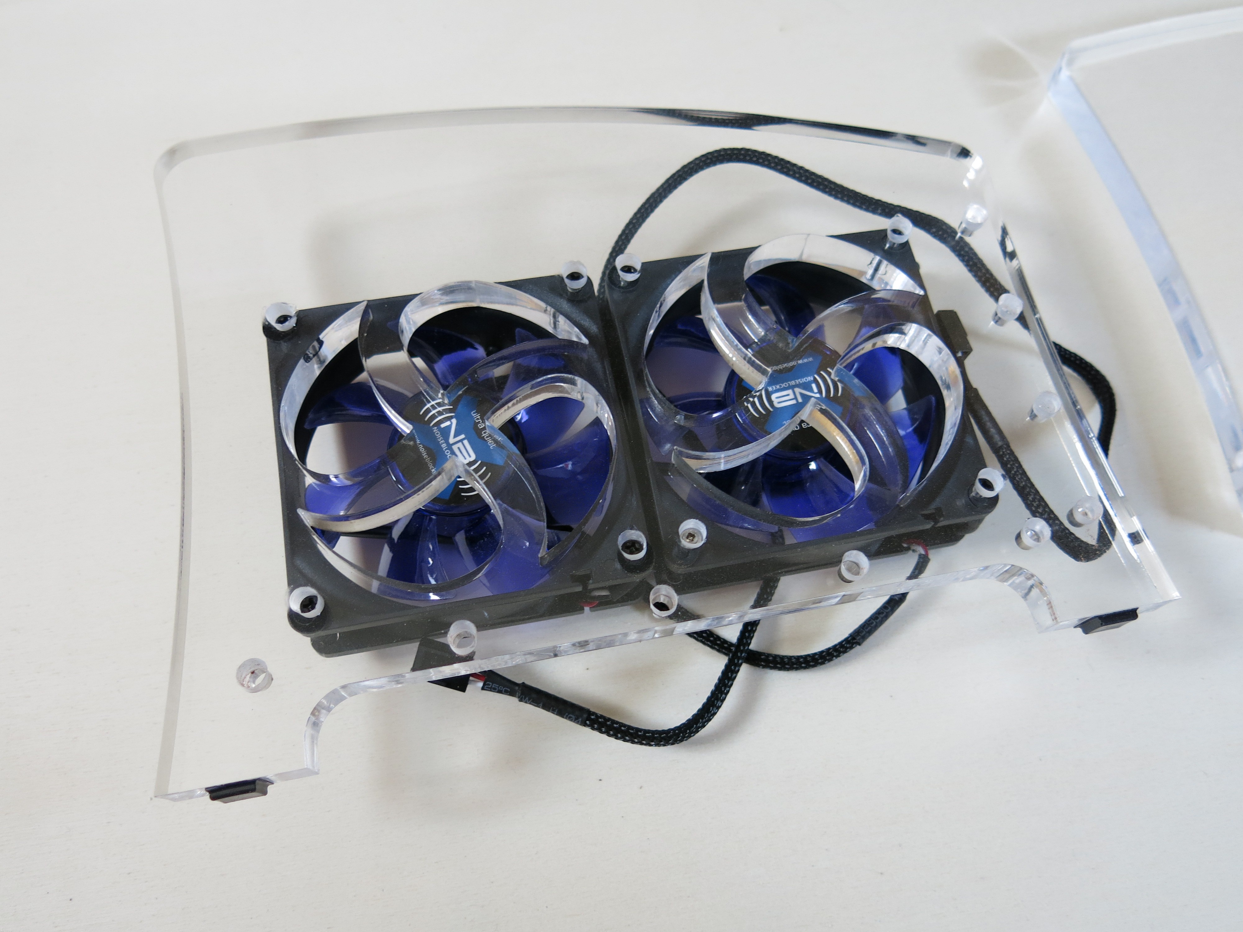
I use 3 different sizes: 1/16", 3/16" and 1/2" inch. The square cut-outs for the silicon buttons in the black and clear top panels need at least an additional 1mm clearance. This can be done manually, but it is better to update the design files. The acrylic sidepanels have a 4mm pilot hole. They need a counterbore to fit the screws - i think I used 10mm. Use the lasercut pilot holes to mark the drill positions on the multiplex plates. With the counterbore the screwhead sits at about 4mm from the back of the plate. The fans can be mounted on the acrylic side panel with the same counterbore screw holes.
![]()
The ATX PSU is glued in place by epoxy. The back and topside acrylic plates have drill holes for screws in a small piece of metal profile. Though I started making this profile, I have not finished them yet; the topside screws have never been mounted. In front of the PSU there is place for two SSD's and the linear PSU.
![]()
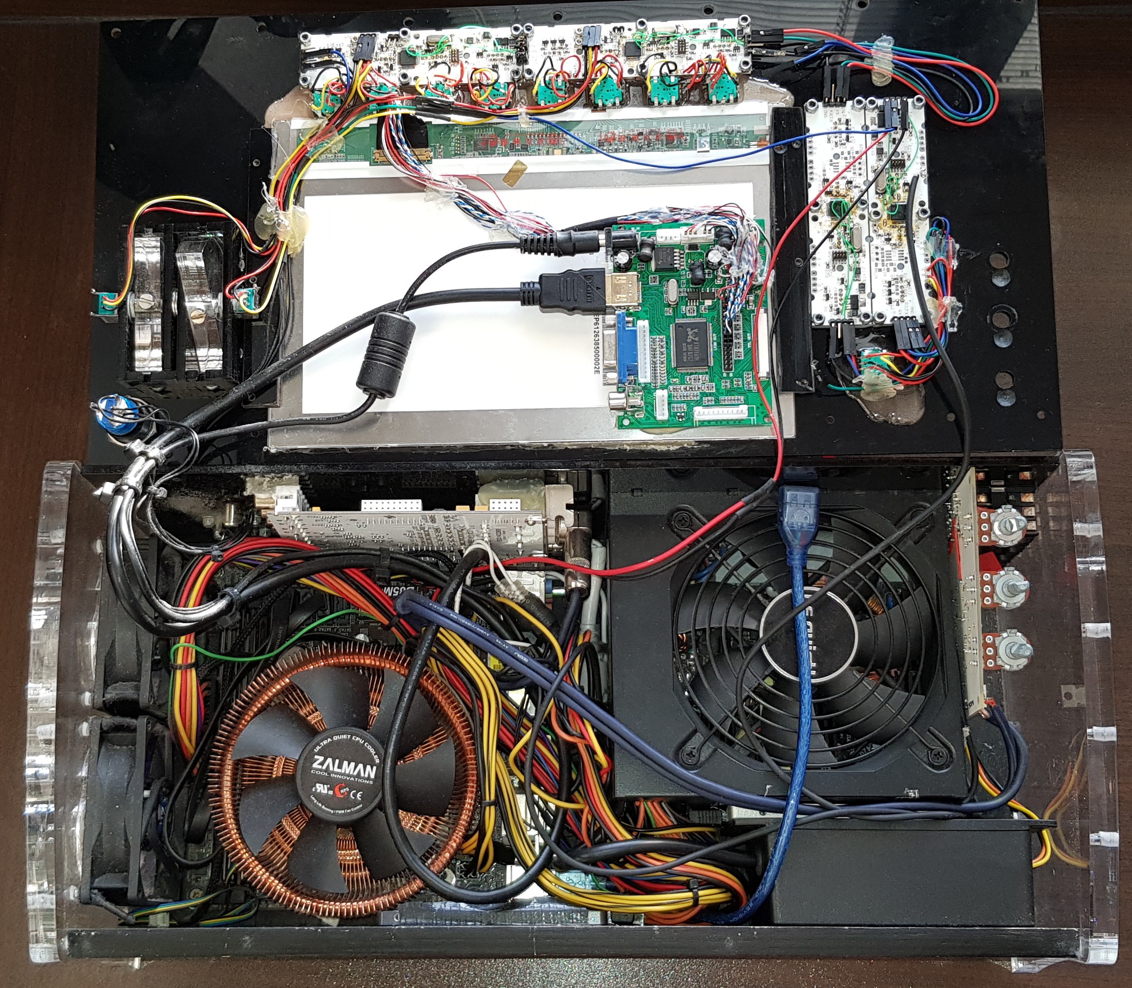
The wiring is a bit off a mess, I know. This is something I did not plan in advance and just went with it. The white Juli@ audio interface above the CPU cooler is glued in place. This is not ideal and a neatly designed screw connection would be much better. The display is mounted by two scrap pieces of black acrylic. I later decided to fix it with silicone sealant. The display is a 10.1 inch TFT display from ebay. I thought is was a full HD display, but it turned out it was a 1280x800 display and I misread the ebay item details. It uses a 'HDMI+VGA+2AV Driver Board' which is glued in place with some epoxy. The power comes directly from on of the 12V lines from the ATX PSU. This somewhat problematic; sometimes the display does not start correctly which I think has something to do with the timing of the 12V power and the HDMI signal from the motherboard. The problem only occurs after it has not been used for a long time. A simple solution is to restart the computer. The display always functions normally after the second boot.
-
2Controller hardware
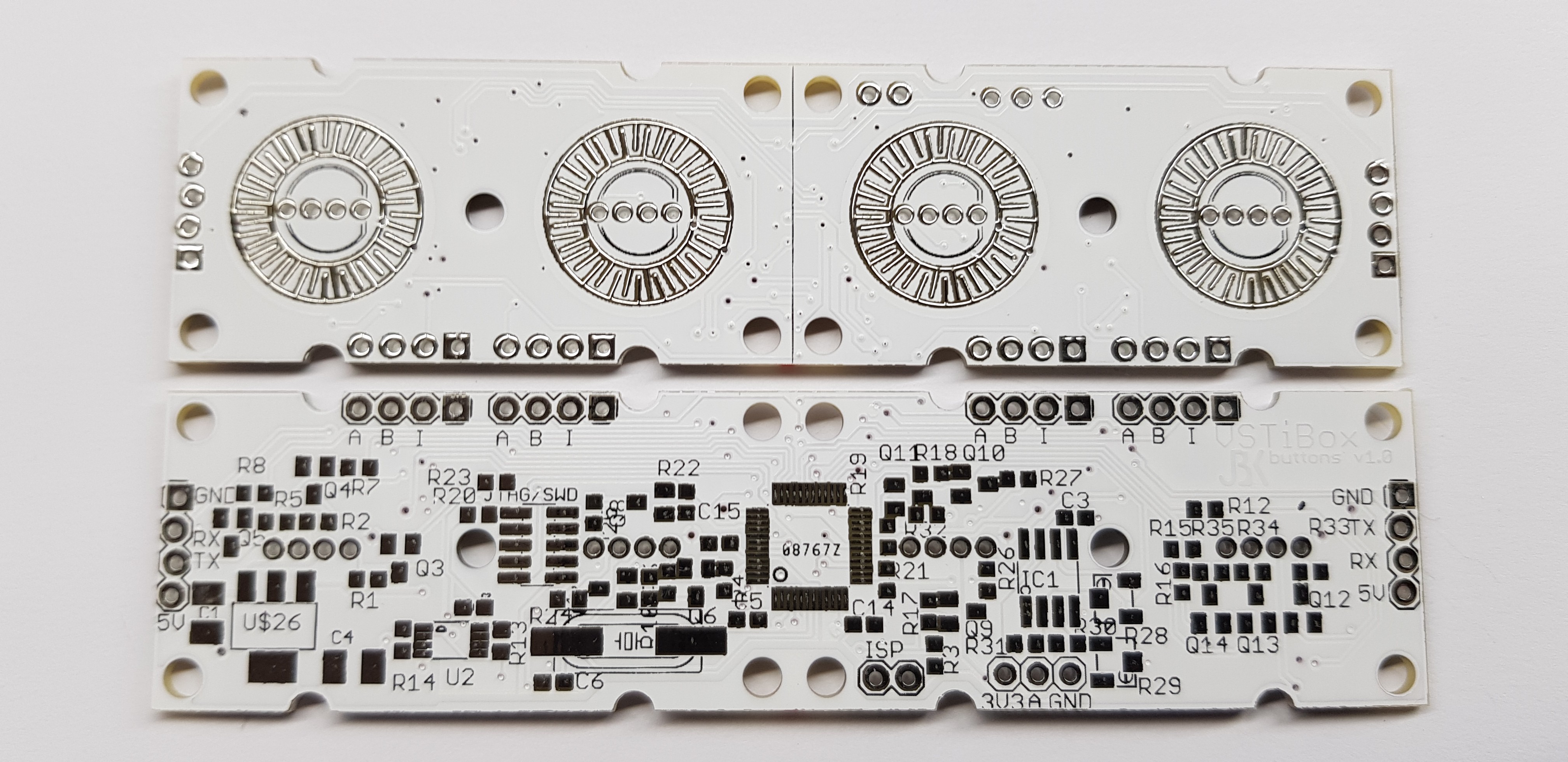
The controller PCB's contain a lot of SMD components, but soldering by hand is do-able. It is best to start with the hardest part: the LPC1114. I use a technique to solder all the pins with a thick layer of tin. Then I hold the PCB at an angle of about 30 degrees, and let all the tin flow to my solder iron; away from the microcontroller. Use old fashioned leaded tin which is much easier to solder. You can also add some flux to make this easier.
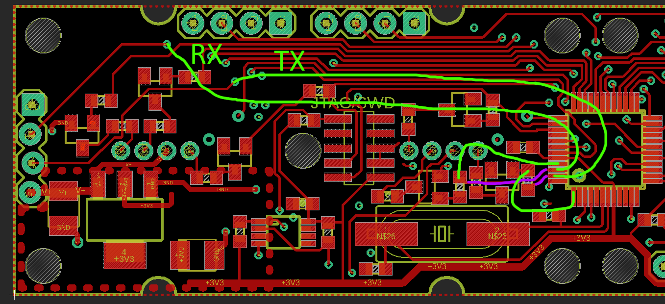
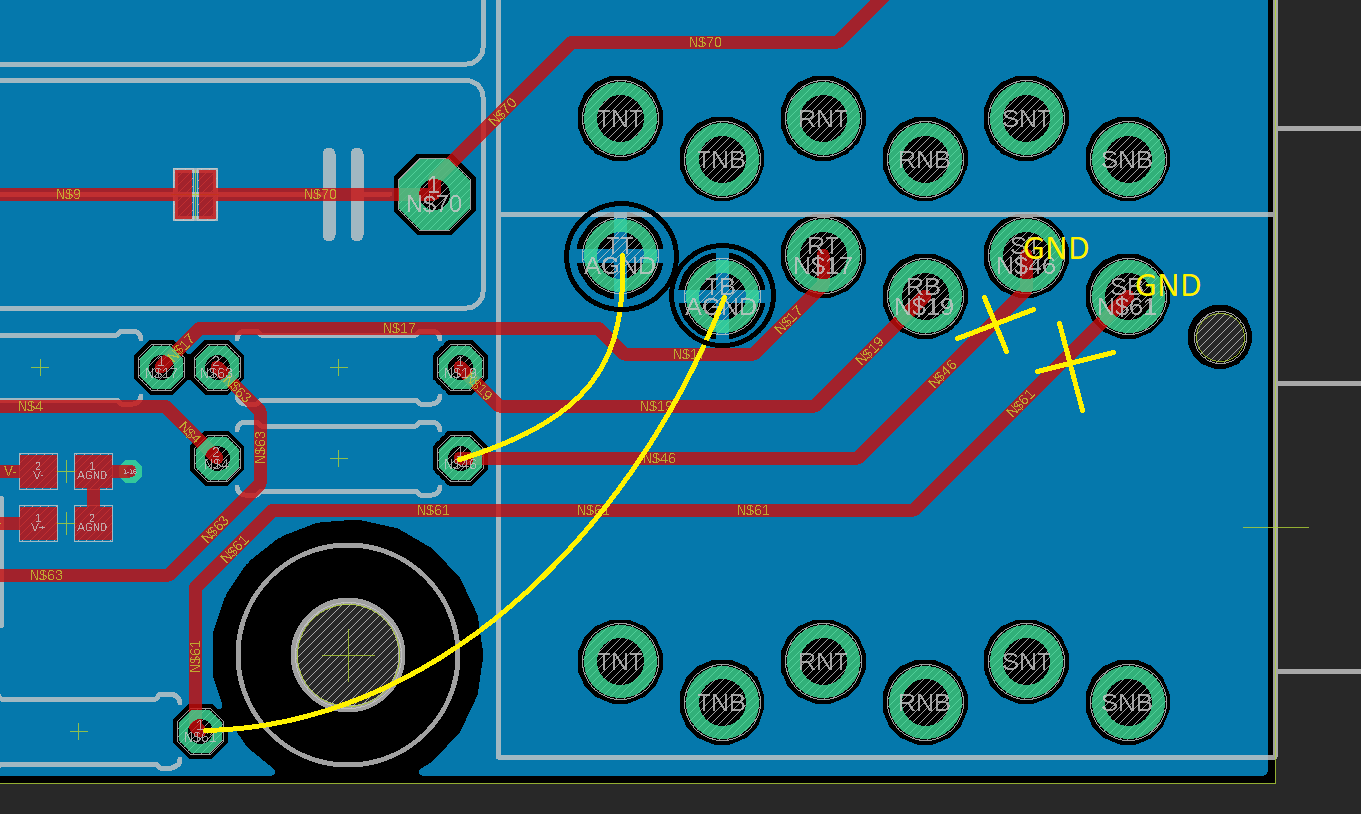
As described in the blogpost about the controller, I forgot to route the UART TX and RX to the LPC1114. The following image shows the green wires that have to be added manually to get it to work. The purple traces are not used anymore. The either have to be cut, or R4 and R10 have to be mounted in a vertical position on only one solder pad. The wire can then be connected to the other end of the resistor. I added schematic v1.1 that contains the fix to the GIT repository, but did not finish the routing. The ground planes are very thin at some points. A 4-layer board with a dedicated ground plane would be better.
![]()
The final connection to the PC is a USB serial device (like an FT232RL) with 3V3 TTL uart. In this way the VSTiBox host software can iterate over the available COM ports on the PC and automatically connect to the first controller.
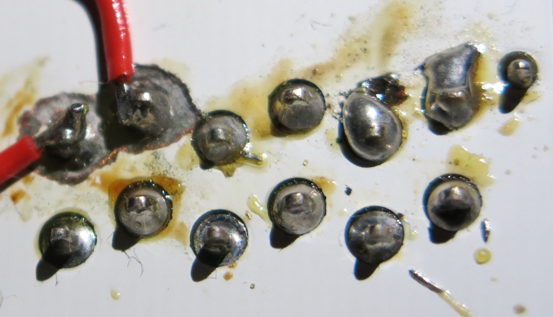
The biggest mistake I made with the controller and which cannot be fixed, is ordering a default PCB without gold finish. After a few years the pads for the silicon button will corrode and the contact gets worse with more jitter. My hardware is already suffering from this and I had to implement a pretty heavy debounce filter in software. A better choice would be to order the board with a gold finish, or even a graphene layer on the button contacts. The silicon buttons also have a conductive graphene ring.
![]()
-
3Controller software
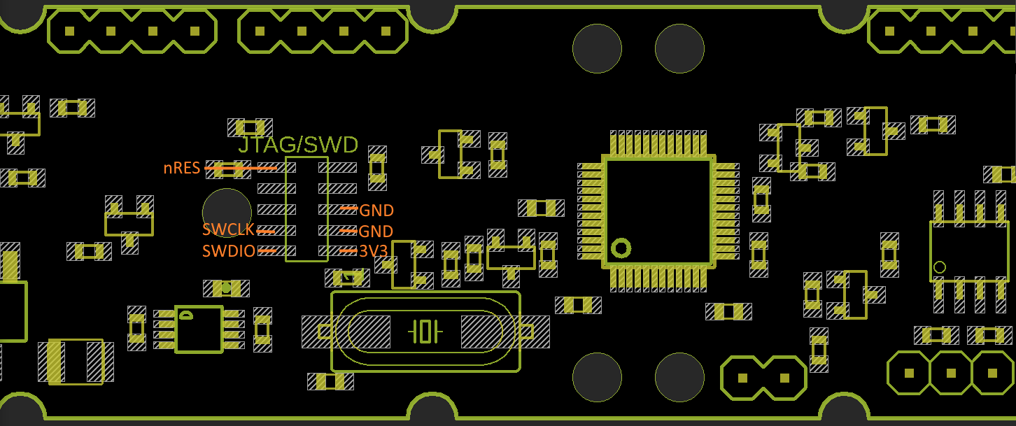
The c source in git/sw/control/src is build with Keil uVision. This IDE is free up to 32KB build size. The LPC1114 has exactly that amount of ROM so it can be fully used. A standard 10 pins 1.27mm SWD connector can be used to program it with a programmer like a JLINK or ULINK. I personally prefer the JLINK because it is very quick and has an API which can be accessed from .NET, but that's a different story. The following image shows the pinout of the SWD connector.
![]()
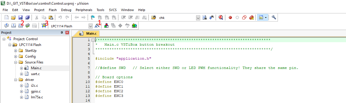
When Control.uvproj file is opened in Keil, you first have to check if there is a SWD connection. Go to (1) 'Options for Target' => tab debug => Settings for you selected debugger. Make sure SWJ is enabled and SW (SWD) is selected. Now you should be able to see the core ID. Hit rebuild (2) and Load (3).
![]()
If the target is progammed once, you can only connect to it the first 3 seconds after powerup, because the SWD pins are used for driving the leds. To enable SWD debugging (and disable the led) uncomment the #define SWD.
-
4Linear PSU
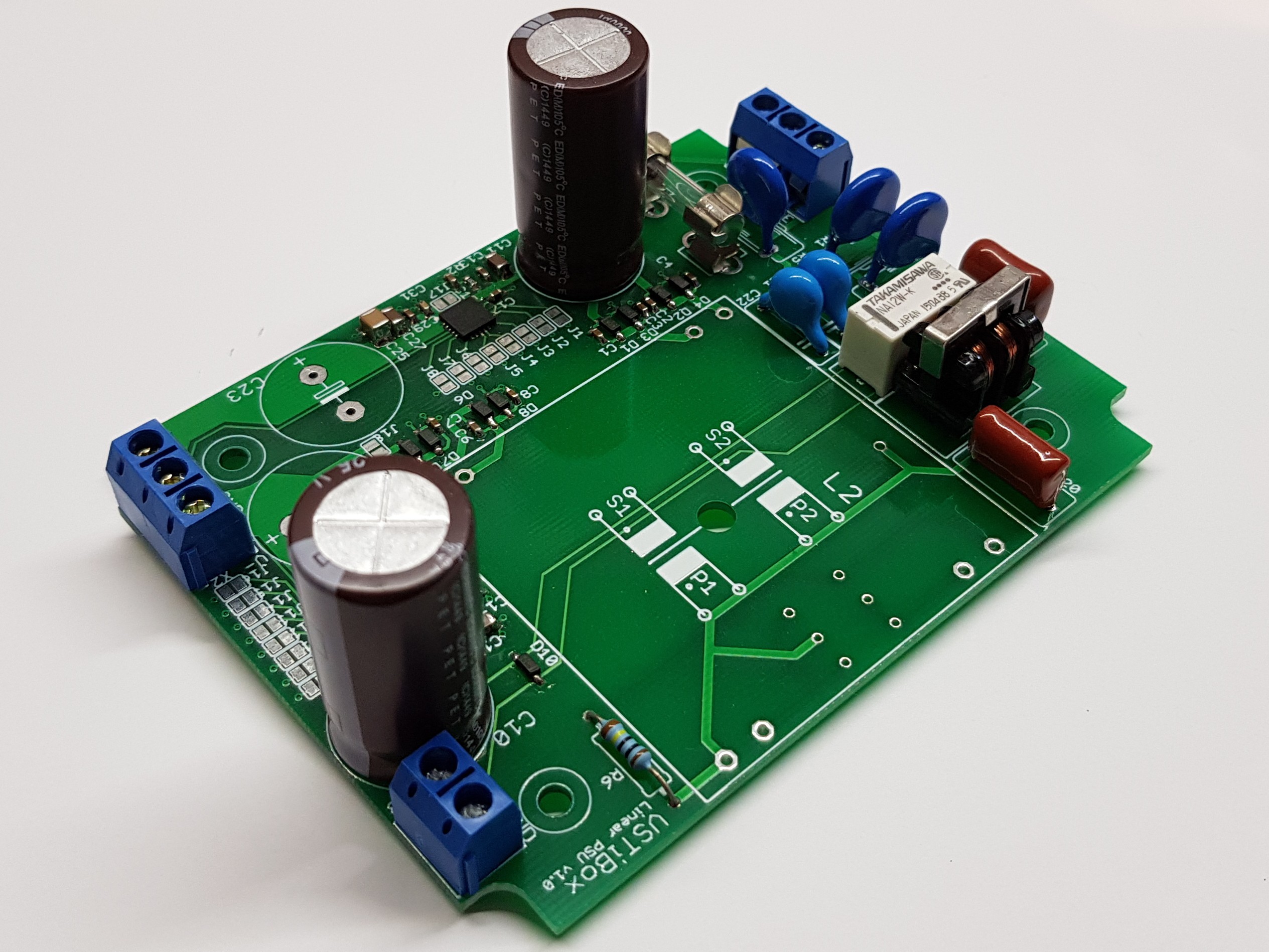
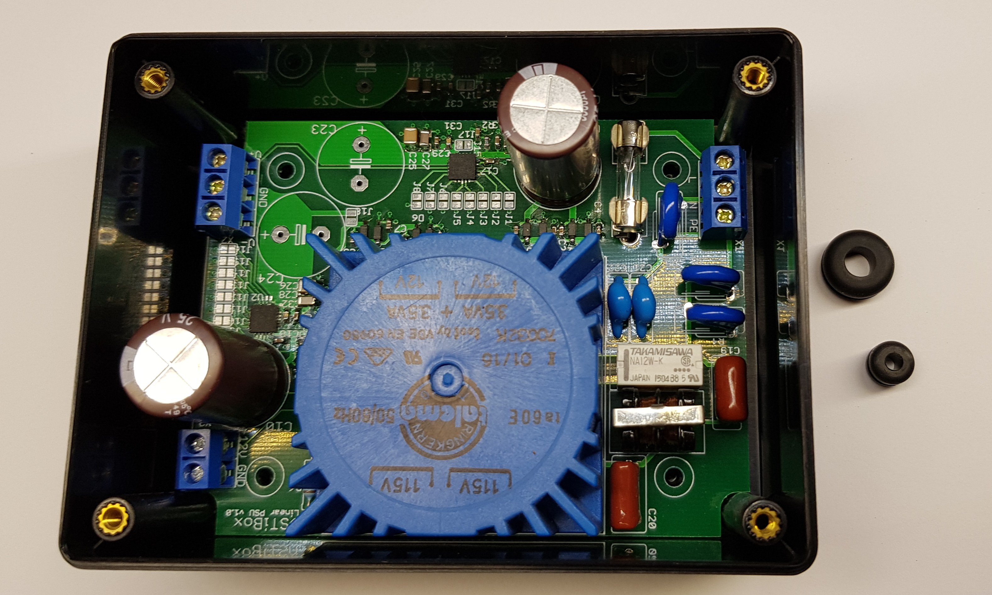
The linear PSU is build around two TPS7A4700 linear regulator IC's in a VQFN package. These can only be soldered using hot air from a SMD reflow station. I use a aoyue 968a which is very affordable unit. My advice is to start with these, then start with the smallest parts and end with the biggest ones.
![]()
The PCB fits perfectly in its enclosure and is mounted by screws. On the BOM are two grommets with different sizes. Drill a hole in the enclosure where the wires need to exit. The fit the grommets in the hole and mount the cables. Use one big grommet for 230Vac and two small grommets on the low-voltage side for the output power and the slave input.
![]()
-
5Wiring
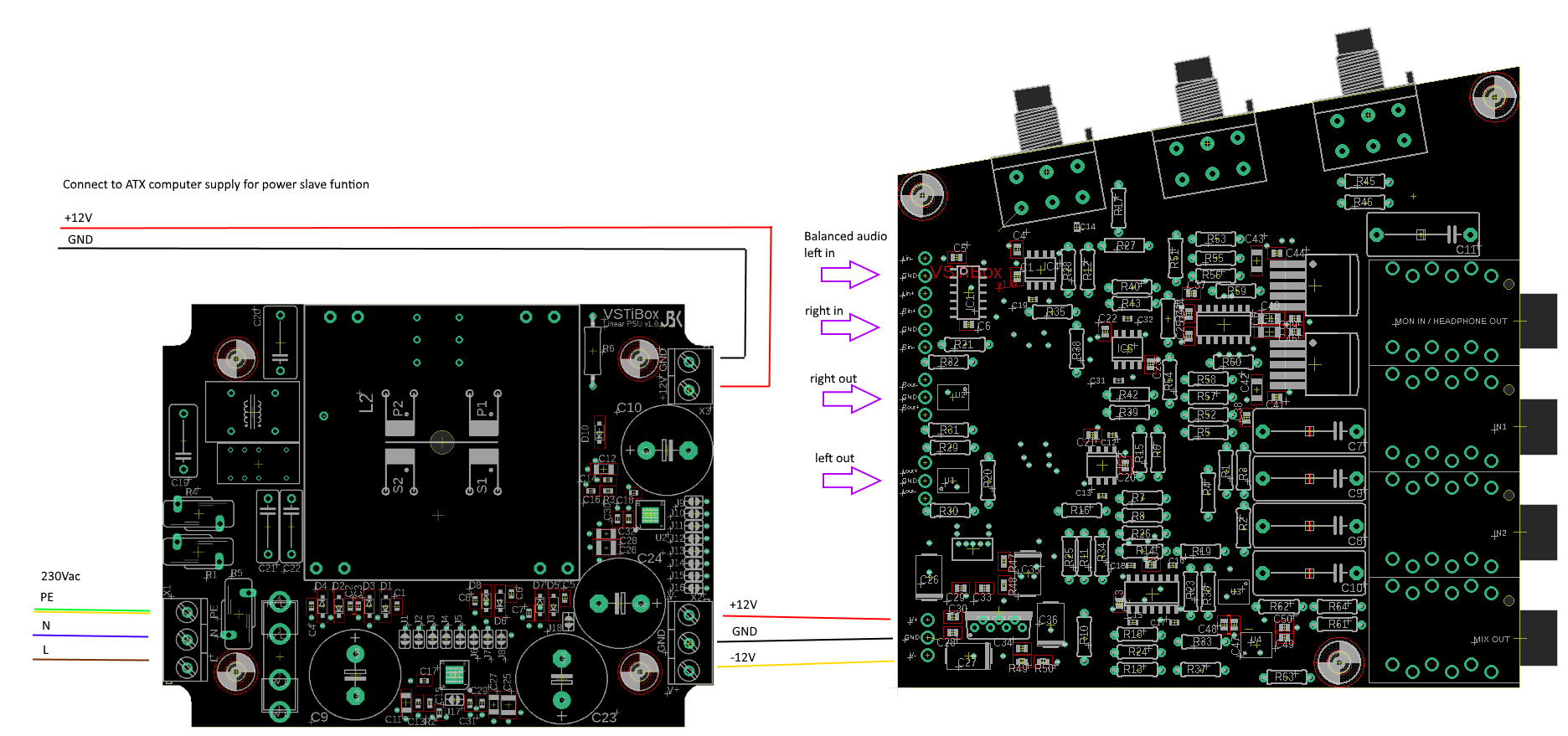
The following image shows the wiring of the audio, the mixer and the linear PSU:
![]()
In theory the audio in- and outputs can be directly connected to the soundcard. When I was using the VSTiBox on the audio input on a Yamaha P200 stage piano, I got a terrible noise which had to do with ground loops. This originated from the GND of the ATX computer supply. The only way I could quickly solve this was using isolation transformers. I used the Behringer HD 400 and took the PCB out of its enclosure because it was a bit to big. The I mounted it between the audio interface output and the mixer audio input. This is a far from ideal solution. The transformers are apparently not made for +4dB audio signal; I cannot put the audio interface at full volume. This is easily compensated by the volume control on the mixer, but it is not ideal. Also the transformers have some impact on the audio quality. When playing on stage this is hardly noticeable, because the synth sound is part of the mix and DI boxes are used everywhere that do exactly the same. But when playing on my balanced input studio monitors you can hear the difference. I can think of two solutions to fix this problem; use high-end Jensen transformers, or use an optically isolated audio on the computer audio interface. The ATX computer supply realy is the problem here.
-
6Mixer
The mixer is a two layer PCB with a mix between through hole and SMD components. Again it is best to start with the smallest components.
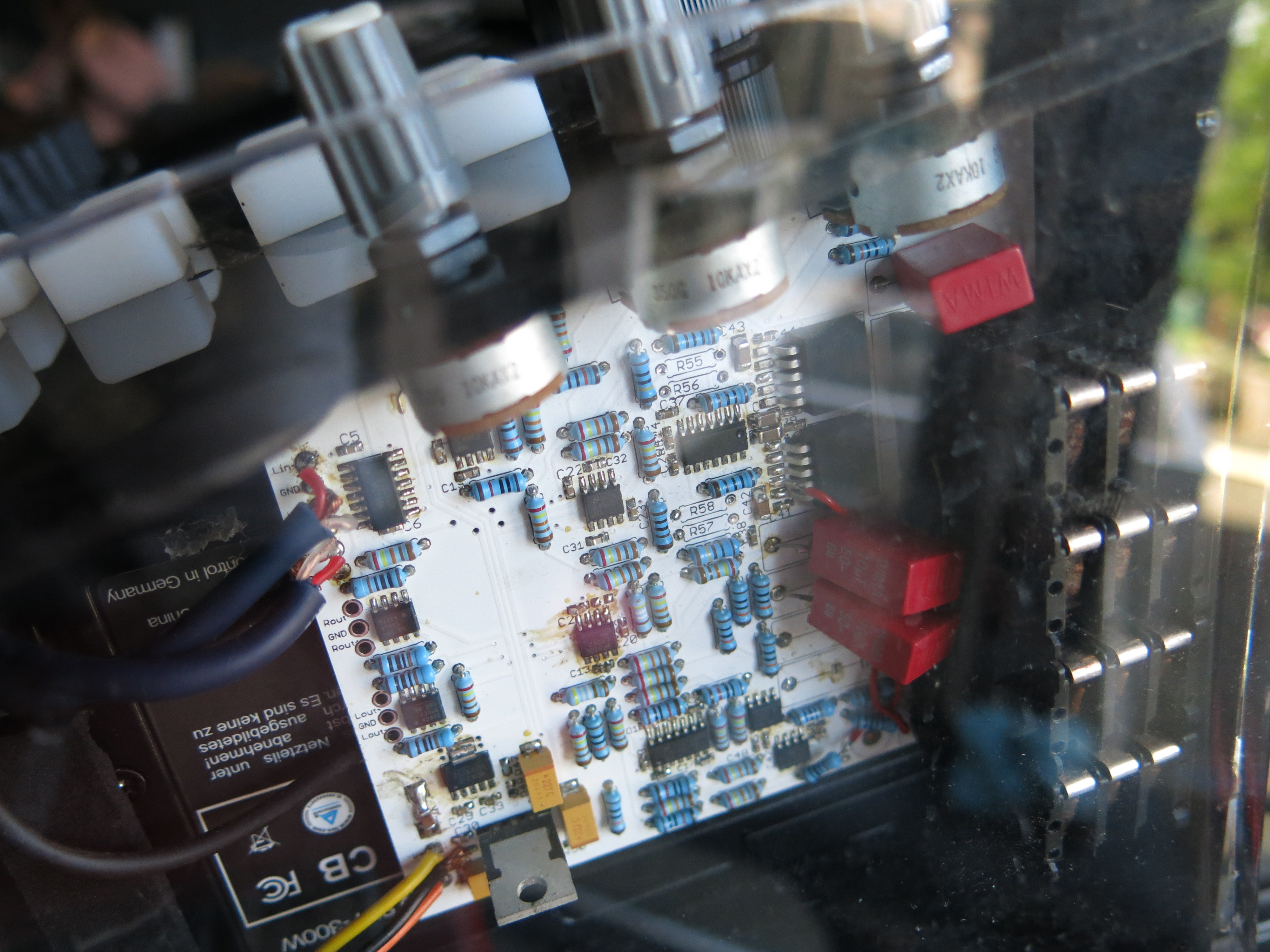
I made a mistake is in the servo circuit for the LME49600 headphone drivers. The solution is to simply leave the servo disconnected by not placing R55, R56, R57 and R58. You can see them being left out in this image:
![]()
The footprint of the capacitors is wrong. Because they have long leads this is not a big problem, although it doesn’t look pretty.
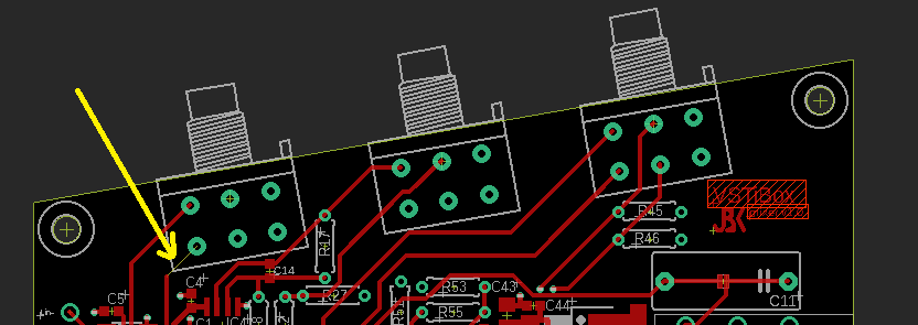
I must have missed a DRC check, because there is an unrouted line on the board as shown in the following picture. This is easily fixed with a small wire.
![]()
Another less easy to fix mistake is in the footprint of the Neutrik Jack connectors. The ground and signal pins are swapped. This has to be done for each of the four connectors.
![]()
The signal pins that are connected to ground have to be dremeled out, so a wire can be used to connect them to the resitors with the correct signal. The ground pins can easily be soldered to the ground plane by scratching away some of the solder mask. I really need a can of Isopropanol :)
![]()
-
7C# VST host
The VST host can be built with Visual Studio 2012 or 2017. I'm sure other versions will work too, but I have not tested that. First of all, make sure you have the 'develop' branch. It simply contains all the latest bugfixes. A while ago I decided to write part of the VSTi handling. I do think it works better now, but I did introduce some bugs that were already solved in the previous version. Most of them are already dealt with, but I should write down the known bug list in Github sometime. If you are unfamiliar with GIT, I would recommend looking into TurtoiseGit and GitKraken.
![]()
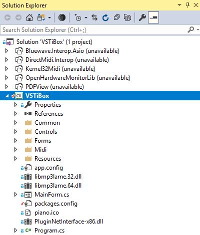
In contrast to majority of the opensource projects I have included the release build DLL’s from the other projects in the VSTiBox project. This is mainly because of DirectMidi.Interop which is kind of hard to build. You have to download an obsolete DirectX SDK. But DirectMidi won’t build against it directly. I took the lazy way and renamed one of the files in the SDK. Because this is an ugly solution I’m not recommending it and just present to you the release DLL that can be used without installing the SDK.The other reason is that the debug version VSTiBox can now run on the release version of Asio and VST.NET, which it absolutely needs for non-crackling audio. A third reason is that it makes searching easier. You do not get false hits from the other opened projects. Therefore you can simply unload all the projects except the VSTiBox.
Please keep in mind that the software is written for exactly my screen resolution and it does not scale to higher resolutions. When the VSTiBoard will be equipped with a 1920x1200 screen, I will have to do some modifications to all the custom controls.
To auto start the VSTiBox host software when Windows starts, it is nice to start with a black screen. Clear the desktop from all icons, and set a solid black background. Set the task-bar to auto-hide. A shortcut to the release executable in the Release build folder must be added to:
C:\Users\<user name>\AppData\Roaming\Microsoft\Windows\Start Menu\Programs\Startup
Also you could change the Windows boot logo, but I didn’t try this personally.
-
8VST host settings
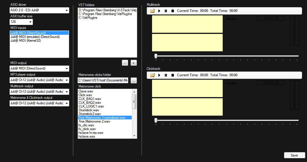
On the first run the audio and folder settings must be selected. You can access the settings window from the right bottom menu scroll-list. Select your ASIO driver and buffer size. I am running at 128, but would like to optimize the audio processing a bit further so I can run on 64. In the early days of the VSTiBox I used to run on a buffer size of 64, but with all the midi handling and other features added I cannot always run crackle free on this anymore so I have to pick 128 which is still a good for a low latency. Multiple MIDI inputs can be selected by multiple lines in the listbox. The player for the recordings (MP3 player) , the multitrack and clicktrack/metronome players can all be separately selected. They do not work with ASIO. I want to fix this in my next generation VSTiBoard which should have a multichannel ASIO interface. Currently I do not have that, and can only use the onboard audio and a separate USB audio interface.
![]()
VST folders can be added by the + button. These folders are scanned at startup. I used to have some problems with VST that do not support a data chunk for saving and loading its VST specific settings like the active program and the filter settings. Therefore a message will popup if a new VST is found that does not support this. However this problem is probably solved now in a bugfix commit that happened right before I migrated to Github. The metronome click can be selected which will be played when the bottom right RGB button is pressed.
The multitrack and clicktrack actually do no belong on this window because they are bank-specific. I'm going to move them to a dedicated window.
-
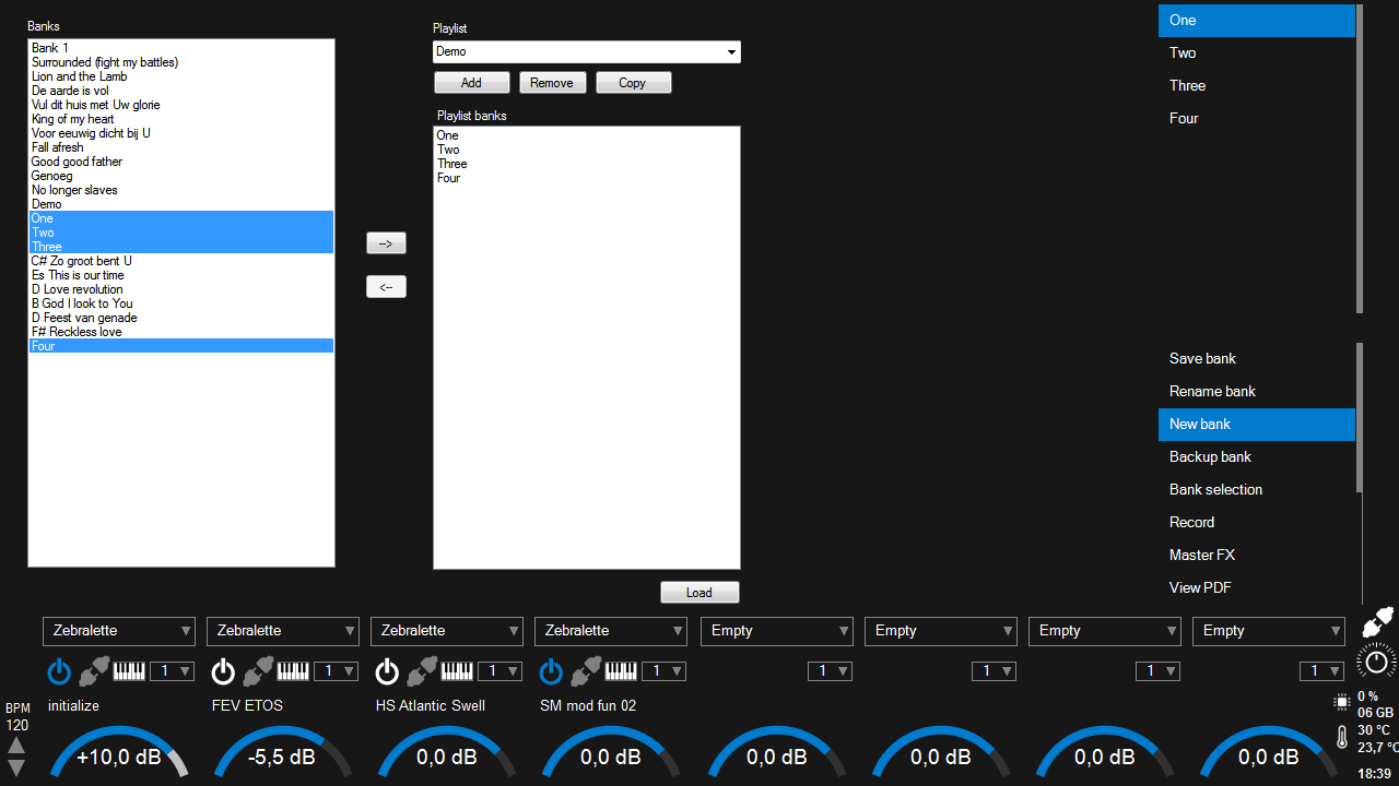
9VST host bank editor
The UI of the bank editor is in a kind of quickly-hacked-together state, but it is fully operational. The main scroll-list controls and the VSTi channel strip are fully designed in the Elysium style, but for the other windows I did not put the effort in yet. So all the controls you see are default toolbox controls with the typical Windows look&feel.
The folder My Documents/VSTiBox2 is created on the first run of the VST host software. The 'Banks' in the left column is a list of bank XML files in the VSTiBox2 folder. There is also a settings file which contains a list of banks, and all the other non-bank specific settings. In the right column a playlist (setlist) can be added, deleted or copied from an existing playlist. The column below that shows the banks that are currently in the playlist. They can be re-ordered by drag- and dropping them. The upper right scroll-list does not support this, so re-ordering has to take place in the bank editor. To add or remove a selection of banks to the playlist, use the buttons with the left and right arrows. Use 'Load' to load the playlist. The last loaded playlist is always automatically loaded at startup.
![]()
My bank list used to be a lot longer. But when I changed to the v2.0 which is currently on Github, I did break compatibility with earlier saved banks. When I need a previously saved bank I simply convert it by hand to the new XML format.
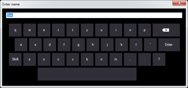
The lower right menu can be used to save, rename, or add a new bank. The new bank will then be added to the currently active playlist. A touch keyboard will pop-up to enter the new bankname. In this way it is easier to operate by mouse or touchscreen only without needing a keyboard. I couldn't find a simple and clean C# control for this so I built one myself:
![]()
-
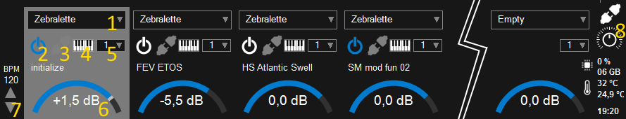
10VST host channels & functions
In the following image I have cut out VSTi channel 4 to 7. Besides toggling the VSTi channel on and off, the editor window of a VSTi is loaded when a silicon RGB button is hit. Lets call this the channel button. The channel for which the VST editor is visible is highlighted. To focus on the VST editor of another channel, the channel button must be pressed once to load its UI, and a second time to enable it again, because pressing it will toggle the VSTi on and off.
![]()
- VSTi selection; select one off the VST's in the VST folders as defined in the settings window.
- Indicator which is basically the same as the RGB led color. No indicator means no VST selected, and the RGB led will be off. Blue means a VST is selected and enabled. White means a VST is selected but currently disabled. Note that when going from enabled to disabled, the currently active notes will continue to play as long as their keys remain pressed, or the sustain pedal remains pressed. This feature is also described in a previous log, and is demonstrated in my first video.
- Effect insert button; opens the effect rack (discussed below).
- Keyzone button: opens the keyzone window (discussed below).
- Midi channel selection. Options are 'All', and 1 to 16.
- Volume slider. Controlled by the encoder from the control PCB, or by mouse. Minimum -∞dB, maximum +10dB.
- BPM buttons. Double click on BPM label to open the onscreen keyboard. The BPM can also be adjusted by pressing the lower right silicon button from the menu button group on the right side of the LCD screen, and using the menu encoder.
- Master pan. I needed this because of the bug in the mixer that results in a level difference on the left and right output channels.
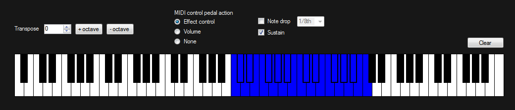
Keyzone window
The keyzone window shows the entire keyboard. A zone is selected by pressing its lowest and highest key simultaneously.
![]()
The keyzone can be cleared by either simultaneously pressing the keyboards lowest and highest keys, or the 'Clear' button. The octave + and - buttons can be used for a direct +12 or -12 transpose.
The midi expression pedal can be routed to its default expression (effect control) channel, or re-routed to the midi volume control.
The 'note drop' options plays a second note one octave down after a selectable interval of 1/8th, 1/4th, 1/2, 1, 2, or 4 beats.
The use of the sustain pedal can be toggled on or off.
Effect plugins
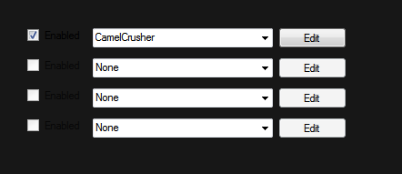
The use of effect plugins is in beta stage. I just finished programming it and ran some successful tests. Up to four effects can be selected for the VSTi channel. The can be enabled by the checkbox. The white effect logo on the VSTi channel control should reflect if any effects are enabled. I can see that it does not work yet as it is supposed to, and I will fix that in the near future. The 'Edit' button opens the VST editor for that VST plugin.
![]()
Discussions
Become a Hackaday.io Member
Create an account to leave a comment. Already have an account? Log In.