Jan Bert
-
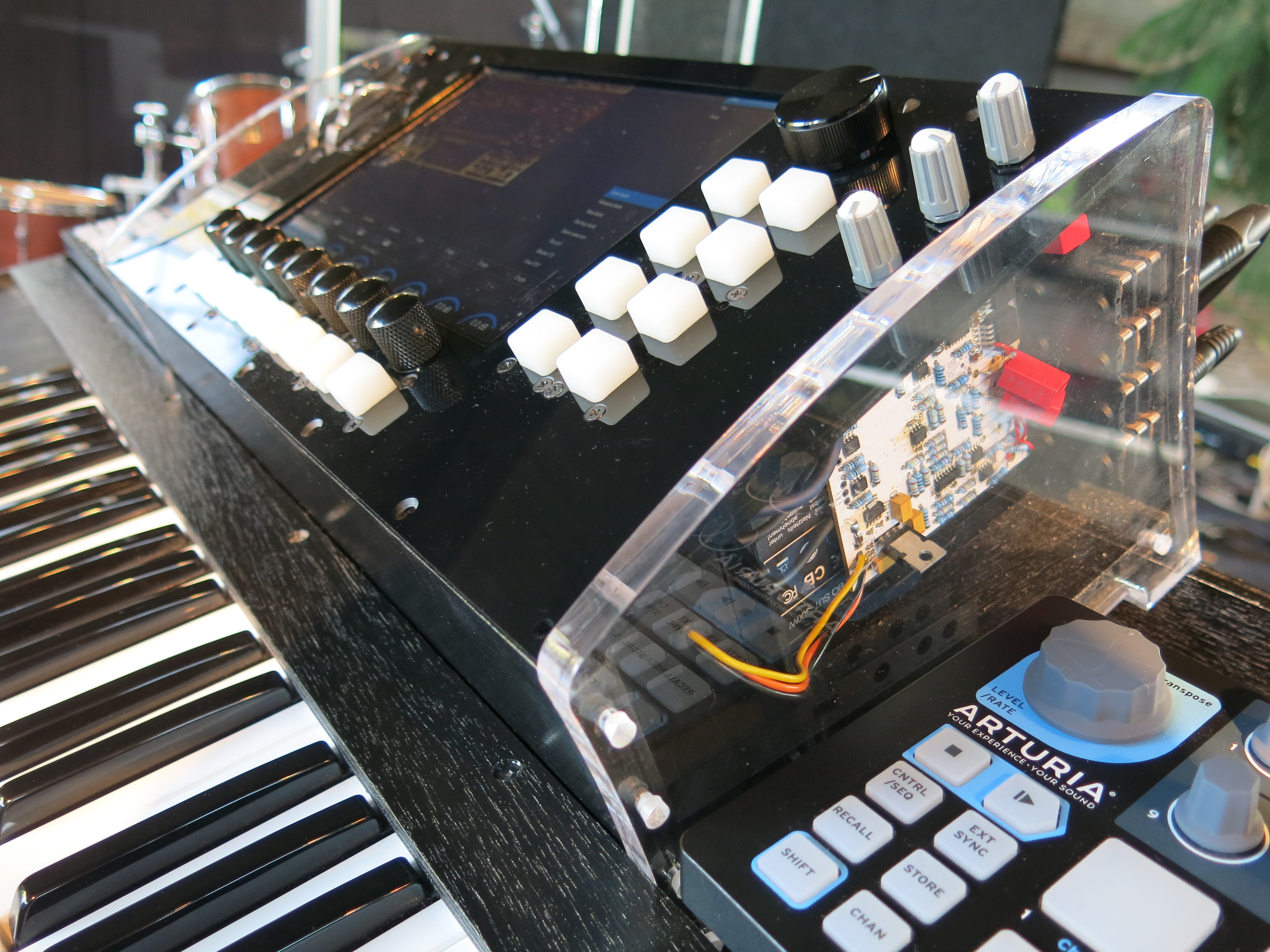
Fatar keyboard prototype
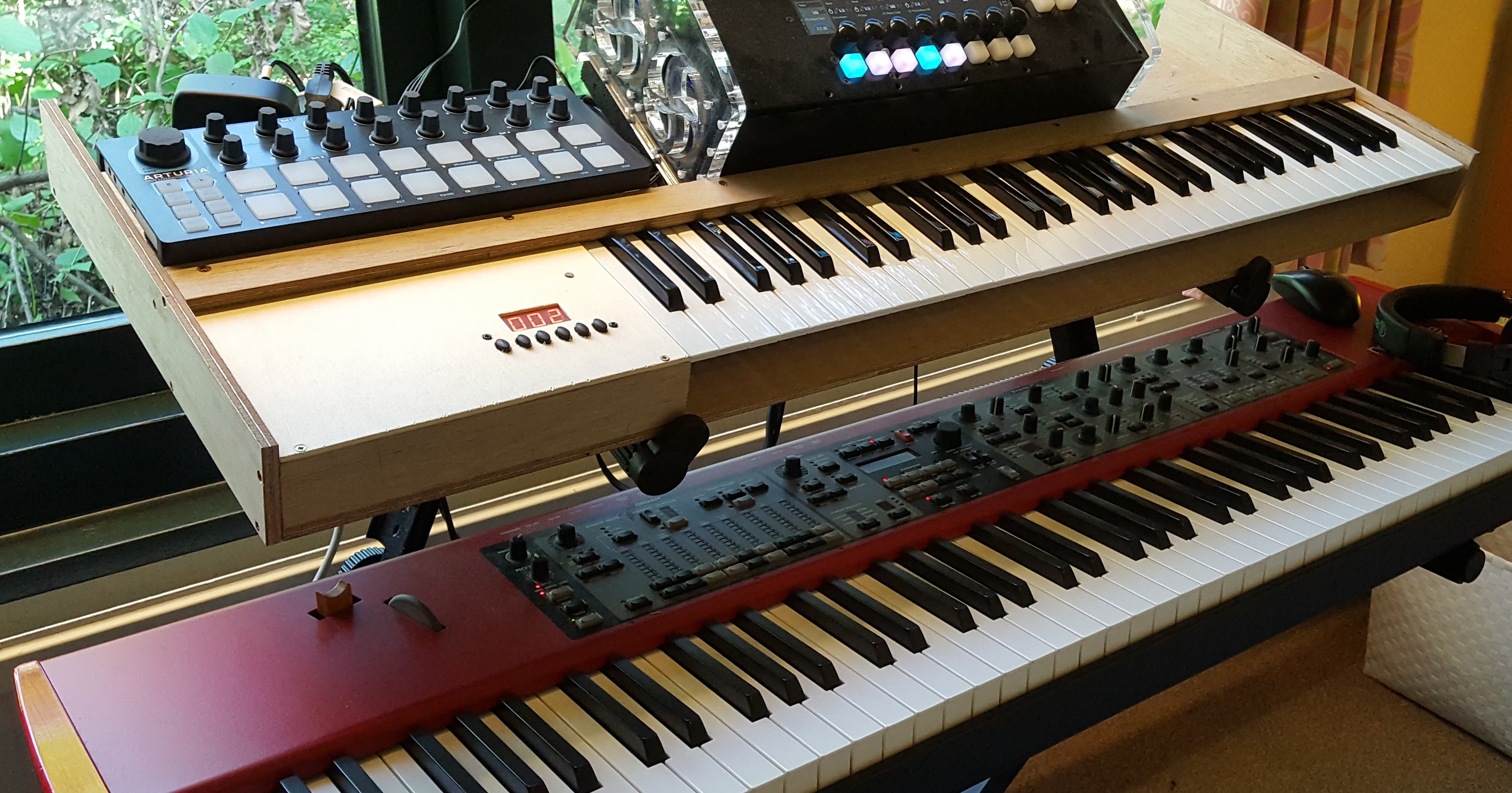
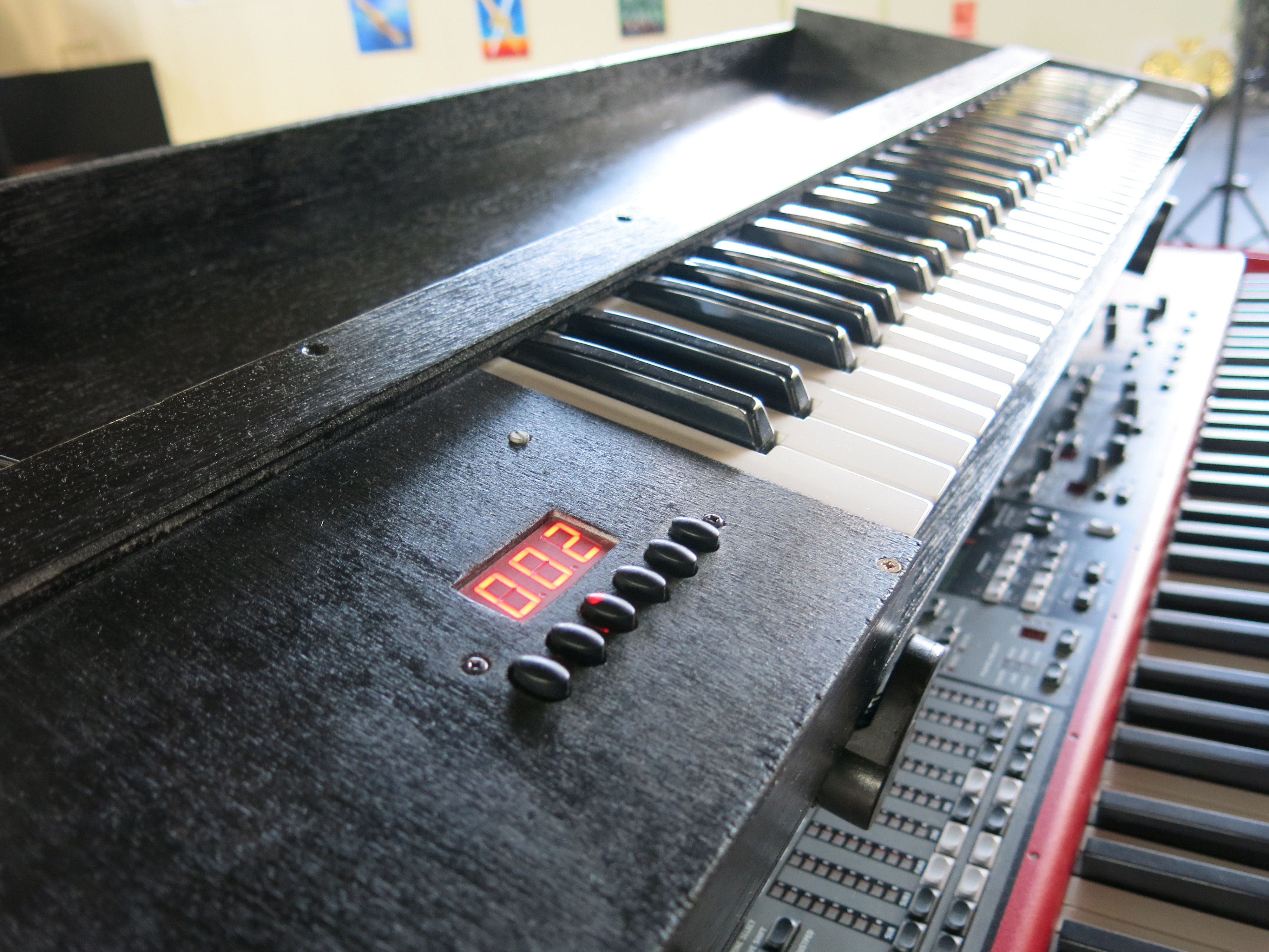
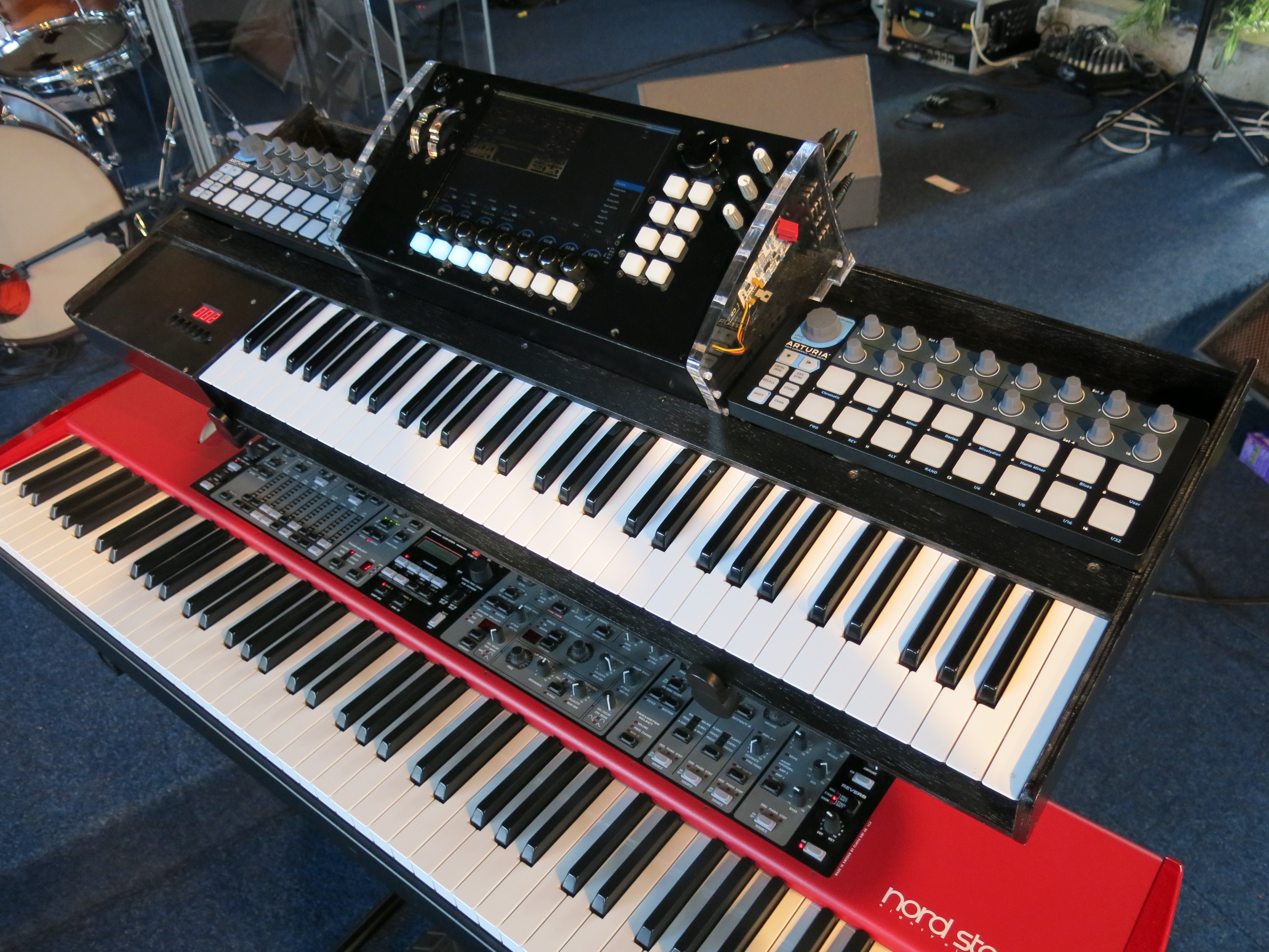
10/18/2018 at 19:55 • 0 commentsFor the 61TP/9S Fatar keyboard I could not find a good 3D model. I did find a dwg, but it is a flattened view of a 3D model and very difficult to convert to a 3D model. Therefore I decided to build a prototype just to get the dimensions for the keyboard right. I ordered some multiplex panels at my local hardware store and put together something quick and dirty. There are no detailed drawings; I just put some numbers on paper to make it big enough. On the left you see one of the two black Arturia Beatsteps. It is connected by midi over USB. I added support for multiple midi input devices in the VST host settings. The midi channel can now be selected for each VSTi channel. I'm using channel 1 for my Nord, channel 2 for the Fatar, and channel 3 for the Beatstep.

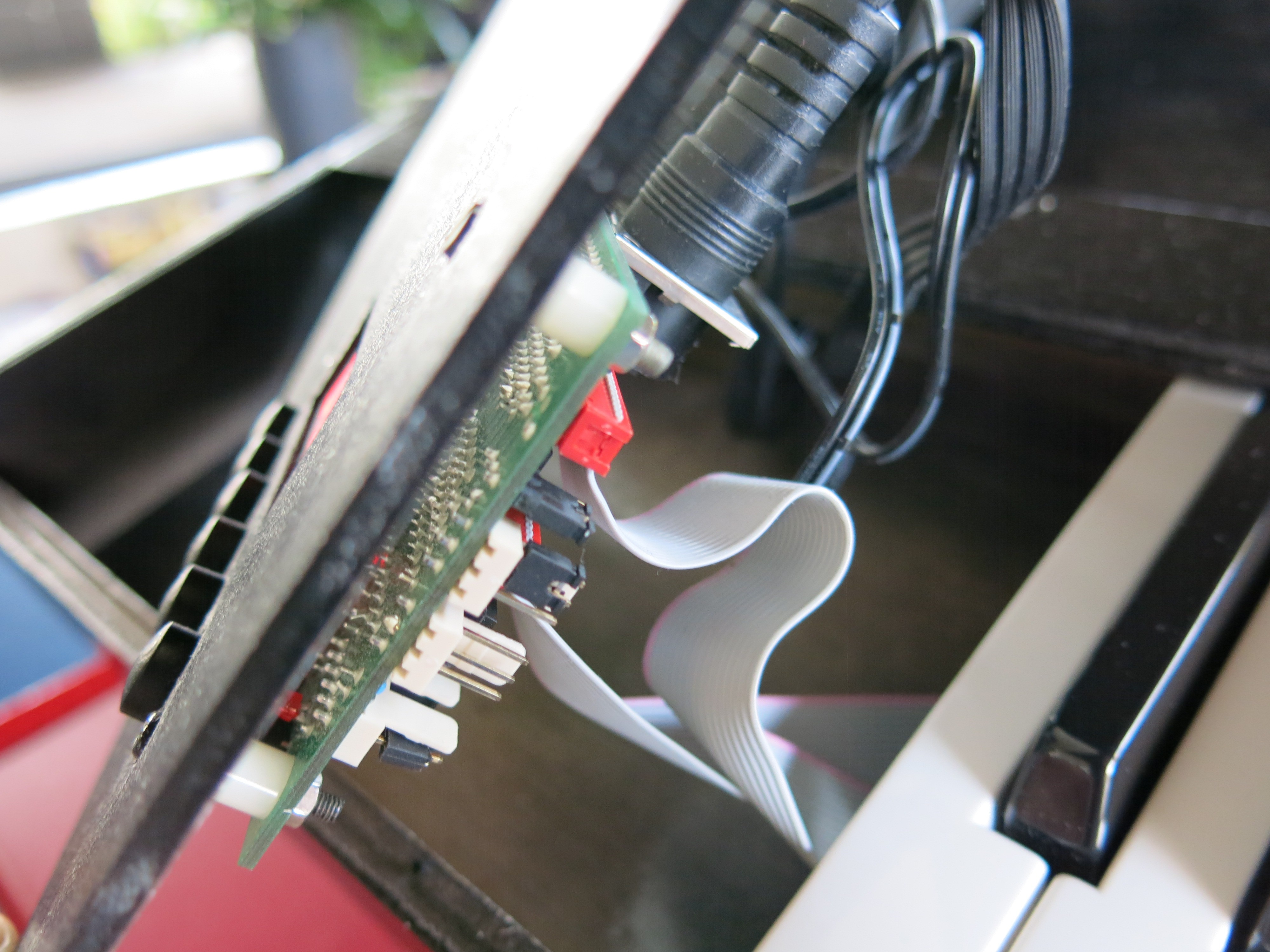
Also, I wanted to know how the midi interface works before I put it in my final design. The interface has a few elliptical knobs that are used to select the midi channel, velocity and other settings. I dremelled out the elliptical holes in a 3mm sheet of triplex. In my final design I'm not going to make the LED display and buttons available on the outside. The board must be configured once correctly, and is then placed somewhere on the inside. It comes with a 12V 600mA adapter which I am not going to use. I will power the board with the 12V that comes from the ATX computer power supply.
I have added some base paint and a few layers of black spray paint to make it look a bit better on stage. While the final VSTiBoard is still in development, this is acceptable as a temporary solution for me right now.
-
VSTiBoard materials
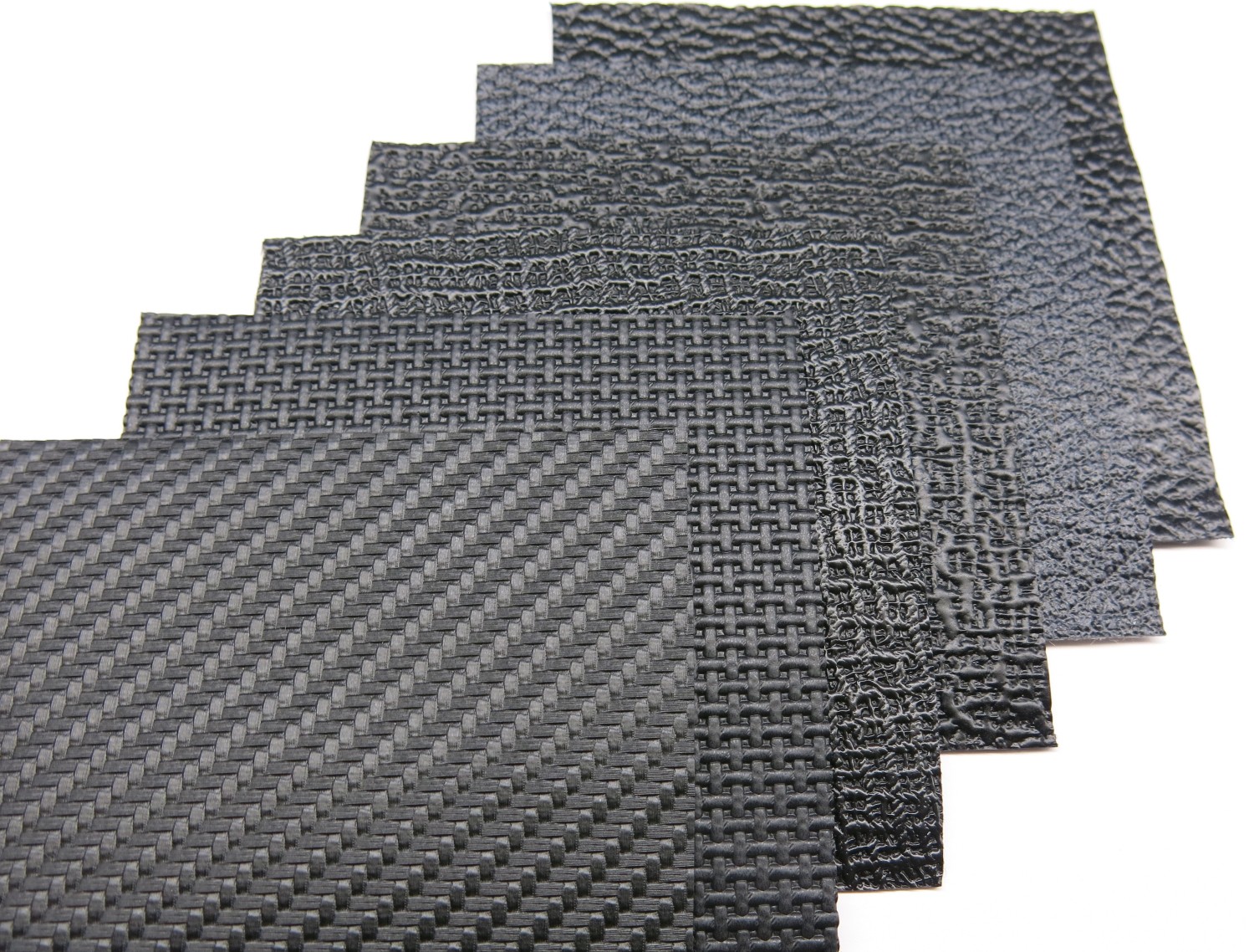
10/18/2018 at 19:15 • 0 commentsThe VSTiBox is made of acrylic and multiplex. For the VSTiBoard I'd like to experiment with some new materials that I have never used before. The backside and panels above and below the Beatsteps will probably made out of thin multiplex covered in Tolex. This is the material that is used to build guitar amplifiers. I have ordered six samples to judge their look and feel. The last two samples in the row are what you typically find on the guitar amplifiers. I have chosen the first one in the row with the carbon look.
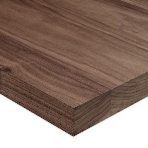
For the wooden side-panels I'd like to use black American walnut. There is a fantastic woodshop in the big city I live in. The place is really nice to look around, and see all kinds of exotic wood. I have to get back there once my drawings are finalized. I’m not a woodworker so I am in doubt if I should hire a professional woodworker to machine the parts according to my drawings.
-
VSTiBoard interfaces
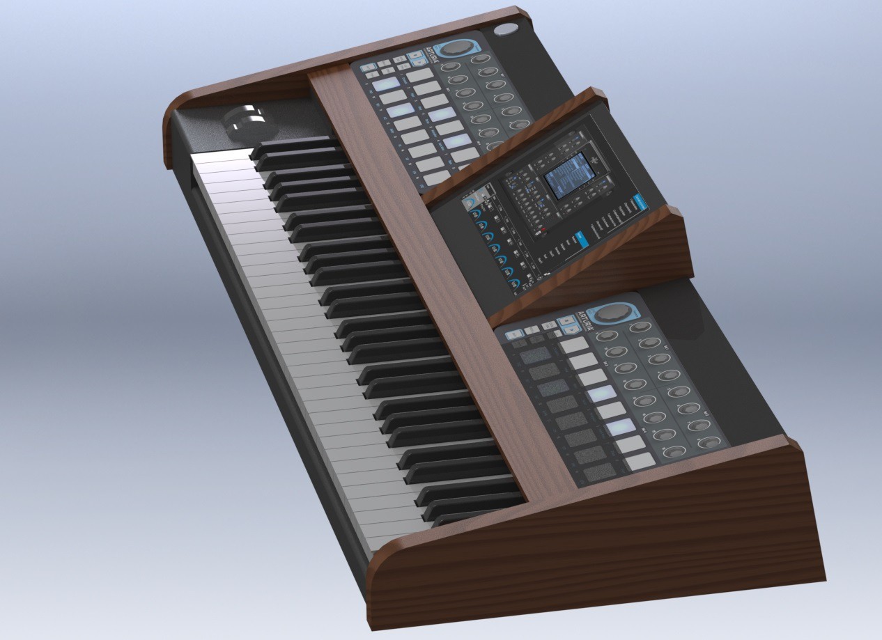
10/17/2018 at 21:09 • 0 commentsIn my latest mechanical design I am using two black Arturia Beatsteps. The size of the Beatsteps causes the overall size of the synth to increase a bit. But this doesn't bother me. Because the Beatsteps have so many buttons and encoders, I am thinking of using the right Beatstep as menu interface instead of the 8 RGB buttons and menu encoder that is currently on the VSTiBox.
The increased width also creates a perfect space for the pitchbend and expression wheels.
The space above the right Beatstep can be used to fit an audio interface and mixer. The problem with my current VSTiBox is that I do not have enough audio input and output channels. I currently do not have a MIC input for vocoder stuff, and I'm using the onboard soundcard + an additional 2 channel USB interface for a clicktrack and backingtrack output. The clicktrack and backingtrack outputs are not ASIO and that gives some time sync issues when starting the track. I have addressed this issue by manually adding some milliseconds delay in the VST host code, but this is not a pretty solution. I'd like to have have an audio interface that handles all input and output channels on the same asio buffer update handler.
My new requirements are:
- 4x line input unblanaced
- 1x MIC input
- 1x Monitor input
- 6x line output balanced
- 1x headphones output
- MIDI in
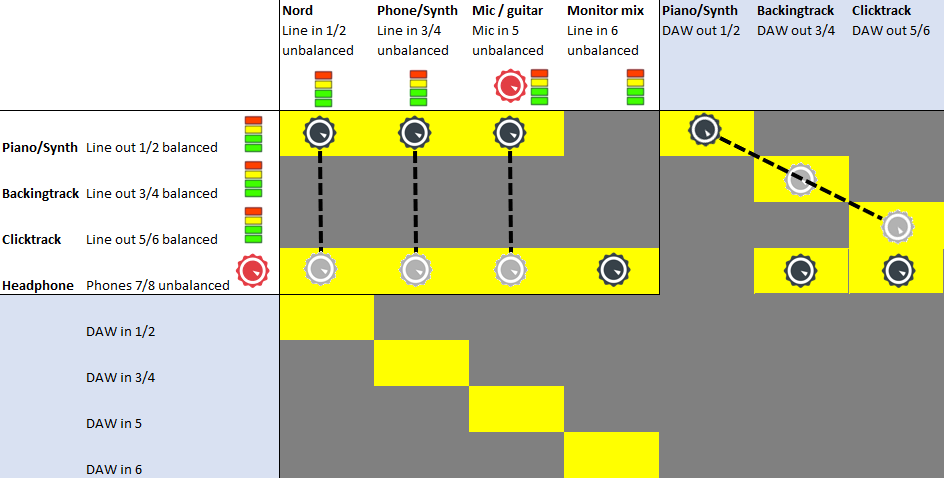
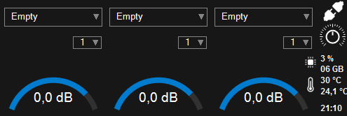
I have drawn a schematic that shows the functional design of my ideal audio interface. The input and output channels have a visual indication on the audio levels. The MIC input and headhone output have a dedicated volume knob. All the other black virtual volume knobs can be controlled by a single big encoder, and some buttons to select the correct virtual volume knob.
To achieve this kind of functionality I’m considering two options:
- Buy a multichannel PCIExpress audio interface like an SERAPH 8 MWX or RME HDSPe AIO PCIe plus a separate MIC preamp and headphone amp. This is an expensive but time saving route.
- DIY custom audio interface. In this way I can have the audio level indicators and volume control exactly the way I want it, and a formfactor which fits the VSTiBoard perfectly.
At the moment I haven't decided yet what it’ll be, but I was recently inspired by freedsp. I have been in contact with one of the contributors and was gifted a bare PCB of the Infinitas. Awesome! The Infinitas is a working prototype of a USB audio interface with up to 32 in- and outputs. I've got the prototype with 2x freeDSPx-BAL-IO-x8 (also on Tindie).
For low latency audio I do not want to use USB, but Ethernet. A latency of less than 0.1ms with UDP over Ethernet is very possible on a Windows machine. I could build an Ethernet controller board with the volume encoders and display options exactly the way I want it. Then use the Infinitas DAC&ADC stage and add a separate MIC preamp and headhone amp. For the controller I'd choose an iMX RT1052 or SAM E70 Cortex M7.
-
VSTiBoard
10/17/2018 at 19:58 • 0 commentsA single keyboard is often not enough when playing keys in a band. The VSTiBox supports a keyzone definition for each VST channel, but this results in way to many zones on my Nord. Also, there is no visual indication to where a zone starts and ends. I have to simply remember where each zone is. The Novation SL MkIII midi keyboard has a very neat feature to tackle this problem: RGB leds to indicate to which zone each key belongs to. Unfortunately my 1st gen Nord does not have this. My solution is to add a second keyboard.
Though I own an Access Virus KB, I’d rather not take it to a rehearsal or gig because it is just another piece of equipment that has to be hooked-up. The whole idea of the VSTiBox is to bring as few components as possible and to connect as few cables as needed. Another thing that I was missing when playing the VSTiBox was a drumpad to trigger some samples, and a few additional encoders to control the VST instruments or additional VST effect plugins in the signal chain.
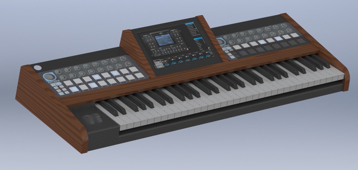
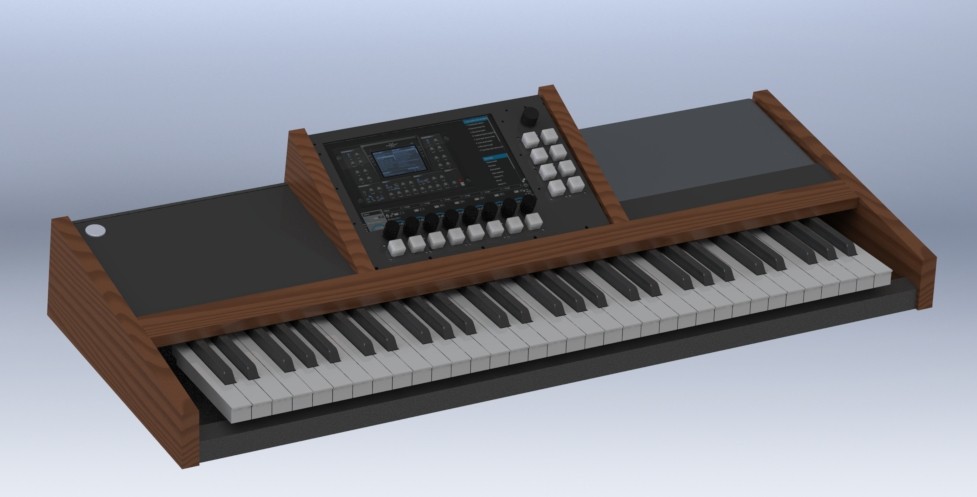
Therefore I decided to design a new version of the VSTiBox: the VSTiBoard!This is my first attempt of the VSTiBoard, which has a keyboard and all the parts of the VSTiBox.
Keyboard
After some browsing I decided to use a Fatar keyboard, because it simply has the best quality and feel you can get. It is also one of the very few keyboards which you can buy as OEM part. Some of the Fatar keyboards come with aftertouch. This is something that I want to have. So I tried to get a Novation SL mkII keyboard with aftertouch as service part from a local music shop. That didn’t work out. The only Fatar keyboard I could find was the 61TP/9S from http://www.doepfer.de, sadly without aftertouch. Maybe I can figure out a way to place a linear soft-pot (ribbon sensor) below the keys to build my own aftertouch. The advantage of using the keyboard from Doepfer is that they offer a board that converts the Fatar signals to midi, which includes the velocity calculation. I am not afraid to build this myself, but using off-the-shelf parts will save me a lot of time.
Touchscreen
This time I am using a touchscreen, because I was using my mouse way too often when defining a setlist, naming banks or checking out new VSTi’s. I have bought a 10.1” 1920x1200 LCD (B101UAN02.1) which comes with a very detailed manual that contains all the dimensions and tolerances, which is helpful for 3D development.
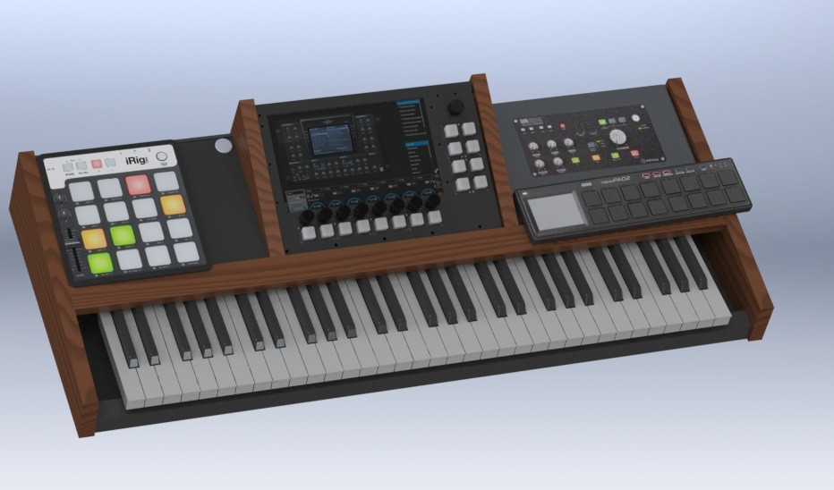
MIDI controllers
In order to see which midi controllers suited my design best, I decided to draw them.
In the image above you see a Steinberg UR28M, of which I thought was the perfect solution for an integrated mixer and audio interface. I bought a secondhand UR28M and tested it on the VSTiBox. The CPU load was 40% at idle! What was going on?
It turned out that the asio handler was called at a very irregular interval. I tried different buffersizes, driver updates, and even the asio4all driver. Nothing solved this issue. The ESI Juli@ does not have this problem and the asio handler is always called at almost the same interval, give or take a few ticks. When suddenly there is less time to process the VSTi's there is a big change that the buffer update is not handled in time which in return results in a crackling noise.
-
CPU load monitoring
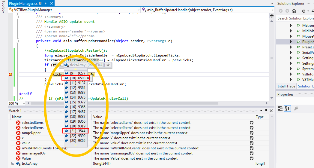
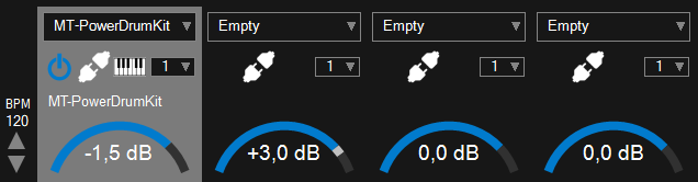
10/17/2018 at 19:38 • 0 commentsThere is a CPU load monitor in the bottom right of the main screen of the VST host.
It doesn’t show the overall CPU load like Windows Task Manager, but the actual system load for updating VST's and processing the audio buffers. The idea is to measure the duration of all the processing in the ASIO buffer update handler. To do this, a stopwatch is used which is restarted at the beginning of the handler. At the end of the handler function call, the elapsed time inside the handler is compared with the period of one ASIO buffer update, all measured in ticks.
private Stopwatch mCpuLoadStopWatch = new Stopwatch();

...
stopWatchTicksForOneAsioBuffer = (long)(Stopwatch.Frequency / (mAsio.SampleRate / mAsioBuffSize));
...

private void asio_BufferUpdateHandler(object sender, EventArgs e)
{
    mCpuLoadStopWatch.Restart();

    ... VST processing and buffer updates

    int cpuLoad = 0;
    long elapsedTicksDuringHandler = mCpuLoadStopWatch.ElapsedTicks;
    cpuLoad = (int)(elapsedTicksDuringHandler * 100 / stopWatchTicksForOneAsioBuffer);
    if (cpuLoad > mMaxCpuLoad)
    {
        mMaxCpuLoad = cpuLoad;
    }
}
The maximum CPU load is read and reset by the UI thread on a regular interval. The idle CPU load is currently 3%. This is a bit high. There are a number of things that are not so efficient here:
1. The programmer :) I’m sure there are still many optimizations possible. I have not used any profiling tools yet. I’ve tried to use unsafe pointer based buffer handling as much as possible, but I have not deeply reviewed what I put together yet.
2. The jump from unmanaged to managed C# code.
3. Garbage collection.
When running a single lightweight VST, the CPU load is about 8%. I'm thinking of rewriting the entire VST plugin and audio buffer update handling in C++. This would also allow me to implement multicore processing with a dedicated audio thread on each CPU core.
-
Mechanical design
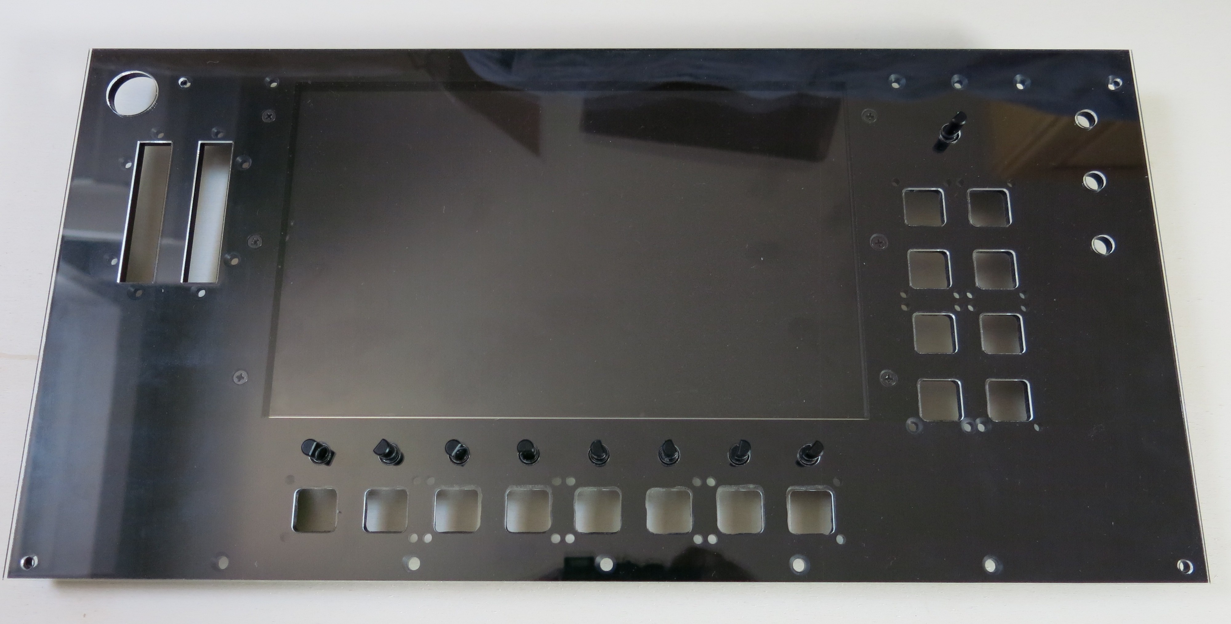
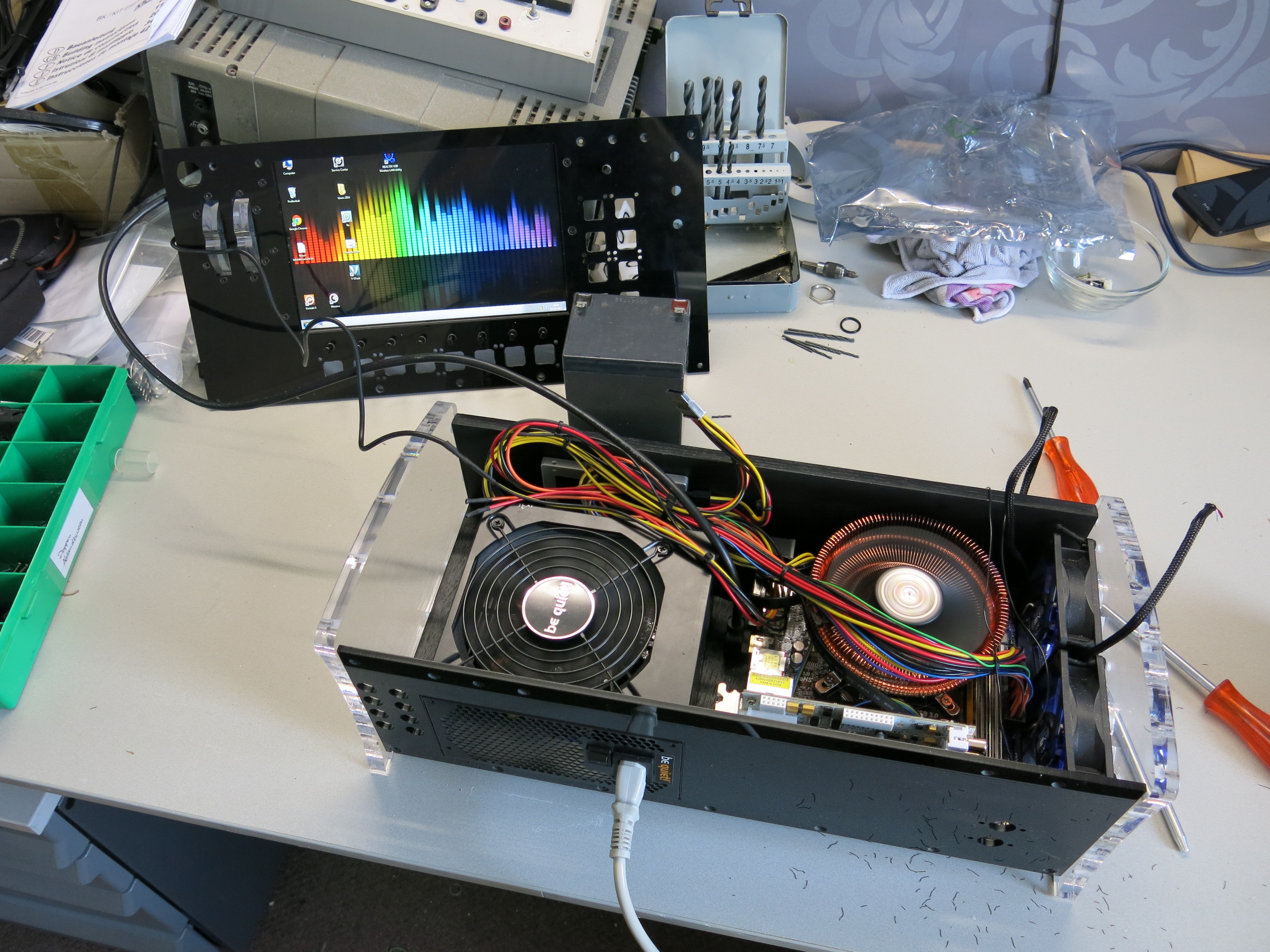
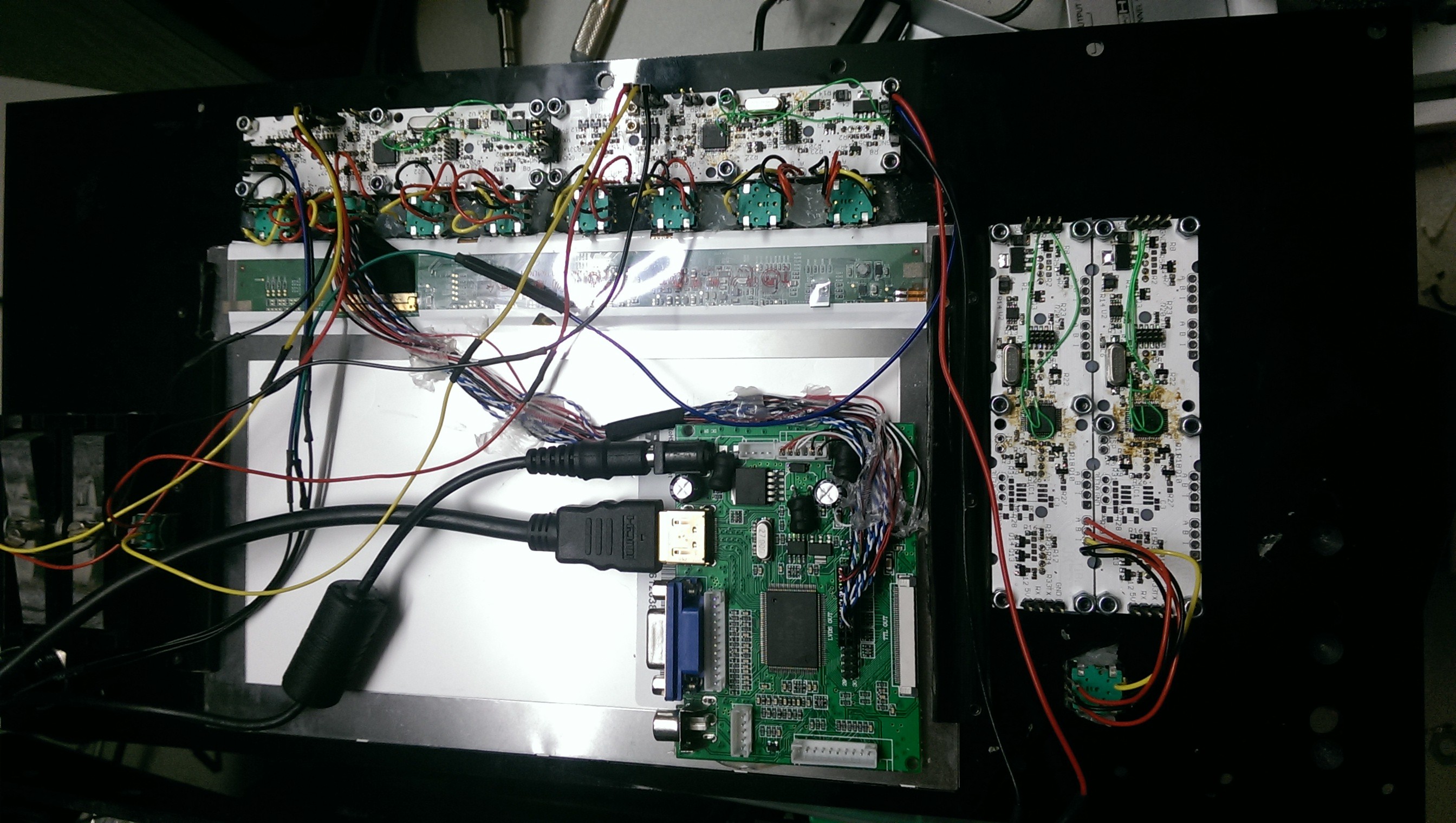
09/08/2018 at 15:54 • 0 commentsThe biggest parts of the VSTiBox are a 10" LCD, the micro-ATX with the copper Zalman cooler and an ATX power supply that need to be stuffed in all one box. The top plate with LCD is put at an angle for better readability of the screen. The form-factor of the mixer matches this angle, with the volume controls on top and the TRS connectors on the back.
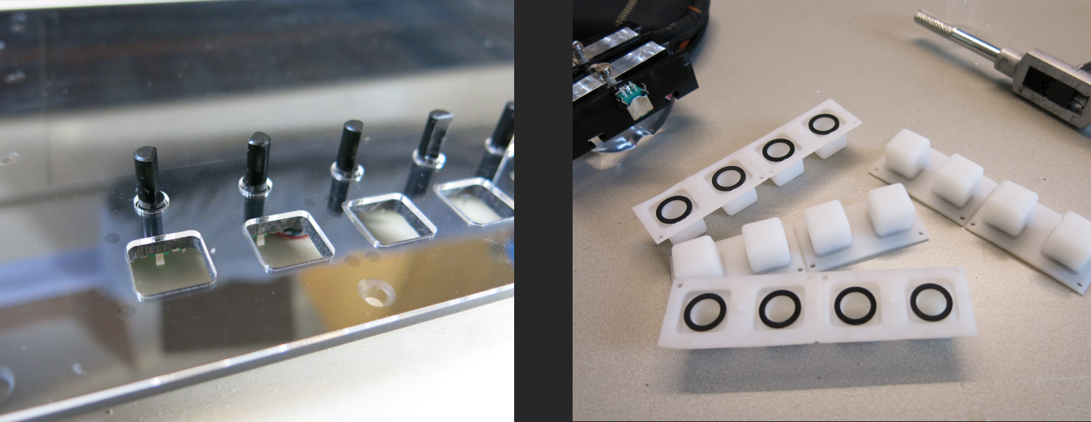
The LCD screen is covered with a 1/16" clear acrylic panel. The 1/16" clear panel has the same cutouts as the 3/16" black panel below it, except for the LCD. The square cutouts are for the silicon buttons. I dowloaded the stepfile for the silicon buttons and added some tolerance for the cut out. When assembling the top panel I noticed that the silicon buttons were a tight fit and needed at least 1mm more clearance. After a lot of tedious filing work on the black top panel, I did not want to work on the clear panel anymore, so it is currently not mounted.
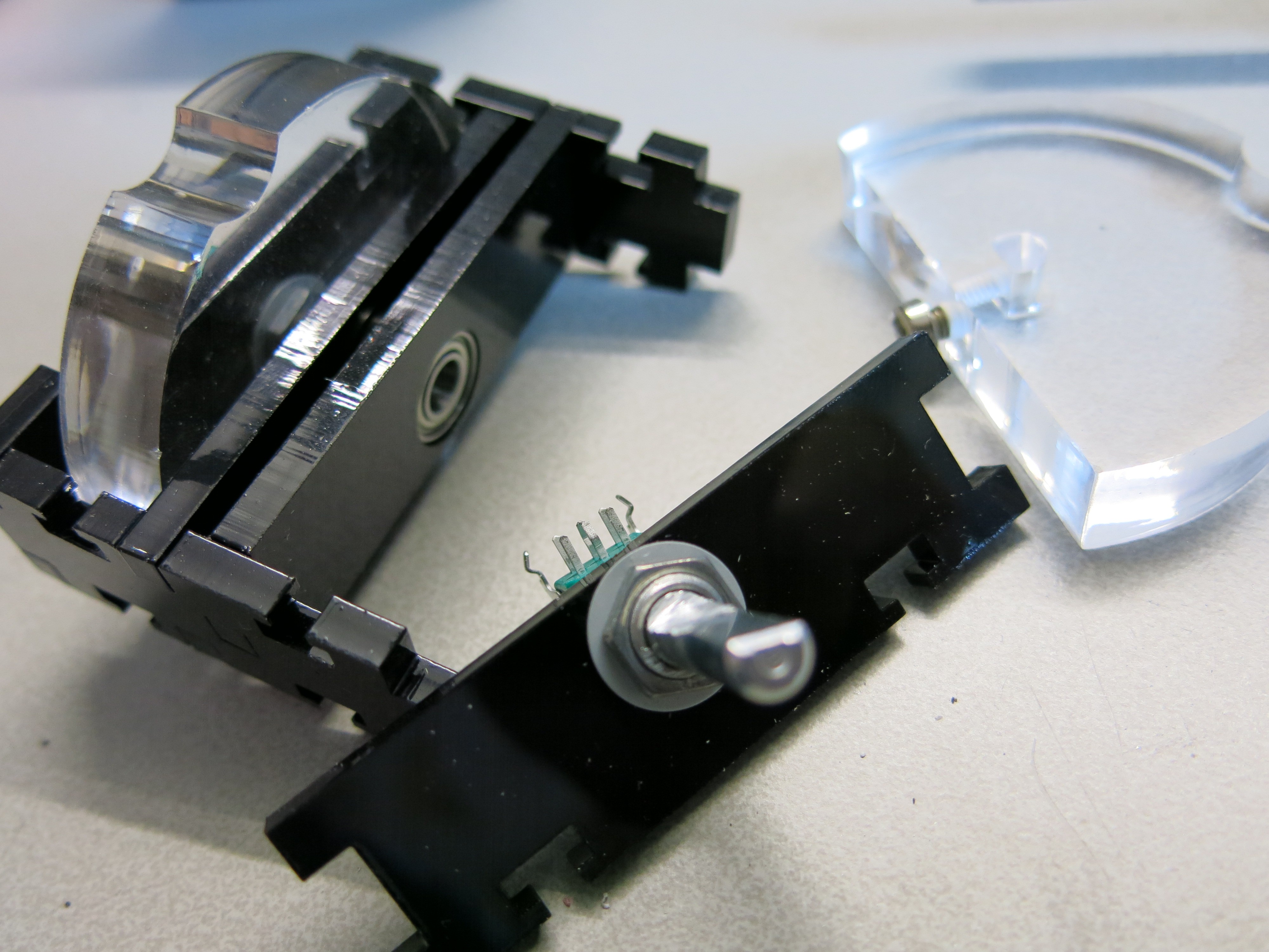
On the top left I added an illuminated power button. Below that are two control wheels for pitch bend and expression. Two 1/2" acrylic wheels are mounted on a potmeter shaft by a bolt on the bottom side in a threaded hole. The far end of the shaft ends in a bearing for strain relief. The bearing has a tight fit and is held in place by its surrounding components.
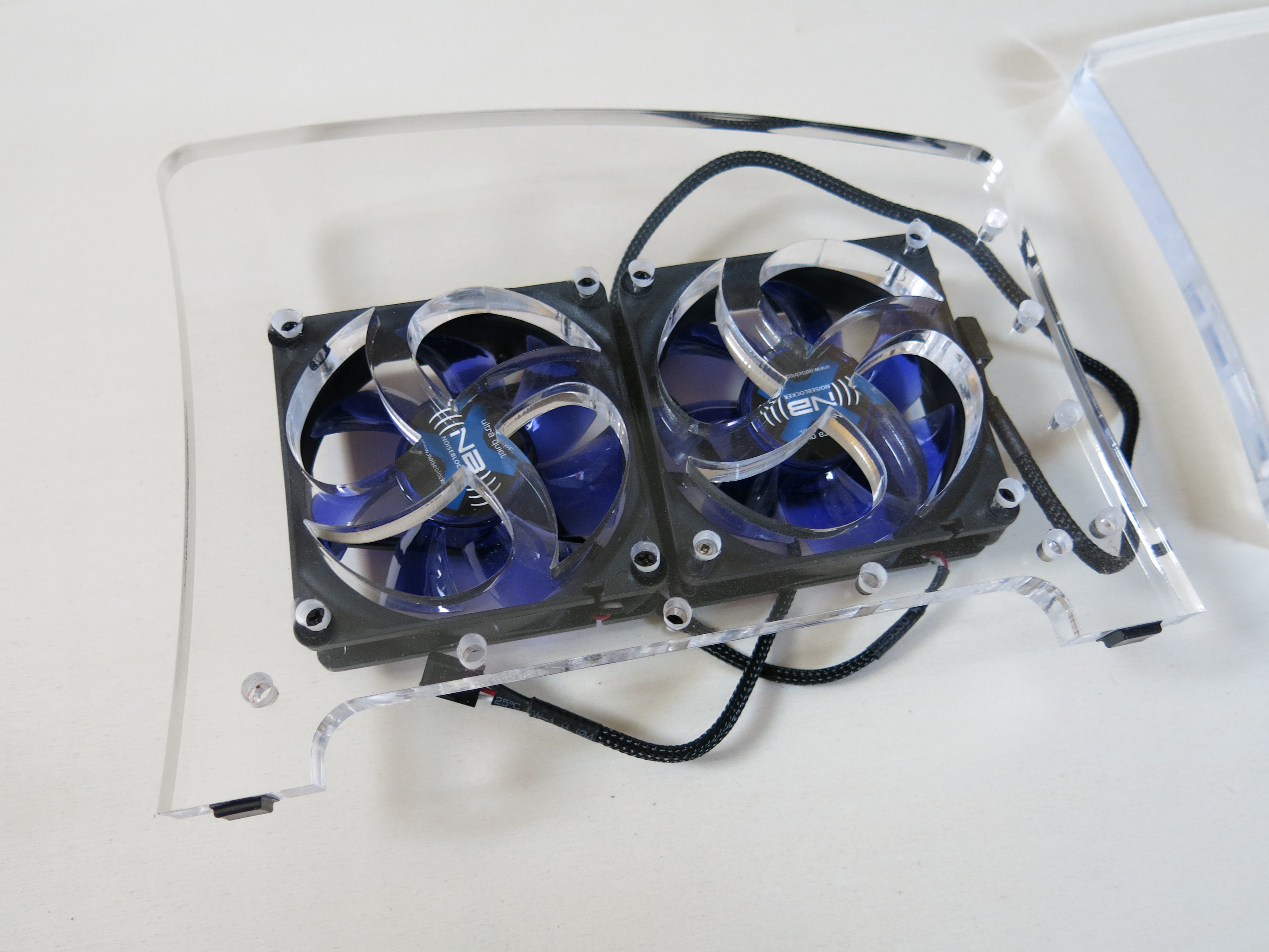
The bottom and front plate are made of 14mm plywood which give the box it's strength. The back and topside are 3/16" black acrylic. The side panels are clear 1/2" acrylic which outer shape is slightly curved on all sides. I wanted the right side panel to be clear so you can see the DIY mixer. I choose a white PCB color, but maybe black would be the better choice. On the left side, two 80mm silent fans with low RPM are mounted (Noiseblocker BlackSilentFan X-1).
Below is a picture of the first boot of the computer after assembling it in the box. I did not measure the height of the fan correctly and had to dremel out some space in the 14mm bottom, which left about 5mm of wood below the area of the cooler mount.
-
C# VST host (DAW)
09/07/2018 at 17:15 • 0 commentsFor quick prototyping C# is a great language. For highly optimized real-time audio processing C++ is the better choice. Nevertheless I wanted C# as the language for my custom VST host (often called DAW) because of the relatively quick development time and the large number of libraries that I could use. C# offers support for unmanaged code with which you can still use pointers to process audio in a relatively efficient way.
VST plugins
I used VST.NET (https://github.com/obiwanjacobi/vst.net) to load the VST plugins, write midi messages to it and get the audio buffer. The guy who wrote this stuff has put some serious time and development effort in it for which I am very grateful. The only downside is that plugin processing runs from a single dispatched thread. That means that all simultaneous VST's that run in my host are processed from that single thread. I think that the bigger VST's handle their own threading and this is not a problem, but when you are using VST's that only run on the thread from which they are called, this is a serious downside. This problem is discussed in the forums and no solution exists.
I will keep my eye open for other VST host libraries written in C++, and am probably going to rewrite the whole audio processing in pure C++ and keep the GUI layer in C#. Nevertheless I am very pleased with the current performance of my software. I am able to run four heavy plugins simultaneously at a buffer size of 128 samples. Often I can use some more medium weight plugins and use all 8 channels. Effect plugins are also supported. I tested it briefly and it is basically working, but I consider it to be still under development.
ASIO
For Asio handling I tested both BlueWave.Interop.Asio (https://www.codeproject.com/Articles/24536/Low-Latency-Audio-using-ASIO-Drivers-in-NET?msg=4526889) and NAudio. Both work fine, but the BlueWave performed better to my opinion. I say this with care because it could very well be the same code base. I haven't looked into the code behind the NAudio asio handling. The BlueWave project had a small bug with did not terminate the ASIO driver correctly at shutdown. This resulted in having to reboot every single time after shutting down a debug session in order to get the audio to work again. After I got tired of doing so, I decided to fix the bug. The updated source is on my github.
MIDI
For MIDI input from my Nord and an Arturia Beatstep, I tried to use midi-dot-net (https://code.google.com/archive/p/midi-dot-net/). Unfortunately the Juli@ does not support kernel32 winmm.dll midi! The only way I could get MIDI in and output was to use DirectMusic midi. For that I used DirectMidi.net (http://directmidinet.sourceforge.net).
UI controls
Most of the UI controls I have written myself. The ringslider above the physical encoder was one that was very specific. Also the scroll-list operated by the main menu encoder I build myself.
Hardware monitor
To monitor the CPU temperature I used OpenHardwareMonitor (https://openhardwaremonitor.org) which continuously displays the temperature in the main screen. When installing the CPU cooler I damaged the bearings and decided to just remove the power from the CPU cooler. Amazingly it always runs cool. Possibly beacuse of the airflow through the case. But because of this I wanted to see the CPU temperature at the main screen.
PDF Viewer
Sheet music in PDF format can be added to a song (bank). I use PDFViewer from https://www.codeproject.com/Articles/37458/PDF-Viewer-Control-Without-Acrobat-Reader-Installe to to display it.
Smooth instrument transition
I personally find this the most interesting part to write, because I came up with a unique musical feature that I haven't found in other DAW software for live usage. When a channel is enabled, the button is illuminated blue. When the button is pressed the state of the channel goes to 'pending disable' . The sound does not directly go away but keeps on going as long as the keys or sustain pedal remain pressed. New keys will not play on the 'pending disabled' channel. Once all the active keys are released the channel state goes to 'Disabled'. In this way you can very fluently change between different sounds. I recently found out that the latest Nord Stage3 also has this feature, but hey it cannot run VST's :)
Other features
I'll just name a few other interesting features I implemented:
- Synchronized backingtrack + clicktrack with bpm midi clock (2x additional stereo out). In this way I can play synth arpeggio’s when a backingtrack and clicktrack is running.
- Midi active keyzone per channel.
- Transpose per channel.
- Foot controller selection per channel; volume, expression or none.
- Midi channel per (instrument) channel. I needed this since I started using a 2nd keyboard.
- Setlist editor.
- Metronome based on high resolution media timer.
- Recording & playback of audio output in MP3 format.
-
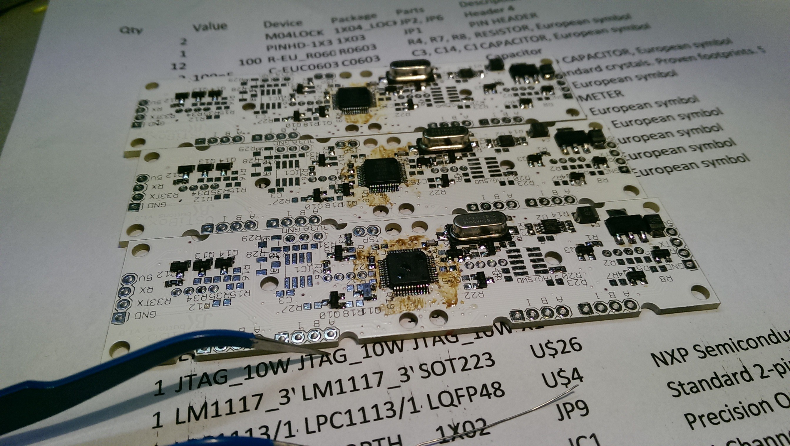
Controller
09/07/2018 at 15:04 • 0 commentsBelow the LCD I needed 8 encoders in a row, with illuminated buttons below them. On the right side of the LCD, I also needed 8 illuminated buttons, but in a 4x2 configuration. Therefore I designed a custom PCB with 4 encoder inputs and 4 pads for silicon buttons each with an RGB led behind them. I bought the silicon buttons at Sparkfun.
The heart of the controller is a LPC1114 with the UART hooked up to a 4 pin header. Both sides of the PCB have the same header with power and UART RX+TX, so multiple controllers can be chained. The idea is that the controllers are hooked up in this way for receiving messages from the PC:
- PC TX => Controller 1 RX
- Controller 1 TX => Controller 2 RX
- Controller 2 TX => Controller 3 RX
- Controller 3 TX => Controller 4 RX
And for transmitting messages to the PC:
- Controller 4 TX => Controller 3 RX
- Controller 3 TX => Controller 2 RX
- Controller 2 TX => Controller 1 RX
- Controller 1 TX => PC RX
That means that controllers 1-3 are acting as a relay. Message are received in a queue on interrupt basis, and also transmitted on interrupt basis to offload the CPU in all the passing messages from the other controllers. The protocol supports an incremental ID which is assigned during initialization. This ID is used in each message to communicate with the correct controller.
The board also contains a SE95 for SPI temperature sensing. An OPA177S with two micro pots is added for reading the pitch wheel pots with an adjustable gain and offset, so the ADC can be used in almost its full range.
Unfortunately I made a mistake in the schematic and did not hook up the UART RX&TX to the microcontroller. That is why you can see the various thin green wires.
-
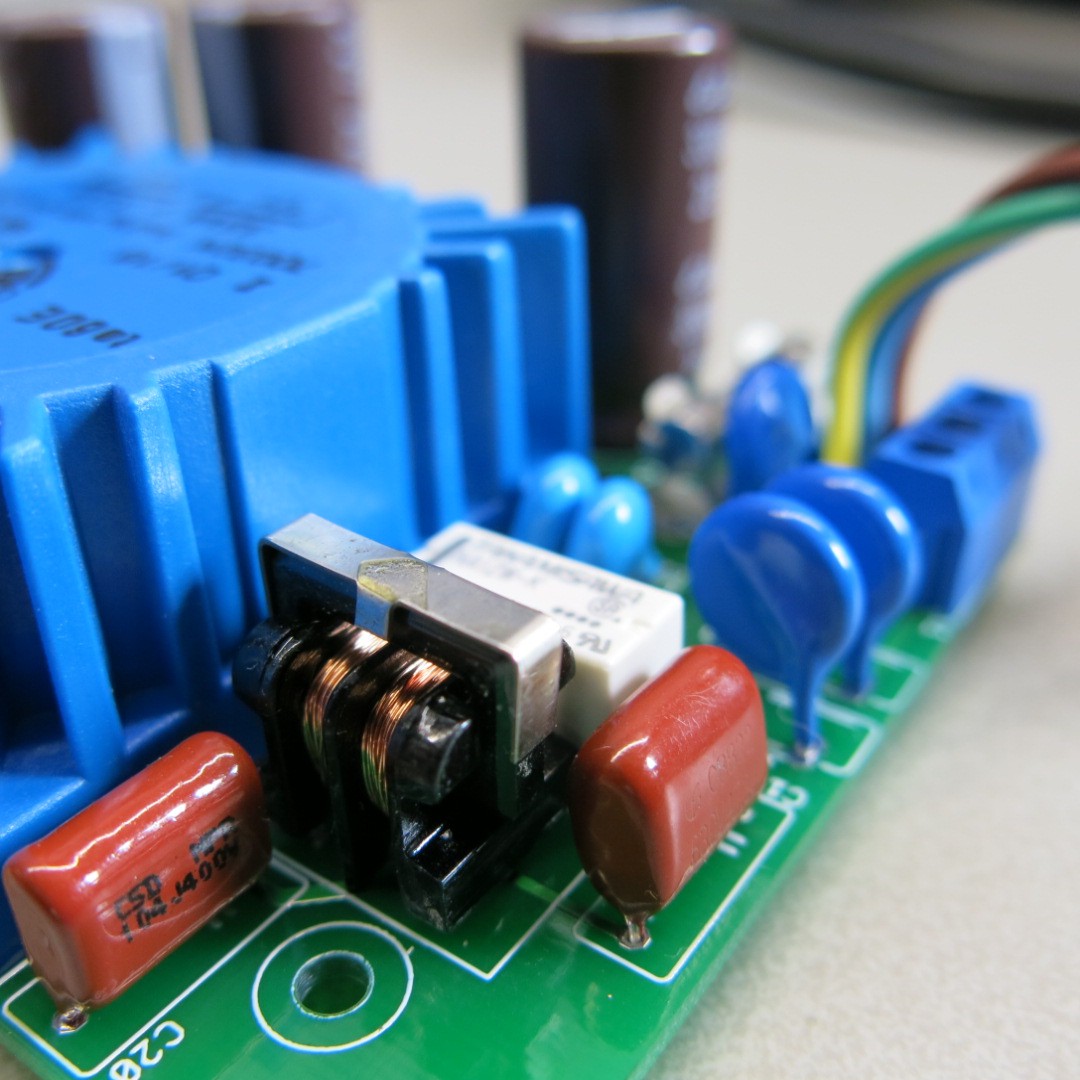
Low noise PSU
09/06/2018 at 20:58 • 0 commentsIn order to check if the noise from the mixer originated from the +/-12Vdc ATX computer supply, I decided to build a standalone ultra low noise PSU that could fit in the VSTiBox case. Of course pre-build solutions were available from ebay&Ali, but they did not exactly fit my requirements and size restrictions.
I wanted the PSU to be a slave of the ATX computer supply, and added a relay which is powered by 5V from the ATX.
The 230Vac input is filtered by 3 varistors, a common mode choke and some class Y caps. I choose a 5VA toriod transformer with 2x12Vac output. The output is rectified by very fast super low Vf schottky's with 100nF in parallel, which acts as a snubber to prevent HF ringing. Another single HF snubber is placed after the bridge rectifier. The TPS7A4700 linear regulators are simply the best I could find in terms of noise. The output stage has several different caps, with one big 4700uF buffer.
Because this is a 230Vac circuit, I made sure to separate the low voltage domain by at least 4mm, and the high voltage signals at least 2mm.
This design is a first time right, with no modifications needed. I tried to measure it with a high-end scope with the probe set to 1:1 and AC input, but could not find any output noise.
When I powered the mixer with this ultra linear PSU instead of the ATX, the noise (which was already quite low) only slightly decreased. I think it now compares to other instruments like my Nord. Overall I'm pretty pleased with the result, though this ultra linear is an absolute overkill. If I were to design the power supply again specifically for the mixer, I would have chosen the same toroid and filtering, but a simple 2x LM317 will do just fine.
-
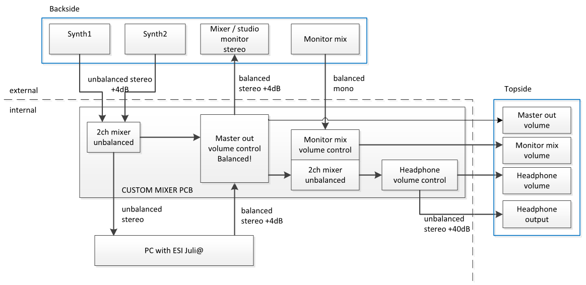
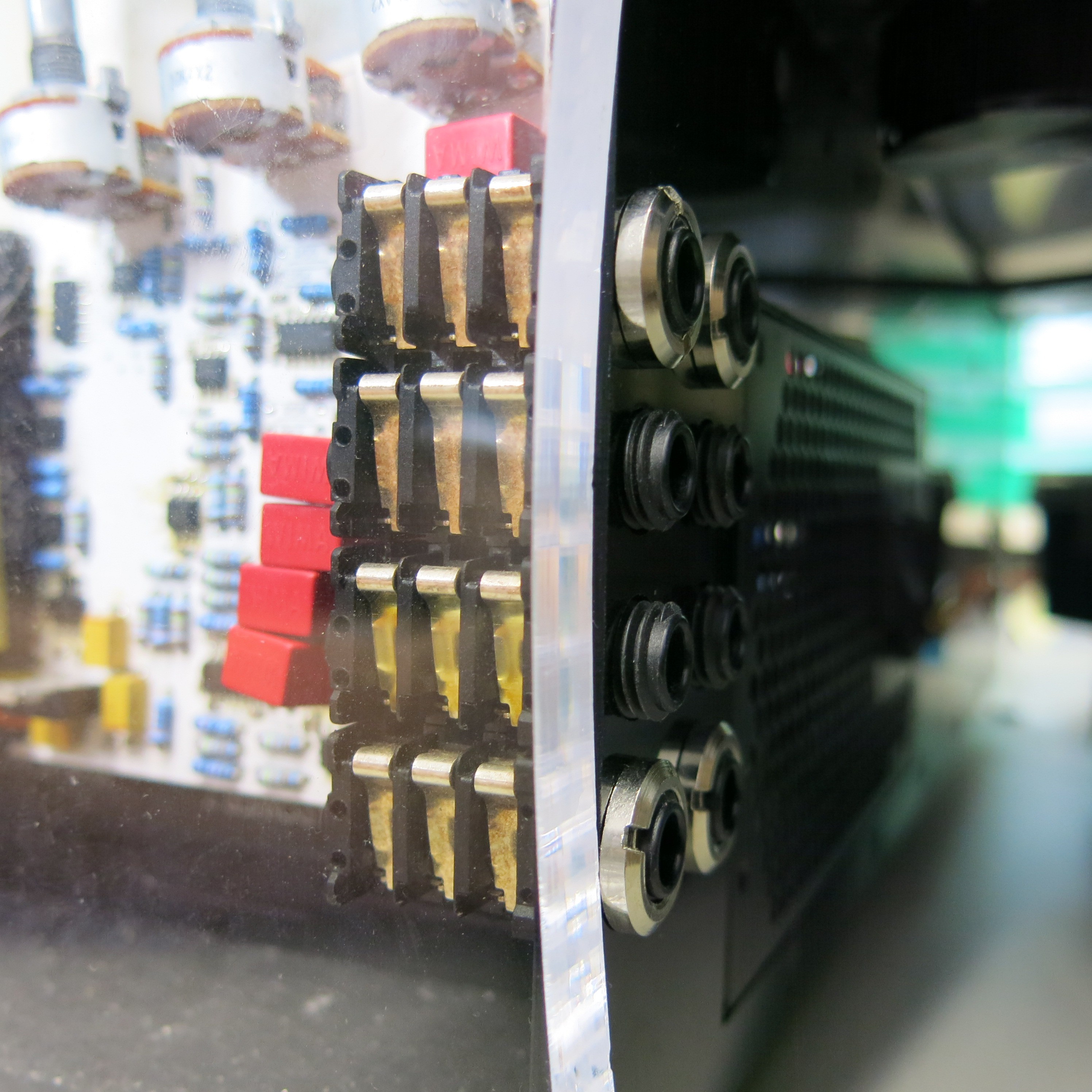
Mixer design
09/06/2018 at 19:50 • 0 commentsThe ESI Juli@ audio interface provides a single stereo input and output. Simply providing TRS connectors to the backside of the enclosure for the audio interface isn't enough. A mixer is needed to combine the signal of my Nord stage and Access Virus kb with the VSTiBox output, and send only one stereo mix to the mixer table. When playing in more professional bands this is not an issue because the sound guys like to receive multiple separate synth channels so they can can make their own mix, but in the places I perform it is better to do the mixing myself. Also a headphone output is needed. A monitor input with signals from the rest of the bandmembers is routed to the headhpone output only. I made the following design of the audio routing for the mixer before diving into schema and pcb design:
In the final design the headphone output has moved to the backplane. Also the audio to the Juli@ is balanced. This is the first audio design I have ever made, but I got some help from an expert for which I am very thankful. I tried to design it reasonably HIFI, with no sacrifice on cheaper parts.
I did some research on good sounding opamps and settled for the LME49740 for quad and LM4562 for dual opamps. Generally I chose the feedback resistors to be <= 10k, and lower when possible, with a matching capacitor to create a low pass filter with -3dB at 150kHz just to prevent high frequent ringing.
The power supply consists of the TPS7A4501 positive and TPS7A3301KC negative utra low noise linear regulators. Both have a 220uF low ESR tantalum buffer cap. I designed the power stage for +/-12Vdc input, and +/-10Vdc output, so all the opamps and the headphone amp operate on +/-10Vdc.
The headphone amp is made of a pair of LME49600's, each with their own servo circuit for removing a DC component.
The output of the volume control potmeters have a 100k pull down to prevent a cracking noise when turning them. I chose audio tapered potmeters that fit on angled side of the pcb. The pcb has the same angle as the top side of the case. The back side contains 4 dual row stereo Neutrik connectors for in- and outputs which are mounted in place by a nut. The line inputs are routed through 4.7uF polyethylene WIMA caps (MKS2B051001N00MSSD) for decoupling which according to some HIFI forum posts sound best. For the same reason I have used metal film caps and through-hole resistors. That didn't bother my because I had to solder the PCB by hand anyway. It also made routing easier I think, because all the through-hole components create a kind of 3rd board layer.
During assembling and testing I discovered a few mistakes:
1. The footprint of the caps was wrong, but this was easily solved.
2. I made a mistake in copying the servo circuit for the LME49600 from its application note, which resulted in a damaged earphone. Fortunately not a damaged ear!
3. If I recall it correct there is an error in the gain of the input stage from the Juli@ (L+R balanced input). But I still have to figure that one out. For now I can sufficiently adjust the level with the volume potmeter.
4. There is a mistake in one of the mounted resistors; the left and right master output differ 3dB. I'll have to fix that too. All the sound guys I have worked with are annoyed that they have to unbind their stereo channel and use separate gains for left and right. If you read this: I'm sorry ;)
5. Noise. I can hear it very little, but I want it to be just dead silent. To figure this one out I have built a custom ultra low noise PSU instead of the +/-12Vdc coming from the ATX computer supply. I will discuss the PSU in a next log.