T. B. Trzepacz
-
Case update
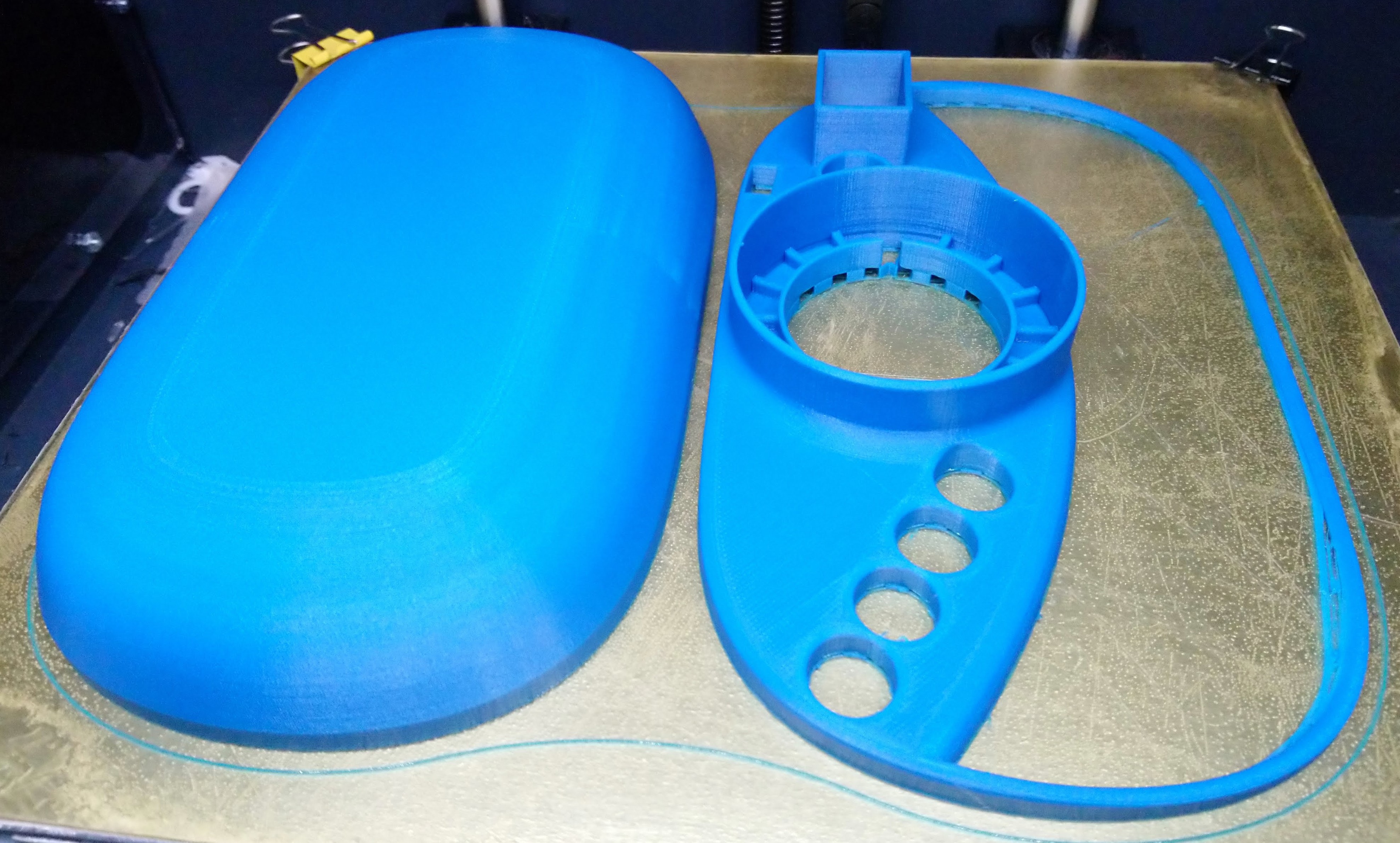
10/09/2018 at 15:32 • 1 commentI thought I'd take a few minutes to fix a couple of problems with the original case design and do a 2nd 3d printing, but I ended up spending all night on it.
![]()
![]()
A larger bezel means it might actually fit together properly. this time.
I added alignment nubs and screw holes with proper recesses in the bottom for the screw heads.
There are now proper holes in it for the stylus and USB plugs.
The ring support on the front is now shorter, since I had to chop the original one way down, and the hole is bigger so maybe the ring will actually fit in it this time.
I capped off the bump where the thru-hole components stick up.
Recessed the area around the buttons a bit.
Inside, I added support for the battery holders.![]()
![]()
3d printer is running; hope it doesn't burn down the house while I sleep...
-
"Just one more pin!"
10/09/2018 at 04:21 • 0 comments![]()
Previously in our adventures, I had to reuse the line for the MODE button for one of the keys, because the line it was using turned out to be used for USB. <Sad trumpet sound>
Well, I'd still like to have a MODE button, but I'm out of pins. I'm trying to keep the cost down, so I don't want to add extra shift registers and multiplexers to the design.
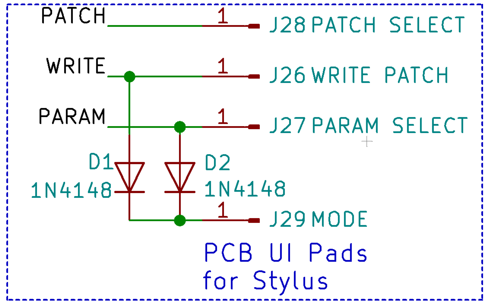
Now, if I could hit two pins at exactly the same time (say WRITE and PARAM), I could detect that in software. But if I just wired those two pins to the pad, it would hit both pins if I hit either of the original pads as well.
The obvious solution to that is to add two diodes going from those pins to the MODE pad that I want to trigger. Current can go to the MODE pin, but it can't come back up to the WRITE pin if the PARAM pad is touched, and vice versa. SMD Diodes are cheap, and PCB assembly houses usually have that kind of thing in their stock, so I'm not even worried about the price of these items.
The circuit for this is pretty simple:
![]()
I used a 1N4148 switching diode, which is pretty common in keyboards and such and is very good for this type of task. I still have a ton of them from when I was trying to build my own keyboards for the NanoEgg synthesizer project (I will get back to it eventually, I promise!)
So then, wiring it up:
The first thing to do is to disconnect the mode button pad from it's pin and from the pad for the key that needed to be remapped.
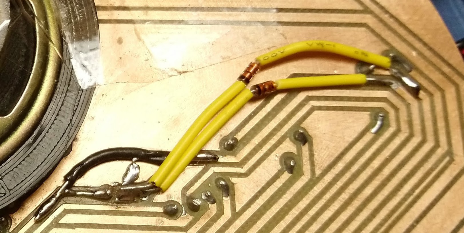
Then a bodge wire needed to be run to reconnect the keyboard pad to that pin again. That is in black in the picture below.
Then, two diodes need to be attached to the MODE pad (black line on that side for correct polarity, and the other end attached to the pins/pads for WRITE and PARAM. I put yellow insulation on the leads to keep it from shorting stuff out. It is easy to find such things on the floor if you never clean up in your workshop / home.
![]()
Here you can see the two diodes in yellow attached to traces going to their pins on the right, and the mode button on the left, and the wire rerouting the key's pad to the pin that was formerly for the mode button in black on the lower left.
Powered up in software and everything is worky! Yay!
How to do the software?
Just put an "if" statement before returning any key down and check for both pins together. If they are down, set the value to the mode button instead of either of those two pins. Standard debouncing applies.
So, there you go. A pretty basic hack that involves hardware and software, but saves a lot on money for a multiplexer. Obviously, one could use this technique to multiply pins to get more buttons, but at some point board real-estate, part and assembly costs come into play and you might be better off with a multiplexer or shift-register solution.
Pad multiplication with "charlieplexing"?
Another interesting possibility, similar to "charlieplexing" would be to move the stylus to a pin that can do input and output, and then use a diode on each pad to indicate whether it was sensitive to being an input or output. On some pins, the stylus would act to pull the pin, and the pin would be the input. One others, the pin would be the output, and you would detect it's touch on the stylus line. This does require one diode per key, and requires one additional pin for the stylus, but doubles the number of pads you could attach.
I'm not sure the "multiple downs per button" thing would work well here, since you have other pads reading current the other way that might be triggered when you change the line from input to output, but perhaps that wouldn't be a problem if the software isn't looking for that input at the time it is driven that way? I'm not sure; it bears further thought.
I know, I'll leave it as "and exercise for the reader" like they did in all of my old textbooks! Don't you just hate that? I always thought that was just the authors getting lazy. Which is exactly what I am going to do now...
-
New Intro Video!
10/08/2018 at 15:28 • 0 commentsI finally recorded the new intro video for Stylish! This one should fulfill all of the requirements for the Hackaday Prize (which the previous video did as well) and the "Tindie Project to Product Program".
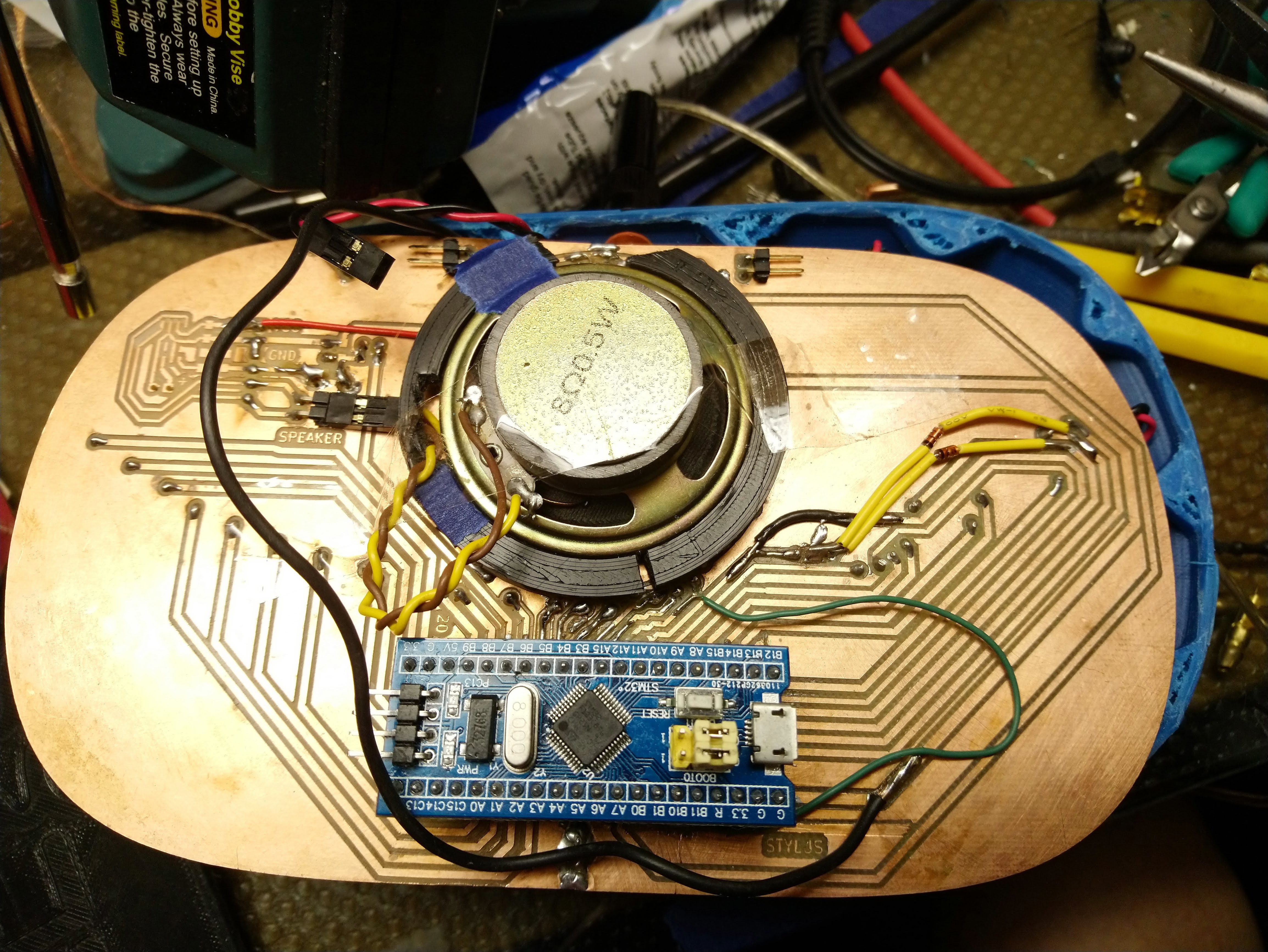
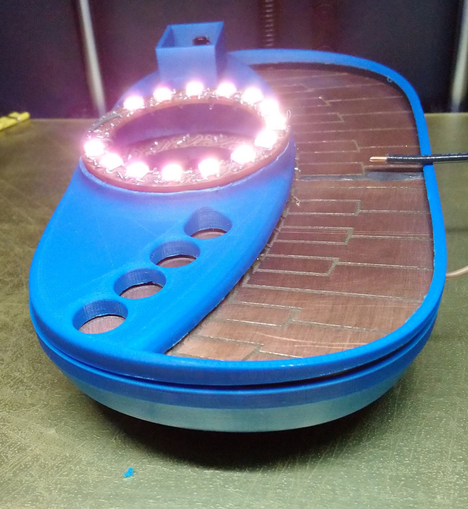
This video appears only as the result of a full night of hacking to get the thing to be presentable.First, the inside of the 3d printed case was Dremel'd out to give more room for the PCB so that the enclosure would have a better chance of actually closing.
Some holes were drilled in the bottom of the case so that the USB and debugging lines could get out. One of these cracked the plastic and left an oversized hole that I covered with blue tape for the show.
![]()
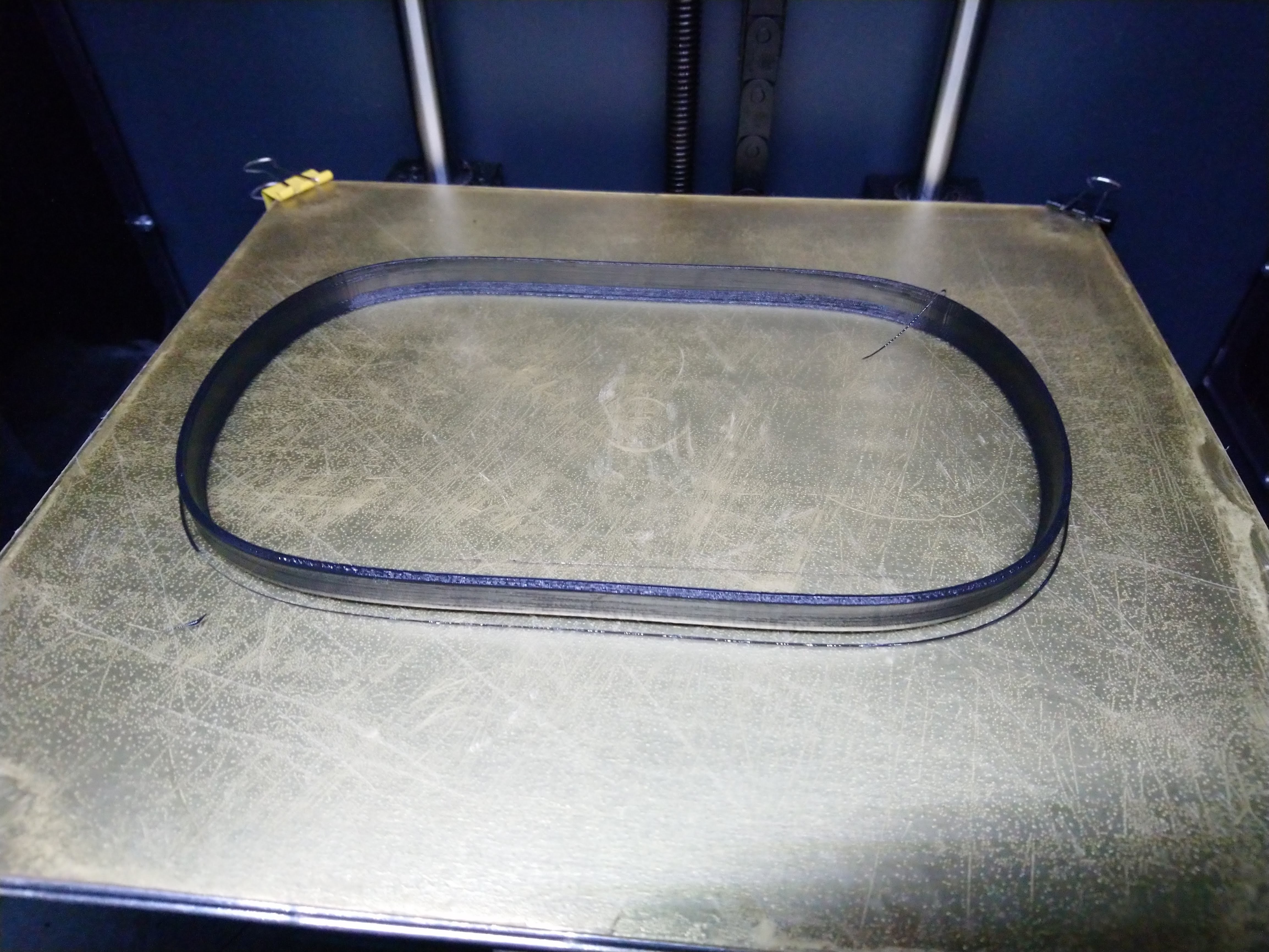
I was really having trouble getting the case to stay shut, so I designed a part to cover the seam, and printed it out of TPE (aka Ninja-flex) to cover the gap. It worked, but it didn't hold the thing together, so I had to add some clear tape to keep it all from falling apart. In the process of adding the tape, I lost the TPE ring, and so it didn't show up in the video. I found it immediately after uploading the video.
![]()
![]()
![]()
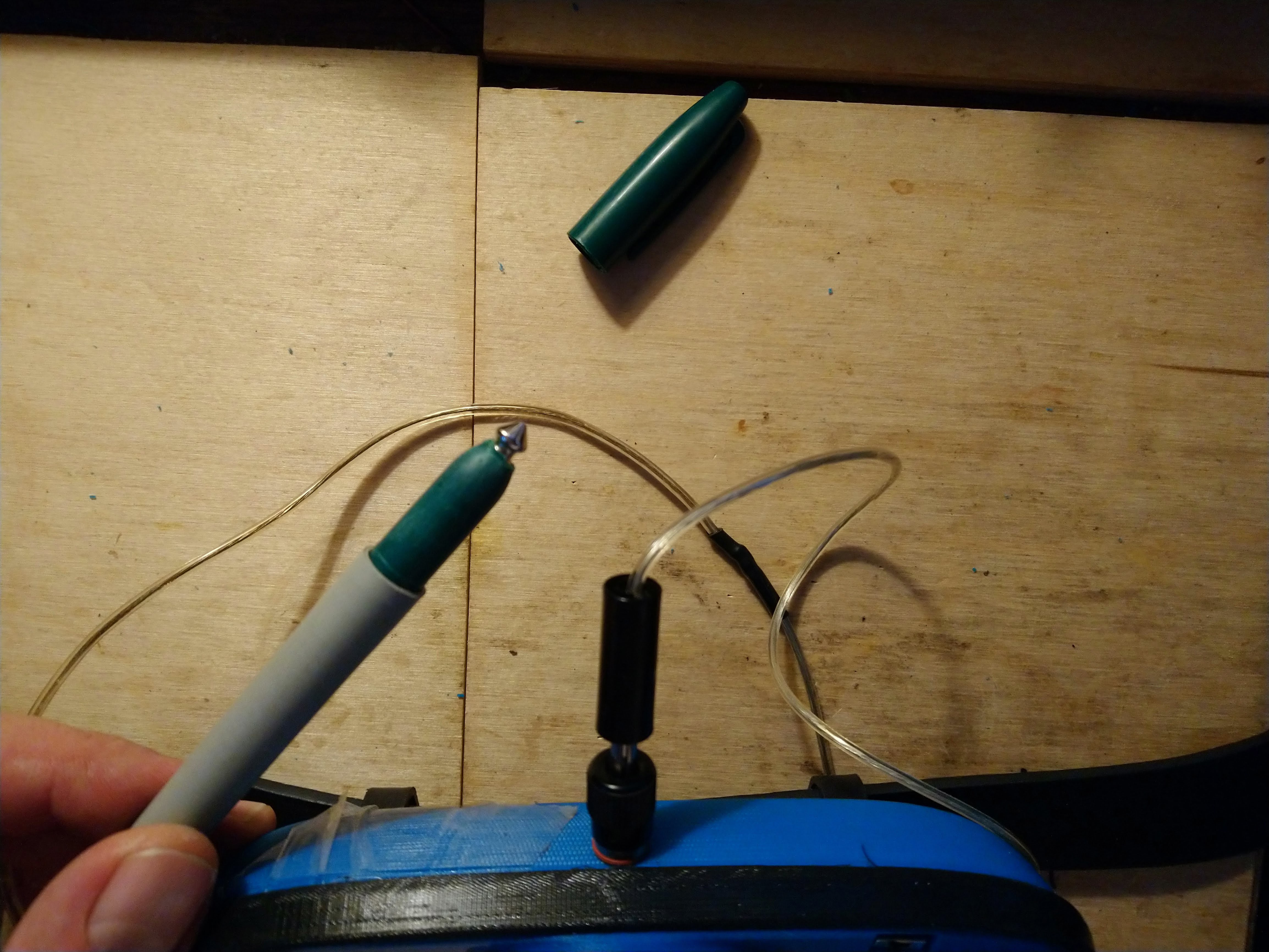
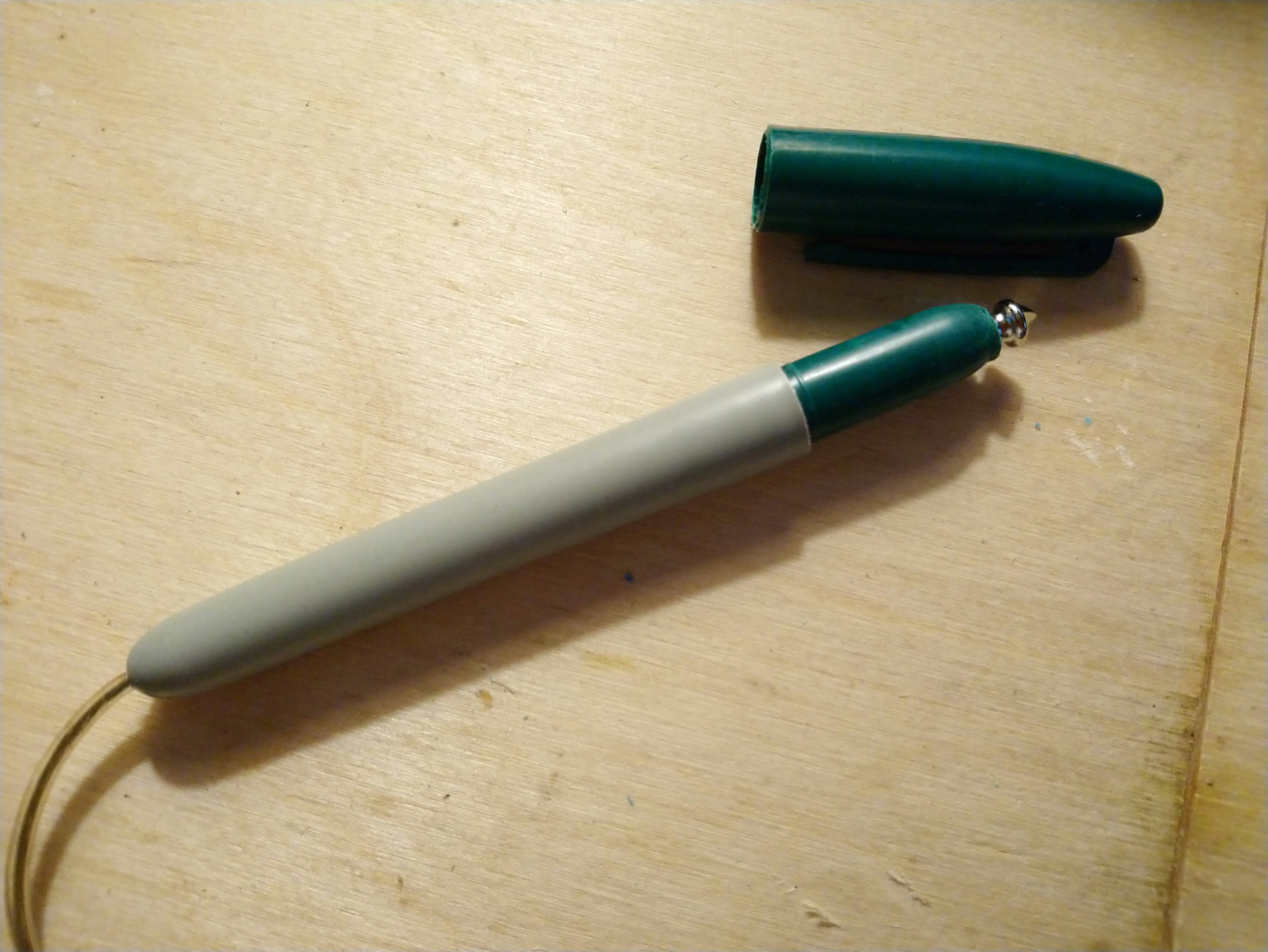
I made a new stylus by hollowing out an old permanent marker and adding a tip from a 1/4" to RCA adapter that had broken in half. I used the soldering iron to heat the tip and push it into the plastic, and then to smooth out the plastic afterwards. I soldered a foot long piece of stranded speaker wire to it, which was threaded through the pen body. The pen body and tip had all of the felt removed and once everything was installed I filled it with silicone RTV to seal things up and give it a little weight.
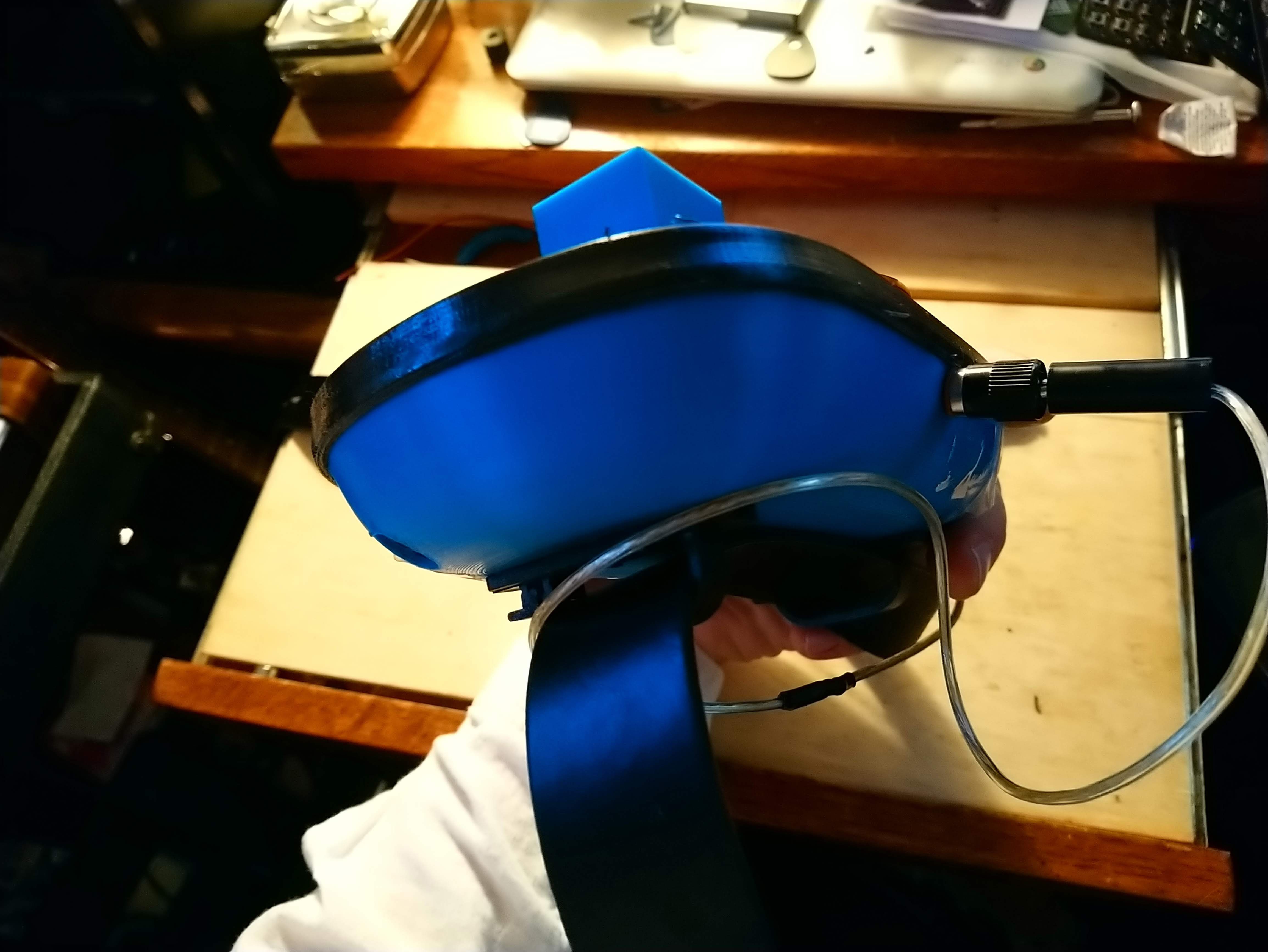
I dug around in my storage until I found an old fashioned banana plug and socket to attach to the case for the stylus to plug into, allowing the stylus to be removed. I am a 3rd generation electrical engineer, and have the accumulated junk^h^h^h^h technical wealth of that I have inherited from my late father and grandfather to dig through, so I can almost always find what I need if I look hard enough. I used the soldering iron to melt a hole through the case and screwed in the socket for the banana plug there, taking care to make sure the plug was not at such an angle as to cause the case to ride up. But then it was discovered that the back of the plug was hitting the speaker mount, so the back of the speaker mount was clipped off. That caused the speaker to immediately fall out, so I taped it in with some clear tape. I'm not proud... ya do what ya gots ta do!
Then, solder joints were repaired on the board to get the LEDs working again, fix a stuck key, and the new lead for the stylus, which was attached to the banana plug socket with a proper crimped wire contact and everything! Having fixed all of this, the holes for the USB and debugging weren't necessary any more, and I was able to attach the batteries.
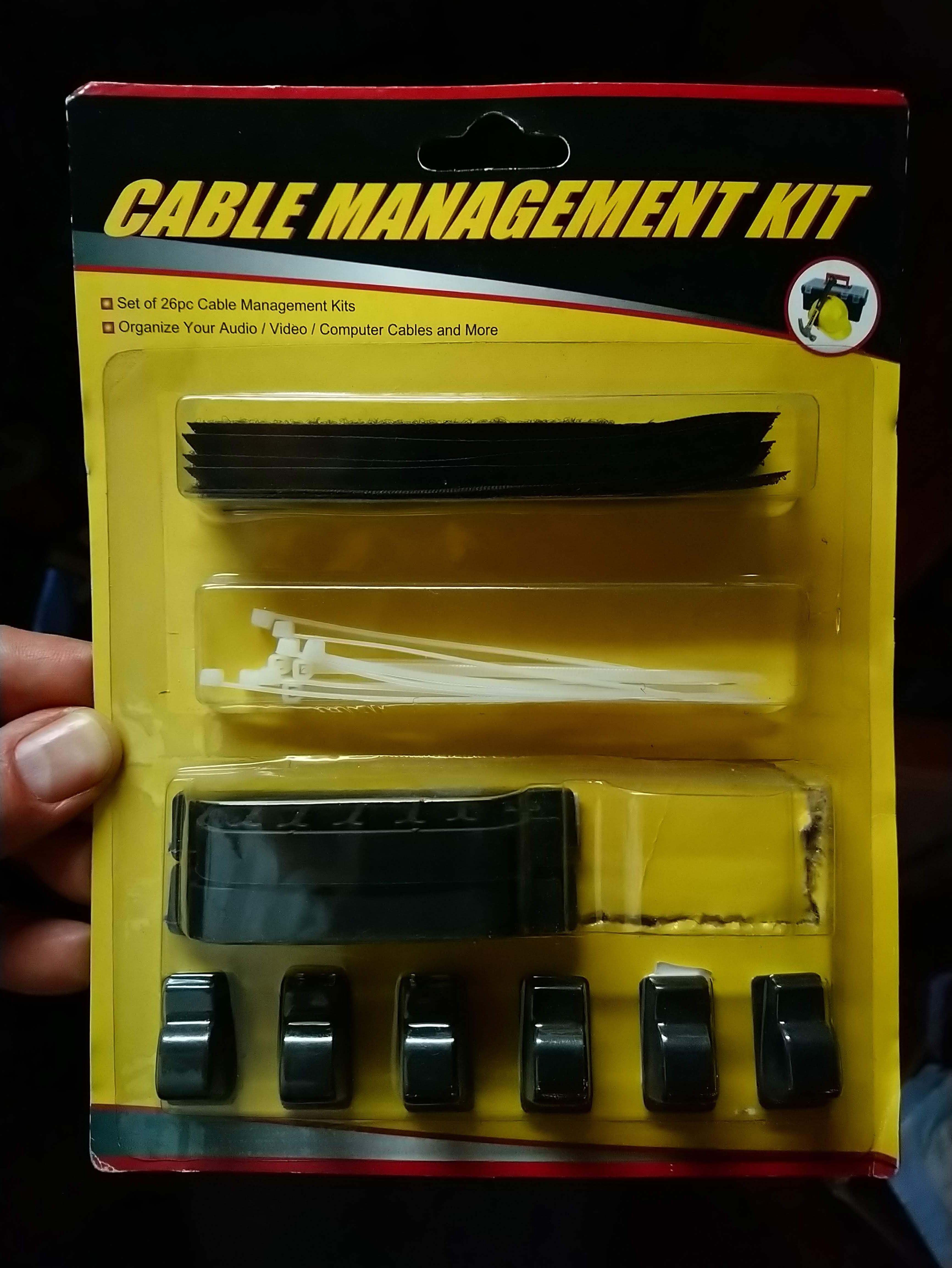
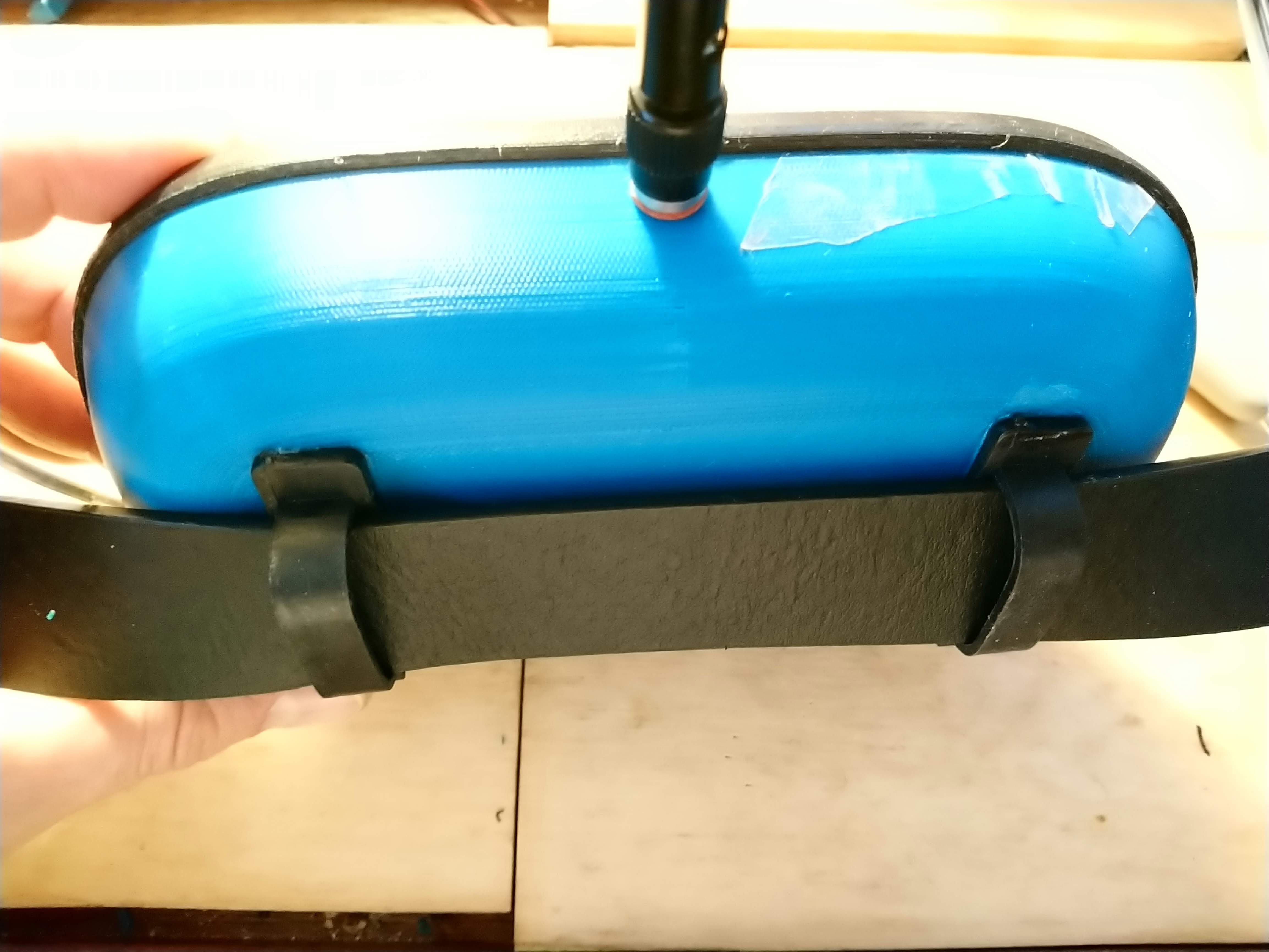
I knew I wasn't going to have the final belt mount ready, but I wanted to have something that would work, so I dug around and found the perfect thing!
![]() I clipped out the spacers for cables in the middle of the medium sized clips, and super-glue'd them to the back.
I clipped out the spacers for cables in the middle of the medium sized clips, and super-glue'd them to the back.![]()
![]() At this moment, I just realized that there is an issue with the video, and so I have to re-upload it. But a TON of progress was made tonight/this morning, even if it was mostly dog-and-pony stuff that won't be reused, it makes it easier to show the thing off.
At this moment, I just realized that there is an issue with the video, and so I have to re-upload it. But a TON of progress was made tonight/this morning, even if it was mostly dog-and-pony stuff that won't be reused, it makes it easier to show the thing off.![]()
-
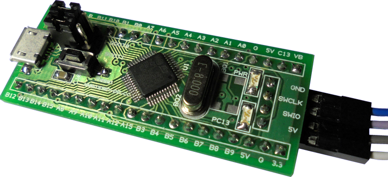
Found an open-source version of the Blue Pill microcontroller board.... sorta
10/07/2018 at 23:51 • 2 comments![]()
While perusing the other Hackaday Prize entries for this year, I noticed that there is an open source version of the blue-pill board that I'm using for this project! The "green pill" is by open-plc.com.
I followed the links over to GitHub, where I discovered that, while they published PDFs and Gerbers, the original board and schematic files from design software were not in it. So I can't make a nice 3d render of the board, or add modifications, or incorporate it into my own designs or anything.
So "open", but no usable "source". C'est la vie.
I sent a message asking for the sources to be posted. Maybe they will do it?
-
Storing Patch Data in Flash
10/07/2018 at 14:45 • 0 commentsI hadn't really looked into the amount of EEPROM "save" memory that the STM32F103 series chips had, but I assumed that it had some, and that it would be comparable to the AVR chips, which have ~1k in Arduino.
I was wrong.
It has some storage for registers for power-down sleep conditions, but that's only around 20 bytes. One patch on this system is going to be 16 bytes, fully packed, so that really doesn't help.
So I looked into whether it would be possible for my program which is in Flash memory to actually save data to Flash.
It does appear to be possible!
I found a fine article here on how to do it.
I haven't tried it yet, but I'll be updating this log entry as soon as I do!
-
3d Printed Enclosure: First Draft Issues
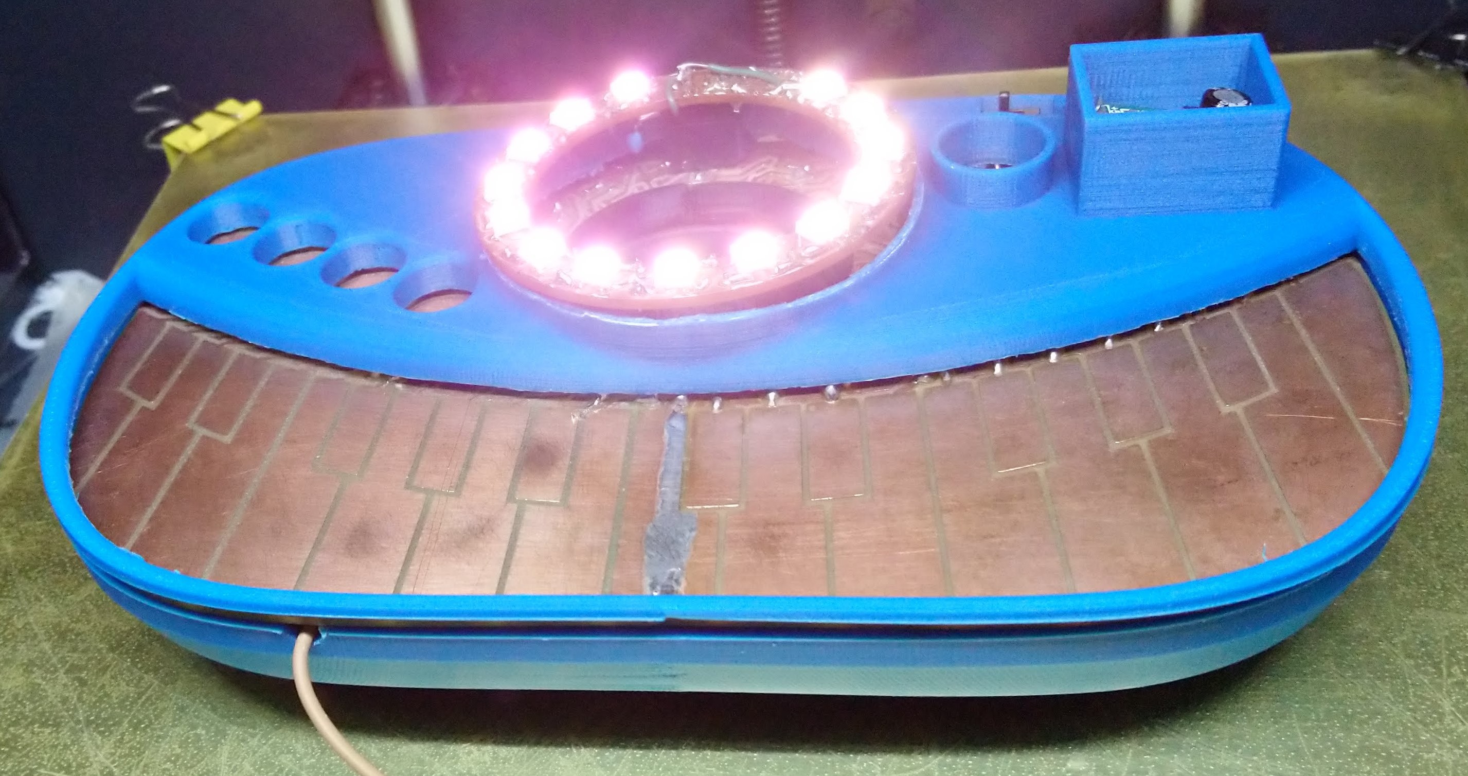
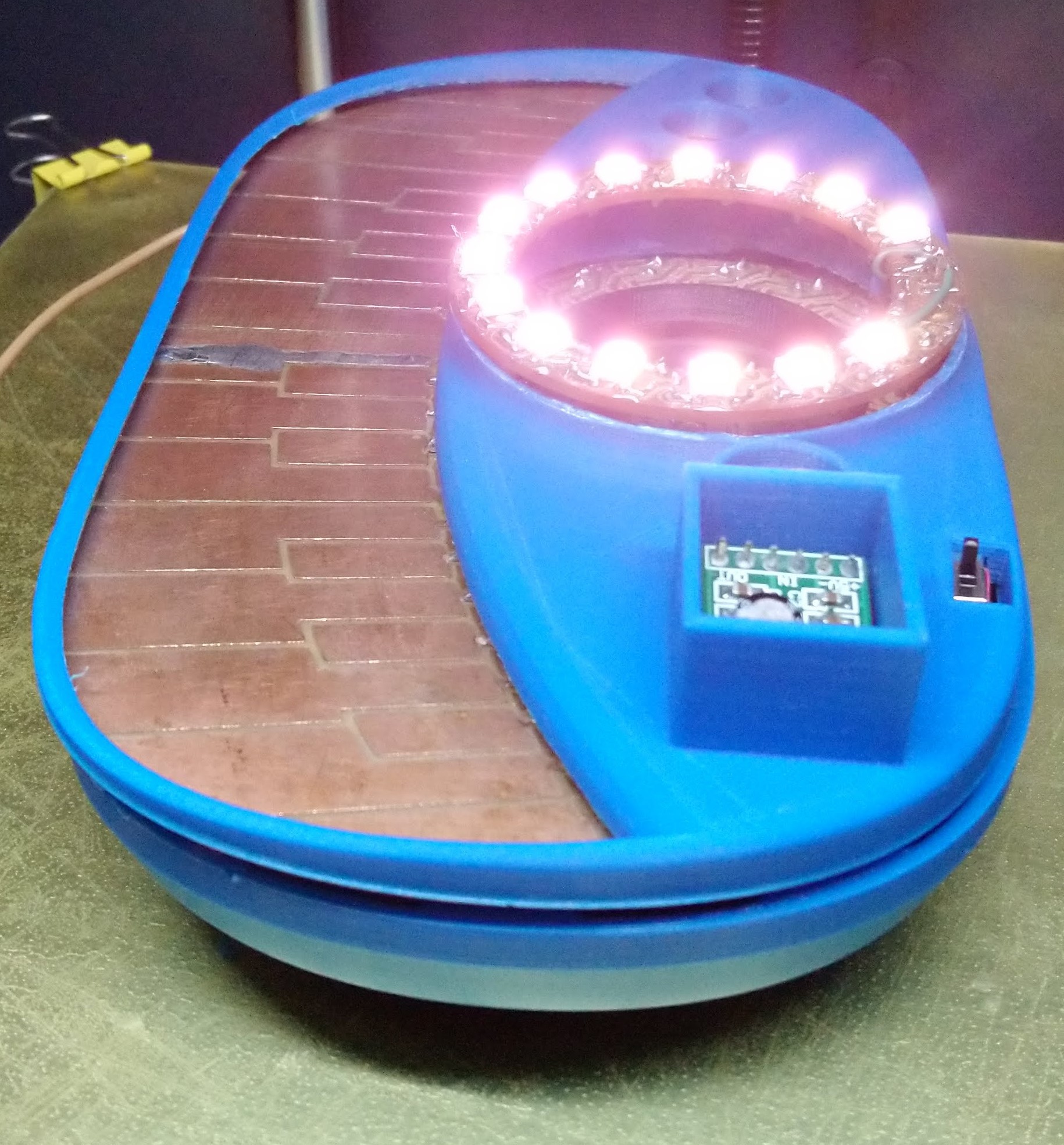
10/07/2018 at 14:05 • 0 comments![]() So, 22 hours later, I've got my 1st draft 3d printed enclosure! I knew it was going to have some problems, and I wasn't disappointed!
So, 22 hours later, I've got my 1st draft 3d printed enclosure! I knew it was going to have some problems, and I wasn't disappointed!![]()
As it came off the 3d printer!
![]()
But if you don't look too closely, it does look pretty!![]()
![]()
The Tindie contest requirements say you should show your project inside and out, so here it is!
![]()
![]()
It... doesn't fit together as well as I'd like, I had to chop, chop, chop away a lot of stuff to get around all of the bodge wires and lumps of solder, etc. and even then it doesn't go together very well.
When assembled with batteries installed, it works very strangely. The LED ring will either light dim red, or full bright white when the power switch is on. It will play, but it won't light up correctly. It works fine when USB or programming adaptor are installed. It ran fine on batteries for yesterday's case, so I can only imagine that the manhandling to put it in the case is disturbing some delicate connection somewhere.
Anyway, things learned:
- There should be a groove in the bottom part for the board to fit in.
- There should be a much thicker edge around the board.
- The groove in the top part that the board fits in is really hard to get support material out of.
- The hole for the LED ring is way too small, and the tube is too tall.
- The power switch hole isn't wide enough.
- There should really be some holes or groves for the stylus, USB, and debugging connections.
- There should be some sort of mount for the battery.
- The speaker mounting ring really doesn't fit in the hole when printing, and really had to be chisled out.
- he solder vias at the top of the keyboard cause things to ride up.
I thought I had to have another video done by 7am, but it turns out to be 7am on Monday. And it's Sunday. Who knew?
So I get to sleep before I try to make another video. Yay!
-
Gerbers and 3d model STL files added to the GitHub
10/07/2018 at 10:26 • 0 commentsI noticed that there was also a Tindie contest associated with the Hackaday Prize contest, and they require that you share the Gerbers for your project, so I added them to the GitHub. I also added the STL files for the case (that I am currently still 3d printing). Mind you, all of these items are in heavy development, and so might not be quite up-to-date, or if they are up to date, they might not have been tested yet. So, be wary before trying to build it!
-
State Machine Design
10/07/2018 at 04:34 • 0 commentsI took a little time to work up a design of the state machine for patch changes and parameter changes. This design covers what happens when you press the buttons, and how the LED ring updates to reflect the result.
I played around with trying to write this with a state machine tool so that there would be a lovely picture, but found that the boxes were cumbersome to fit ideas into, and it was annoying to work with the arrows. Spatially, it didn't really work out. So, outline form it is. The format is:
- STATE_NAME: Description : Longer Explanation
- Thing that happens when running this state ~or~
- Keyboard Event
- Things that happen when this Keyboard Event occurs (state change only if explicitly stated)
Hopefully this makes some sort of sense to people who aren't me.
I've got the whole lovely thing in a Google Doc, but I'll reproduce it here:
Stylish! Trucker Belt Buckle Synthesizer: State Machine Design- PLAY: Keyboard Play Mode
- On Key Press
- Last selected note is saved
- Note On Trigger
- On Key Release
- Note Off Trigger
- On Button Press:
- PATCH_SELECT_WAIT
- PATCH_WRITE_WAIT
- PARAMETER_SELECT_WAIT
- MODE_CHANGE_WAIT
- On Key Press
- PATCH_SELECT_WAIT :Patch Change: Waiting for Patch Selection.
- Flash Ring Green
- Block till stylus up
- On Key Press
- Select tentative patch from key number
- Play new patch using last key selected or middle C if none
- On Patch Change Button
- Tentative patch becomes current patch
- Return to PLAY mode.
- Other Button Press
- Go to that button’s WAIT mode
- PATCH_WRITE_WAIT: Patch Write: Waiting for Patch Selection
- Flash Ring Red
- Block til stylus up
- On Key Press
- Select overwrite patch from key number
- Play new patch using last key selected or middle C if none
- On Write Button
- Copy current patch data over selected overwrite patch
- Current patch number = overwrite patch number
- Return to PLAY mode with original patch data
- Other Button Press
- This is an abort of writing
- Patch returns to modified data from before WRITE hit
- Go to that button’s WAIT mode
- PARAMETER_SELECT_WAIT: Parameter Change: Waiting For Parameter Selection
- Flash Ring Blue
- Block til stylus up
- On Key Press
- Select value from key number
- VALUE_CHANGE_WAIT
- On Value Button
- Return to Play Mode
- Other Button Press
- Go to that button’s WAIT mode
- VALUE_CHANGE_WAIT: Value Change: Waiting for value
- Ring Flashes Blue, with the current parameter number’s LED with Green Chanel On (not Flashing) and current value of that parameter with RED channel On (not flashing)
- Block til stylus up
- On Key Press
- Parameter value is changed to value from key
- Play current sound using last key selected or middle C if none
- On Value Button press
- Return to Play Mode
- On Other Button press
- Go to that button’s WAIT mode
- MODE_CHANGE_WAIT: Mode Change: Waiting for Mode Selection
- Flash Ring Dim Yellow
- To Be Continued… Might work like value change for some values, but other values toggle instantaneously, so maybe it’s quick to change animation mode, but you have a two step to handle animation speed, tempo change, etc. Sequencer mode or drum loop drops you into a whole new state machine.
This much should get us to functional synthesizer
- STATE_NAME: Description : Longer Explanation
-
A first draft video!
10/06/2018 at 14:43 • 0 commentsRather than sleep, I decided to get at least one pass made on the video required for the Hackaday Prize entry. HERE IT IS!
It isn't perfect by any means, but I think it get the point across.In this test video, for the first time, I perform a complete song with "Stylish!"
This is the first working prototype of Stylish! and there is still a LOT of work to be done before it can be made available to the general public.
Unfortunately, the LED ring kinda died in the middle of the second test run for this song, so it isn't spinning and flashing as much as I'd like. Also, some of the great intended features like sound editing, multiple patches, and LED animations just haven't been implemented yet. The 2nd board is gonna be a huge improvement over this one!
I can't say that I did a perfect job playing the song, either. The stylus is currently just a tiny length of stiff copper wire... perhaps a little too tiny. Between that and the bandaid on my finger, it was difficult to keep it from sliding up. More things to fix in the future.
Anyway, I hope you like the demo. Maybe I'll have a better one tomorrow!
-
Designed a 1st draft of a Case
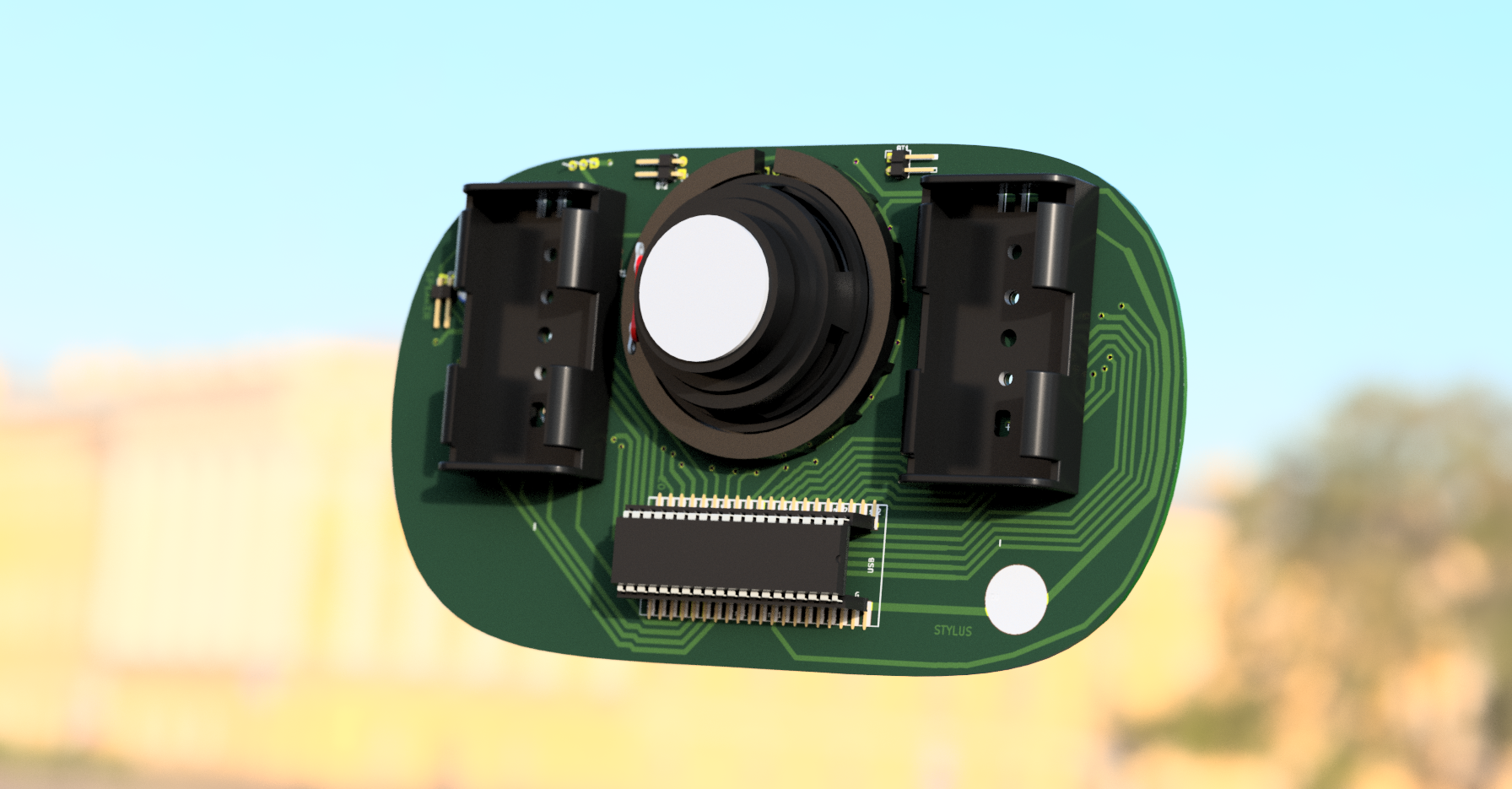
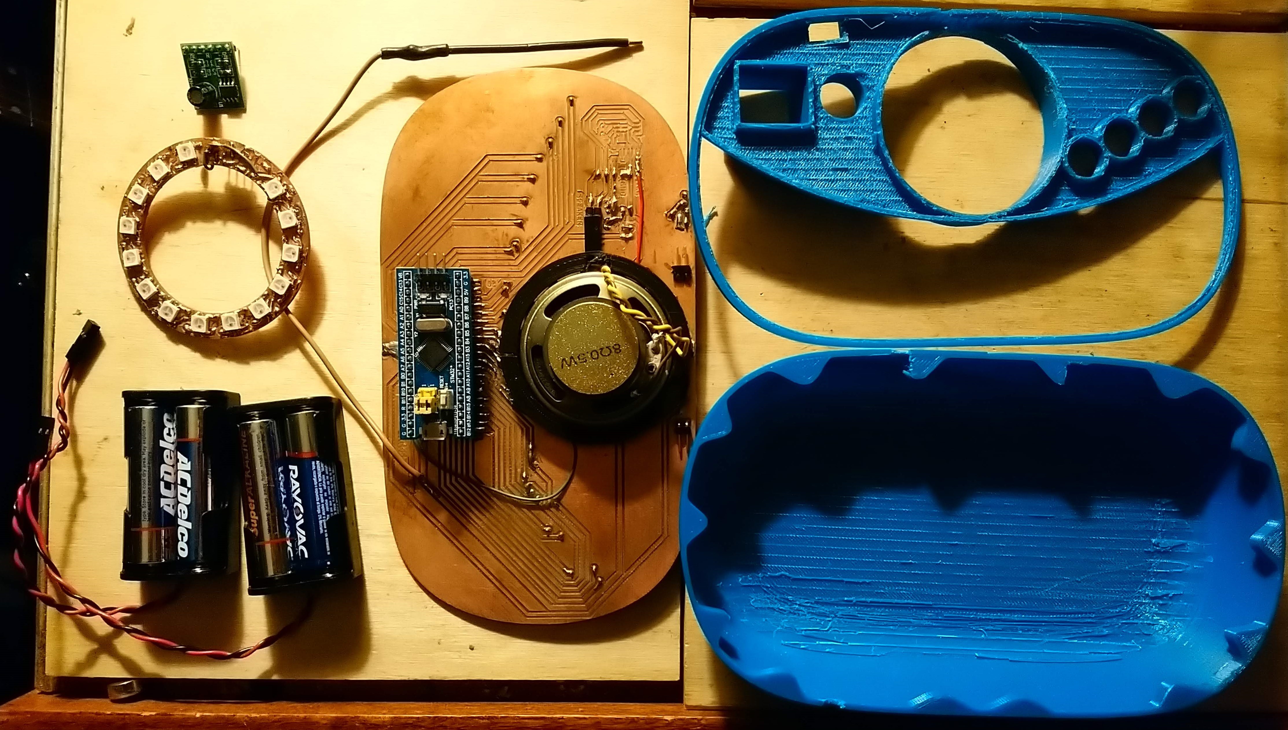
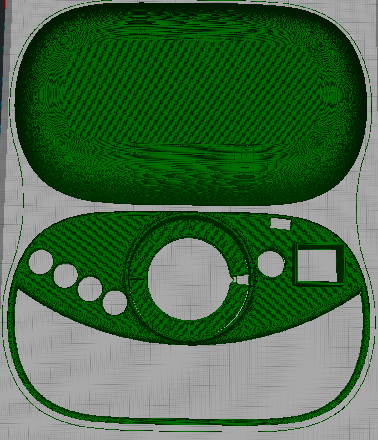
10/06/2018 at 13:39 • 0 comments![]()
For various reasons, instead of recording the video today like I was supposed to, I fixed all of the 3d models that KiCAD needed to render the PCB, and then build a 1st draft model of a case around them.
Originally, I was just gonna prep the board models that were already in fine shape to send to a friend who was going to work on the case.
KiCAD can save two types of 3d model:
- A VRML file that looks great, but is useless in solid body modeling programs like Autodesk Fusion 360.
- A STEP file that is missing all of the circuit traces and vias, as well as any components that didn't use a STEP file for their model, but works great in Fusion.
I worked hard to locate STEP files for all of the missing models, and then take renders of the board out of KiCAD with no models on them so that I could reattach it by hand to the STEP file in Fusion, which will not load textures on anything it didn't make, no way, no how!
I could swear I changed some of those parts 3 or 4 times before I got the STEP files to stick. Was I hitting "Cancel" accidentally?
In the process of doing this, I finally decided to make some holes in the board for mounting the battery holders, which meant shifting some traces around.
And the speaker mounting ring I did the other day? Thrown out and redone.
This case does actually have to accommodate the current PCB, which means leaving lots of extra space for daughterboards to stick out, which is why this case has some unsightly tubes sticking out of the front. That will go away when everything is SMD components.
This is probably a bunch of wasted effort because I'm gonna have to redo a bunch of this stuff. But I wanted a case for shooting the video. Which will probably take over 24 hours to print, which suggests that it will probably fail in the middle of the print job, while I'm sleeping, and burn the house down.
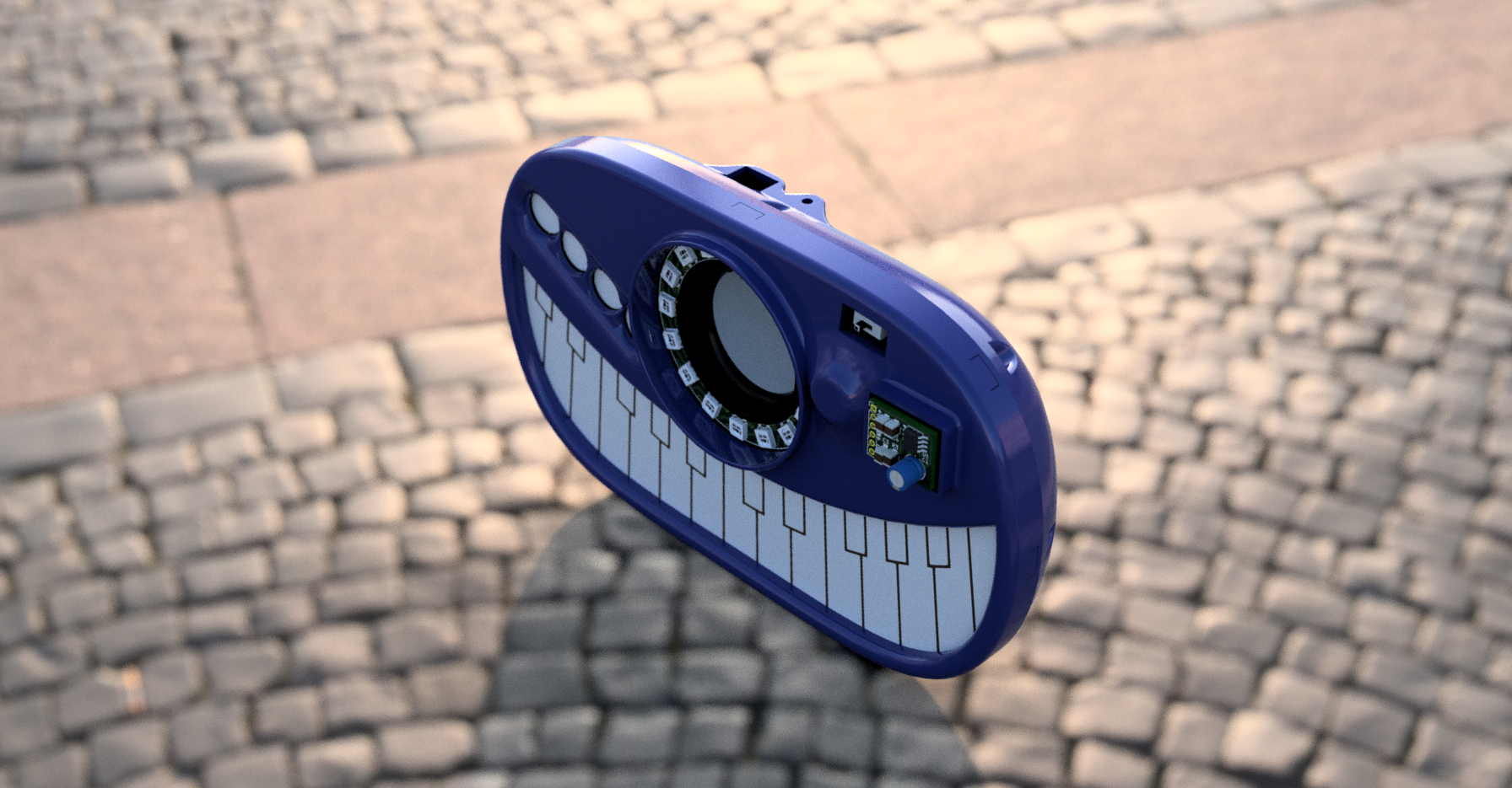
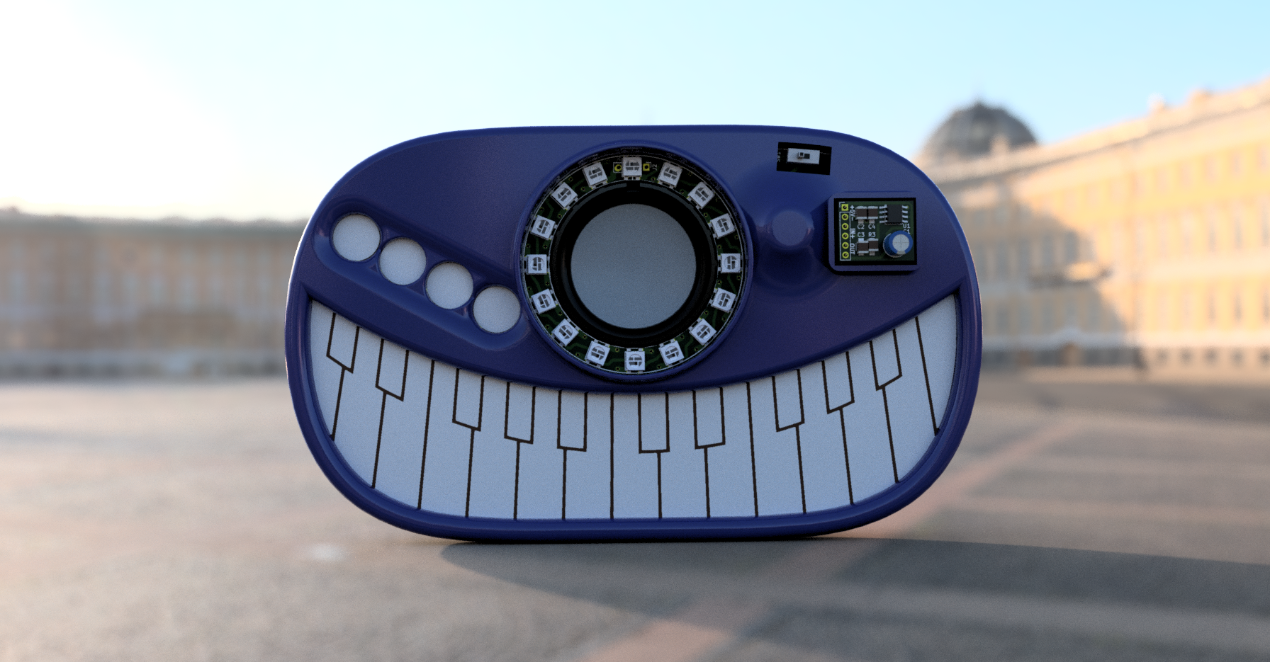
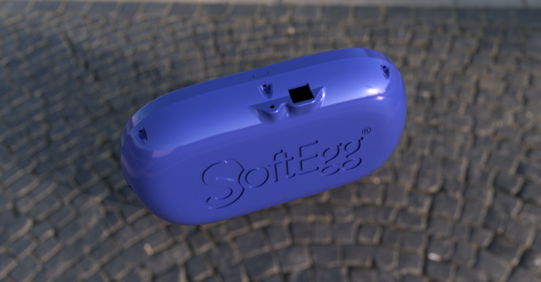
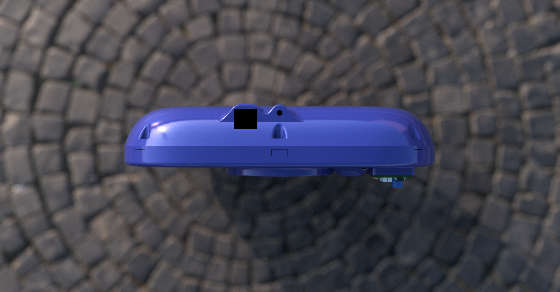
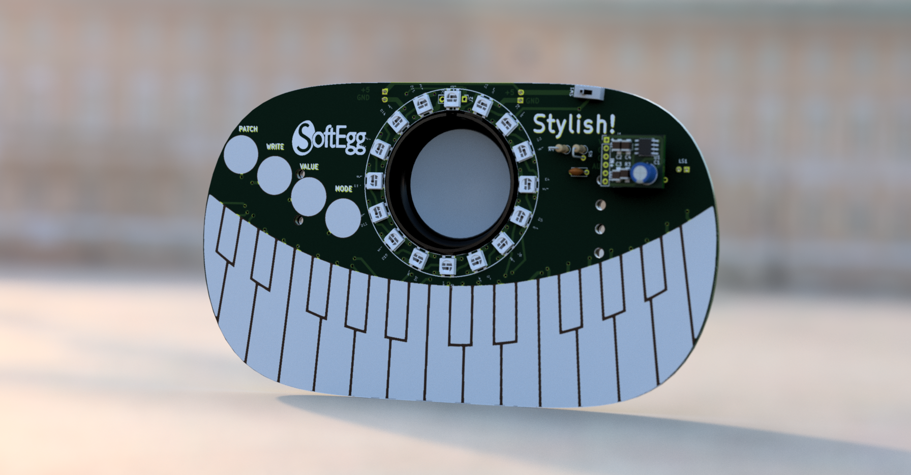
But hey, here is a fancy purple case on "Stylish!", floating in front of the Winter Palace in Saint Petersburg.
![]()
As far as the design goes, it's getting there. I figure a belt buckle has to be kinda round so it does't poke you and hurt when you wear it.
I was going for a "Dr. Teeth" style smile for the keybed, and the speaker is supposed to be like a giant cyclops eye (although I don't think the real speaker will be white like this one.)
The row of "button" pads on the left was more for function than for looks, and the giant tubes sticking out on the right were mostly design shortcuts to get the thing done in a way that works with the daughterboards of the prototype hardware... they will go away in the final.
Honestly, while the PCB has been an honest try, the plastic is just the quickest placeholder design I could do that didn't look awful.
I was proud of how I managed to round the back without having to create infinite planes and draw loft curves. I made an extrusion with a bit of a draft angle, put a huge filet on it, and then told fusion to hollow it out. I then cut open the hollow with another extrude. The front was done in several layers, with a bit of chopping off after. Unfortunately, it didn't like combining the layers, and so it wouldn't let me filet across the place where they join, but I did what I could.
Here it is laid out for printing in Cura. I had to really fight it to make it let me put the speaker ring in the middle of the hole for the LED ring so that I could print it all at once.
![]()
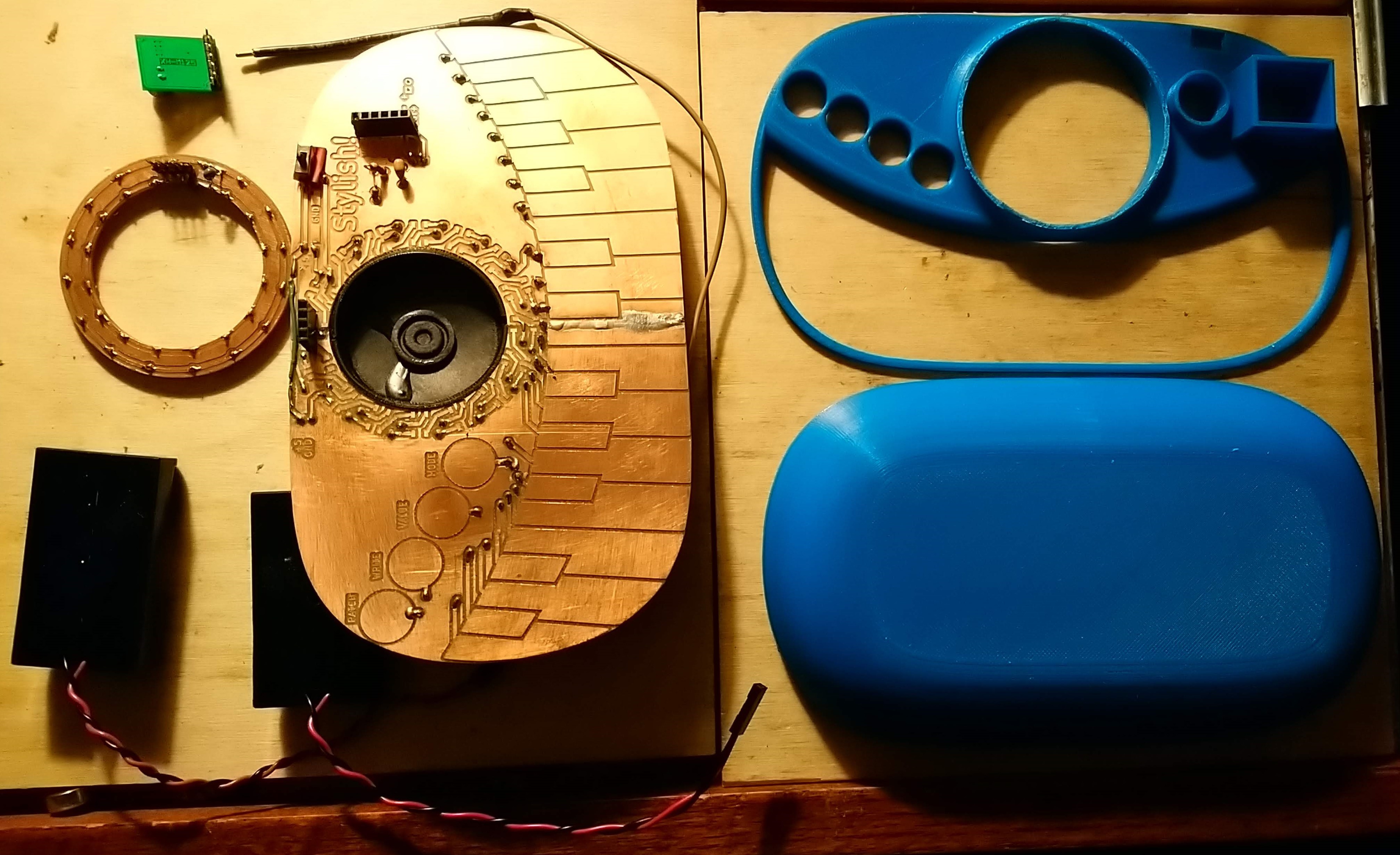
And what of my PCB models that are nicer than they really have any right to be? Here they are!
![]() I'm probably the only one in the world who has bothered to reverse engineer and produce a complete 3d model of that crappy little amplifier board from AliExpress. I'm not OCD at all!
I'm probably the only one in the world who has bothered to reverse engineer and produce a complete 3d model of that crappy little amplifier board from AliExpress. I'm not OCD at all!![]()
I really wanted to make a model for the STM32 "blue pill" board, but I'm so very OCD that I didn't do it because if I did, I'd actually have to actually accurately reproduce the whole board in KiCAD, and that could take weeks. So even though I could have slapped a texture on a rectangle of the appropriate shape and called it done, I didn't do that. I just put a standard 40 pin DIP on there. I don't know whether that is an accomplishment in fighting back OCD, or being lazy.
Anyway, the thing is in the 3d printer, printing. It's been at it for about 45 minutes, and is only 4.3% done, so I don't expect anything for at least 17 hours...
But maybe I'll make a video soon!
After I sleep.
Instead of going to the halloween party at Mountie Makerspace. Meh.
I hate deadlines.
Stylish!
A most stylish wearable music synthesizer! A real stylus based monophonic music synthesizer built into a giant trucker belt buckle!

 I clipped out the spacers for cables in the middle of the medium sized clips, and super-glue'd them to the back.
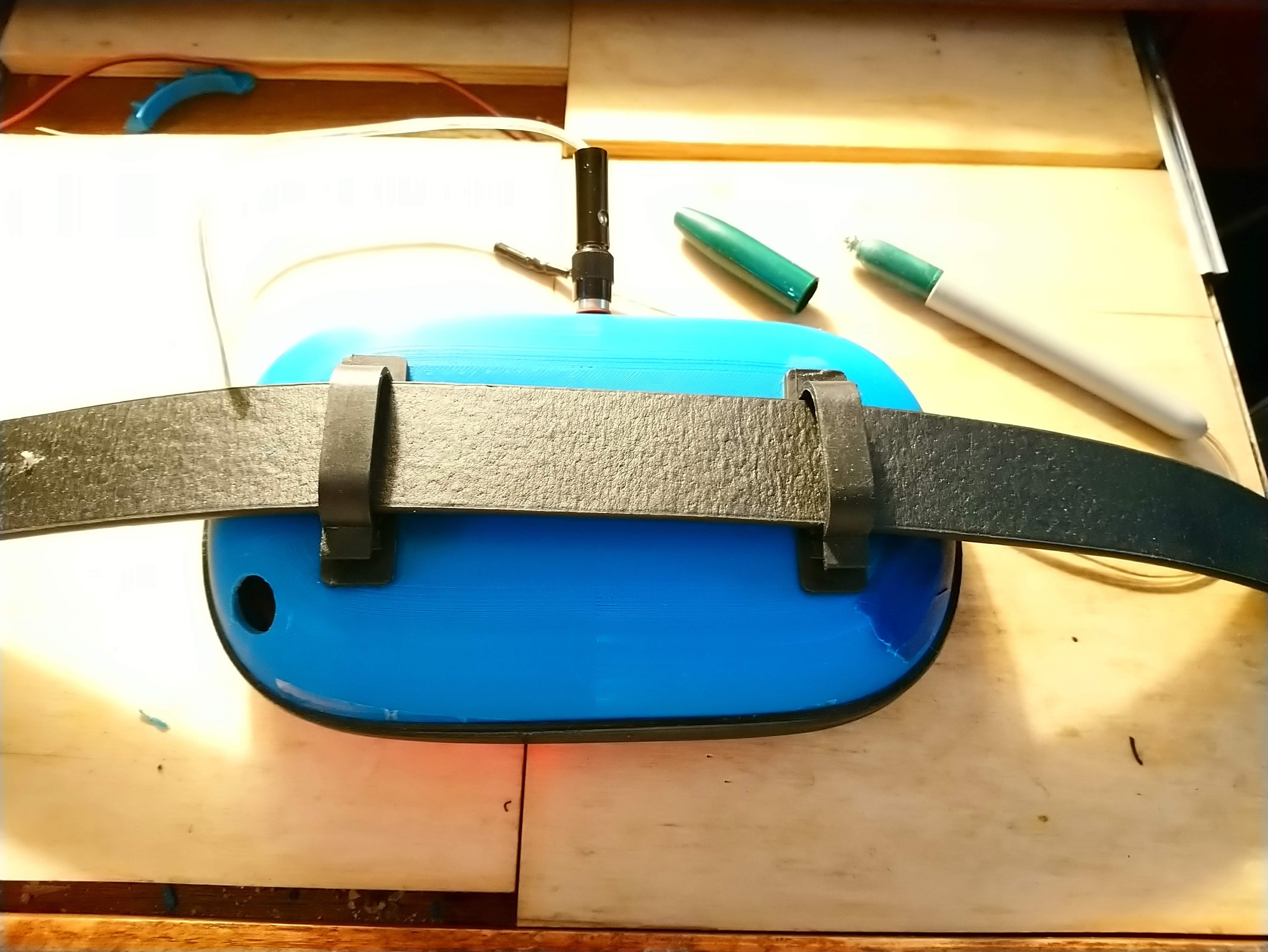
 At this moment, I just realized that there is an issue with the video, and so I have to re-upload it. But a TON of progress was made tonight/this morning, even if it was mostly dog-and-pony stuff that won't be reused, it makes it easier to show the thing off.
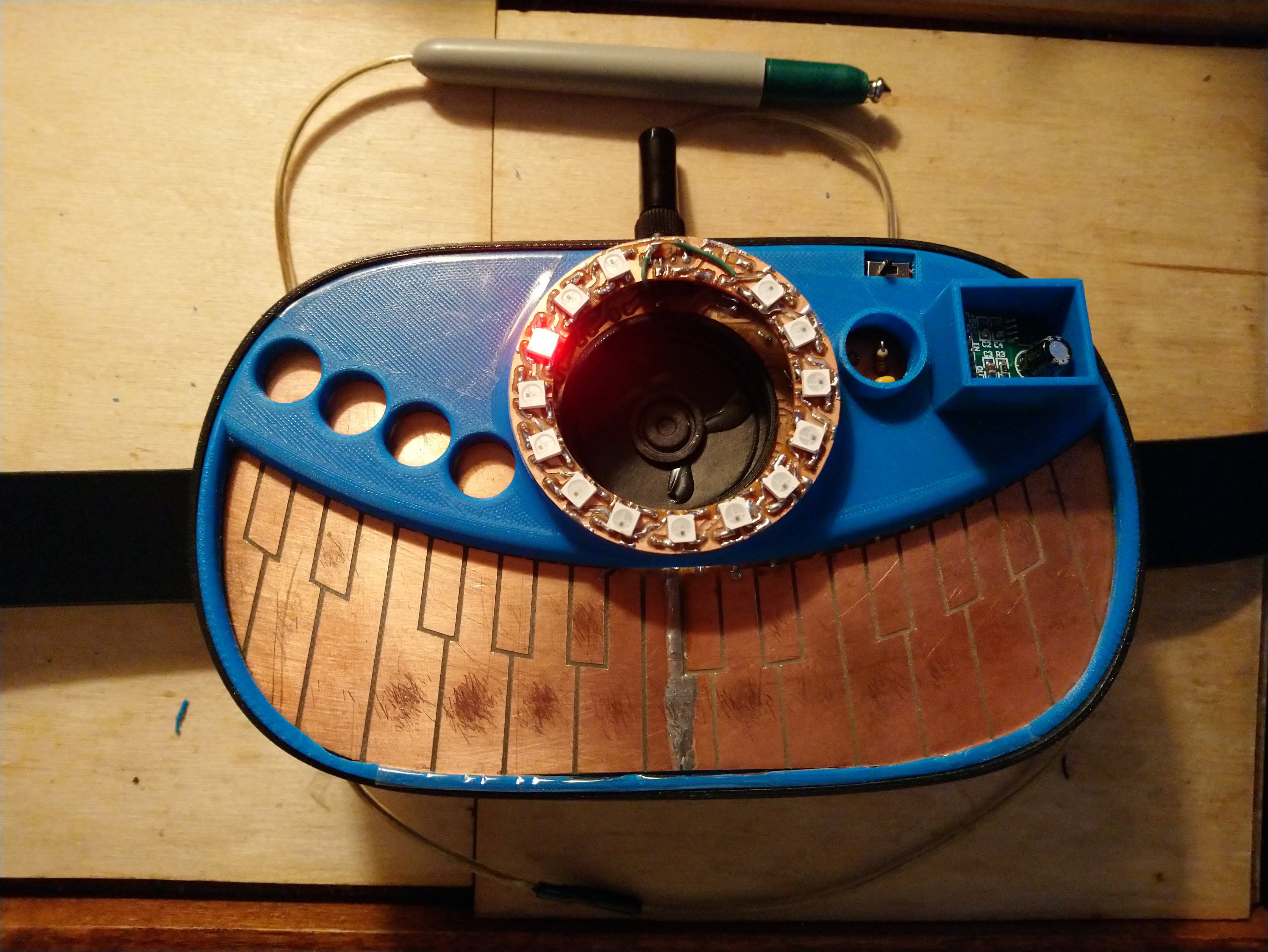
 So, 22 hours later, I've got my 1st draft 3d printed enclosure! I knew it was going to have some problems, and I wasn't disappointed!


 I'm probably the only one in the world who has bothered to reverse engineer and produce a complete 3d model of that crappy little amplifier board from AliExpress. I'm not OCD at all!