 JK
JK-
1Housing
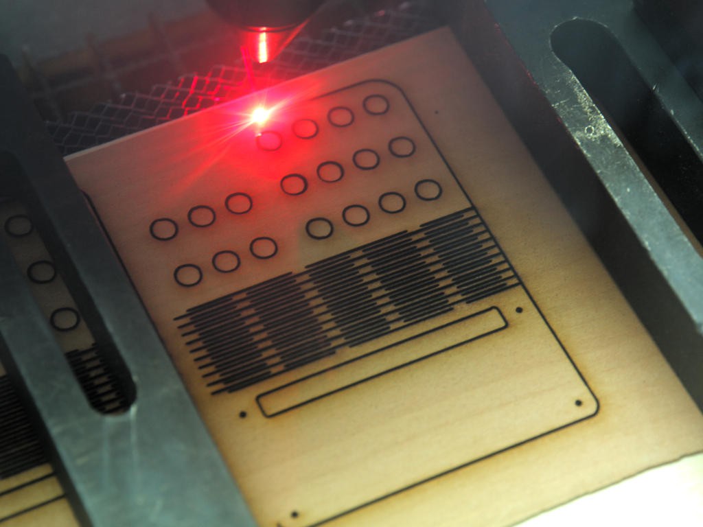
In this example I used LASER-cut plywood with a veneer layer and bend cuts.
![]() For this housing I used 2-k-epoxy-glue for the LEDs and wood-glue to 'freeze' the bend cuts.
For this housing I used 2-k-epoxy-glue for the LEDs and wood-glue to 'freeze' the bend cuts.![]() Feel free to use any kind of material and technique for your housing.
Feel free to use any kind of material and technique for your housing. -
2Layout
The BCD coding uses 4 LEDs for the second digit and 3 LEDs for the first digit. In the 12-hour configuration. The hours are also displayed with 4 LEDs.
For 24-hour configuration the hours are also used 2 digits as minutes/seconds.
The layout can be horizontal (like this example) or vertical. The second digit LEDs can be aligned in a row or between the first digit LEDs. Feel free to experiment with your design.
Example A:
![]()
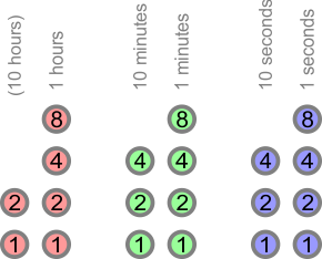
Example B:
![]()
Example C:
![]()
![]()
-
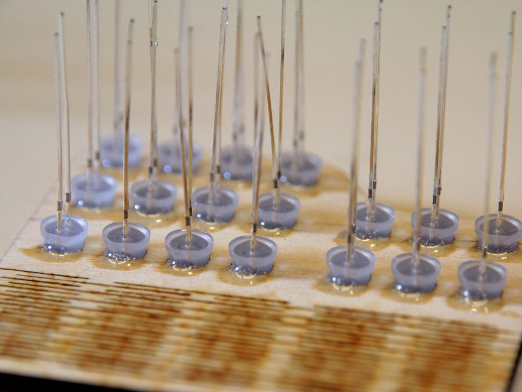
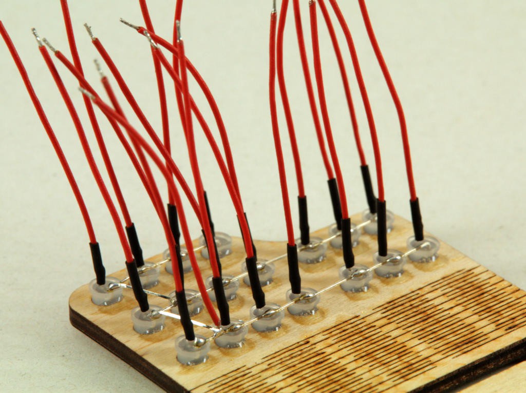
3LEDs
Solder all cathodes (short leg, minus) of the LEDs together and connect them to GND. Solder the anodes (long leg, plus) of the LEDs to the corresponding pin on the RPi (see pinout). Resistors are not necessary.
![]()
-
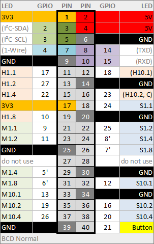
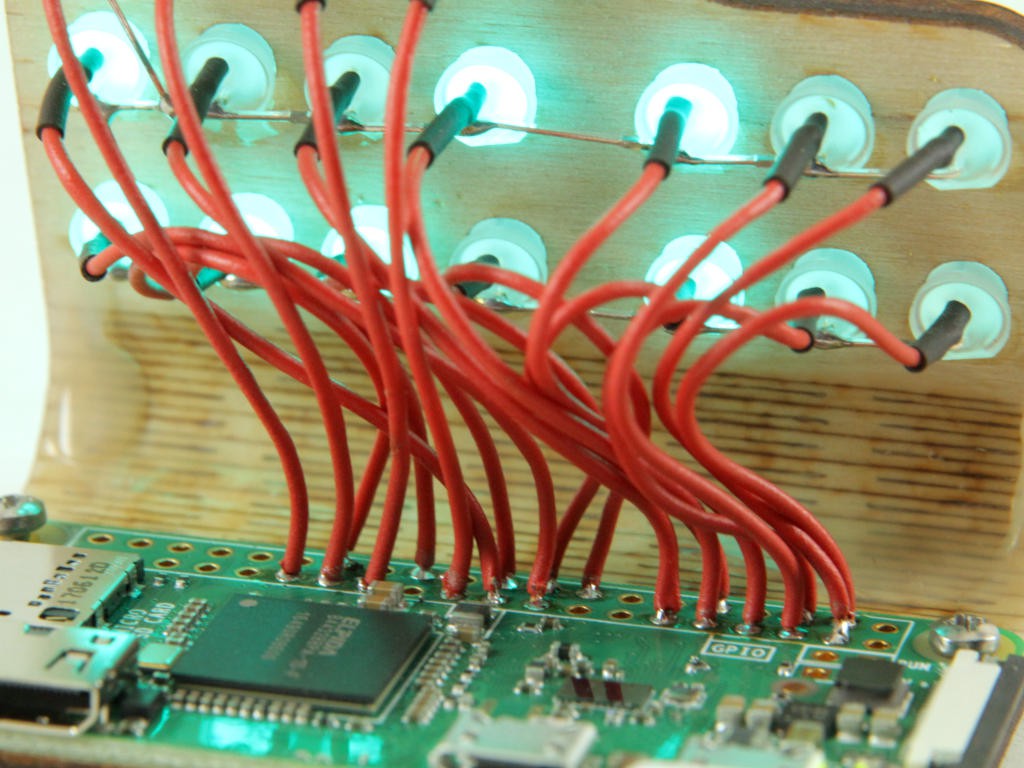
4RPi Pinout
Pins 11 to 38 should be used for the clock LEDs.
Pins 39 to 40 is reserved for an option button.
Pins 1 to 10 are free for optional I²C devices, 1-Wire devices, serial adapter and other GPIO stuff.
Default Pinout:
![]()
Note: The LED to GPIO mapping can be easily changed in source code
![]()
-
5RPi Software Configuration
See detail description on GitHub Wiki
In short:
- Setup network/WiFi
- Disable SPI
- Install linux packages 'python3' and 'pigpio'
- Install python modules 'argparse' and 'pigpio'
- Enable deamon 'pigpiod'
- Download source from GitHub
- Autostart '~/piClock/bcd.py' at boot time
Linux experts will configure the RPi in no-time. Less experienced users (like me) needed more time for configuring than for wood-working and soldering.
-
6Step 6
BCD-Clock with RPi zero W
Simple LED BCD-Clock with a Raspberry Pi Zero W using Python and pigpio-lib
 For this housing I used 2-k-epoxy-glue for the LEDs and wood-glue to 'freeze' the bend cuts.
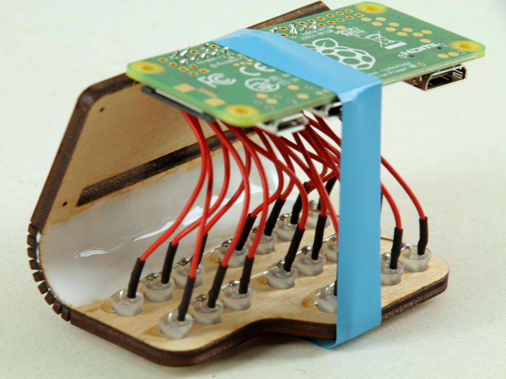 Feel free to use any kind of material and technique for your housing.
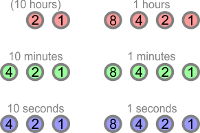

Discussions
Become a Hackaday.io Member
Create an account to leave a comment. Already have an account? Log In.