 Thomas
Digital voltmeters are popular: they give the user the feeling of getting an accurate measurement. However, accuracy has a price (e.g components with stable parameters, temperature compensation, reference voltage...). They say "you get what you pay for".
Different sellers at Chinese outlets offer LM2596 DC/DC converters with a voltmeter that, depending on a key press, shows the input or the output voltage. The price for such a module starts at $1.55 (including shipping halfway around the globe).
This has a smell of cheap µC although there is no ICP connector to be seen. I ordered one out of curiosity.

Of course, the only place where a µC could be hidden is below the display. I put it aside because removing it with a suction pump didn't work. Yesterday I played with a LED torch and in the bright light I spotted a TSSOP 20 package. Bingo! This time, it didn't take long to remove the LED display :-)
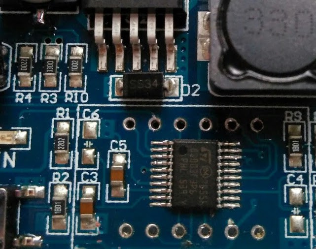
As expected the µC is a cheap STM8S003F3P6.I traced the wires and noticed the following:
- The NRST pin isn't connected (hence no ICP connector)
- PD1/SWIM drives segment G
- key "in" uses PD1/SWIM, too (I had noticed that when you press a key the display goes blank, now I know why)
- the LEDs "in" and "out" are segments A and B of a 4th digit (MPX PC3)
- key "out" uses PC3 (same as key "in" on PD1)
- PD2 and PD3 are the voltage inputs (or general GPIO)
- PB4 and PB5 (pins 11 and 12) are unused
Pin 5 of the LM2596 (/ENABLE) is connected to ground. It would have been easy to connect it to one of the unused µC pins. With thev ability to controll the converter key "in" wouldn't be useless (right now, it switches the voltmeter on or off while the output voltage is remains on).
Actually, that's is worse than useless - it's ridiculous!
You get what you pay for: assembled components without the engineering. I reckon that either the software was copied from some other circuit, or the SW-engineer isn't on the payroll anymore!
It goes without saying that I heated my soldering iron a second time: now PB5 controls pin 5 (/ENABLE) of the LM2596, and NRST is connected to the free pin 6 of the LED display socket. It turned out that the STM8S003F3P6 is read protected - but who cares?
Now what do we have? A bunch of assembled components that can be hacked into something useful!
- a relatively decent buck converter (even if the caps are of poor quality)
- a µC that can run Forth
- with an LM317 as a linear power supply
- with a 3 digit LED display
- with two keys (OK, pressing one of them will short-circuit the G segment)
- with two analog inputs (after removal of two resistors handily accessible on pads)
Possible applications (with more or less soldering effort) :
- a thermostat ;-)
- a battery charge controller
- on/off CV motor or solenoid control
- ...
For hacking the boards are just right. I ordered two more.
Discussions
Become a Hackaday.io Member
Create an account to leave a comment. Already have an account? Log In.
I have found a similar principle in a car (cigarette lighter socket) USB power supply. This had a display of input voltage, output current and temperature. Each of the analog inputs were connected to one of the display multiplex pins over resistor or voltage divider. The analog input voltages were scaled down to a range of 1V. Between the digits were brief pauses of 100µs were the pins were tri-stated and the ADC conversion was done. It was very confusing at first to have ~3,65V on the tap of a 33k / 2k2 voltage divider with 12V input - until I took the scope out.
So perhaps a similar strategy could be used with the button which shorts a segment out: Use a series resistor of several kOhm in series with the button and use a pull up (or down, depending on configuration) of several 10k Ohm. Then you can read the button in a short pause of the multiplexing.
Are you sure? yes | no
Hi Martin, you're right, double use of LED MPX with keys or analog sensors works well if designed properly, and at first glance such a circuit can be a bit confusing, too.
I'm sure that it wouldn't be difficult to improve the circuit, but in this project I would only consider it if it's an easily repeatable modification. In the case of the both the Chinese DCDC converters the copper traces are either rather narrow, or hidden under the LED display. However, I found that the usability impact of the LED display imperfection isn't really important.
If someone were to redesign the PCB considering a change like the one you proposed would be one of the first things on the agenda :-)
Are you sure? yes | no
That was a mistake :-) PD2 and PD3 are the voltage inputs. PD1 still has two or even three functions, though. Some boards don't have the all-but-useless key anymore, then it's two functions.
Edit: fixed PD1/PD2/PD3
Are you sure? yes | no
Good work, though I don't understand this:
"PD1/SWIM drives segment G" and "PD1 and PD2 are the voltage inputs"
The PD1 has somehow two functions?
Are you sure? yes | no