Close
0%
0%

The FPGA evaluation board - Frankenstein

In old PCB's i found a low-capacity FPGA(CPLD) - EPM7064. I decided to make a small evaluation board.

Public Chat
Similar projects worth following
In this project I tried to make the simplest FPGA board. Also, I tried to find real tasks that can be solved with the help of FPGAs of such small size.

Based on this board, I made several training projects. I'll post them a little later, as soon as I figure out how.

m7000[1].pdf

MAX 7000 - Programmable Logic Device Family

Adobe Portable Document Format - 1.45 MB - 09/06/2018 at 08:42

Preview

115ee92f1a38464ea83063d0be327782[1].gif

Digital Watch

Graphics Interchange Format - 1.40 MB - 09/06/2018 at 07:30

Preview

7f74f94e04cc4d53956f2e899a184327[1].gif

Sound generation

Graphics Interchange Format - 452.93 kB - 09/06/2018 at 07:29

Preview

3346cec6fac448bdbfc5125265b0b3f3[1].gif

Christmas lights

Graphics Interchange Format - 671.08 kB - 09/06/2018 at 07:27

Preview

  • 1 × Altera EPM7064 Small CPLD
  • 1 × Breadboard Electronic Components / Misc. Electronic Components
  • 1 × Wirewrap tool
  • 1 × TCO Generator 25 MHz
  • 1 × Wire Resistors (Fixed) / Zero Ohm Jumpers

View all 7 components

View project log

  • 1
    Scheme of board

    This is a prototype from scratch. Therefore, I did not make a scheme.

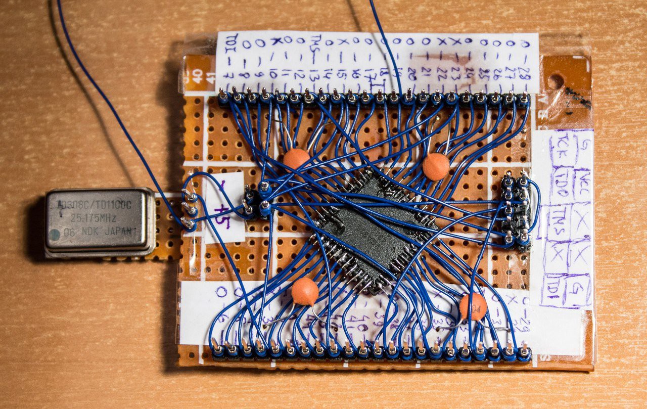
    I connected all the pins of the CPLD with the pins on the ends of the board. Instead of soldering, I used a wire wrapping. Soldered wires only to FPGA pins.

    I attached a description of each pin of the board. See PDF of MAX 7000 series.

    After that it became known to which pins to supply voltage. In FPGA are several VCC inputs. I combined them and brought them to a separate pin - VCC/GND, to which I will feed the entire board. The chip works from 5 volts. I shunted each separate VCC input with a capacitor.

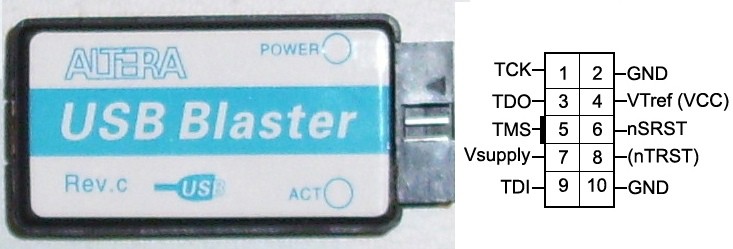
    Out of 10 pins, I made a programming connector. Attach pin description. With the wrapping, I connected the corresponding pins of FPGA and connector.

    A minimum of actions, but it is ready to work. It is already possible to flash the firmware and it can work singly.

    FPGA board - it's so easy! ;)

View all instructions

Enjoy this project?

Share

Discussions

smim72179 wrote 07/02/2021 at 08:07 point

Frankenstein is pretty close to me. I am glad that you raise this issue in your article. I can tell you that last week I needed to do an essay on the subject of Frankenstein and what I did, I turned to the guys for help https://blablawriting.com/essay-examples/frankenstein It's good that there are some really good quality essay examples for all kinds of topics.

  Are you sure? yes | no

Jarrett wrote 11/26/2018 at 19:37 point

it's beautiful

  Are you sure? yes | no

joe wrote 09/20/2018 at 21:19 point

great !!  nice to be unique :) 

  Are you sure? yes | no

Morning.Star wrote 09/19/2018 at 05:23 point

May the flux be with you. ;-D Nice work dude...

  Are you sure? yes | no

Dave_ Z. wrote 09/09/2018 at 08:36 point

amazing ^_^)))) Cat is a game changer

  Are you sure? yes | no

Dr. Cockroach wrote 09/06/2018 at 11:03 point

I love it, always liked hand wiring point to point. Great job on the soldering :-)

  Are you sure? yes | no

Alex wrote 09/06/2018 at 11:51 point

Thanks!

  Are you sure? yes | no

[deleted]

[this comment has been deleted]

Alex wrote 09/06/2018 at 11:54 point

Thanks! I do not have a soldering station. I work as an ordinary soldering iron with a copper bit.

https://habrastorage.org/files/9cb/2de/38d/9cb2de38d05a471babafc9b76d5f1022.jpg

  Are you sure? yes | no

MasterOfNull wrote 09/18/2018 at 17:30 point

I have one, but after I blew through my supply of tips, it got modified to use copper roofing nails.  Infinite supply of tips for like $5.  They wear out pretty fast if you leave the iron on due to the lack of a protective coating, but I don't think twice about grinding them to whatever shape I happen to need.

  Are you sure? yes | no

Jake Little wrote 09/19/2018 at 17:55 point

You can get an ultra cheap Hakko 936 clone control board, and a 936 style handle, for less than $3 usd each/shipped on AliExpress.

   You really want the iron to have a 60w element. The DC resistance of the element should be 9.5ohms to 10ohms max. If the resistance is 10.5 to 12 ohms the element is a 50w version, 12 to 13 ohms is a 40w and there are some mains voltage versions that will measure around 1k. I'm mentioning it because all of these elements look identical externally and Chinese sellers are bad about sending the wrong ones. You can build an adjustable iron for less than $10 this way.

 To be honest, I've tried the cheap hakko clone tips and I've made my own copper tips too (for 2 other irons). The real deal Hakko tips last much much longer than anything else, and they are much easier to use. your results will be much better. I highly recommend trying one to see for yourself. The only other thing you really really need when getting started is some good quality solder that is 0.8mm or smaller.  Most people use 0.8mm as the standard size on a work bench. Get reputable solder and be sure it is leaded. Leadfree is a joke, it is terrible stuff to work with.

The 936's are all powered by a 24 volt transformer or SMPS. You can use an old laptop or printer power brick rated for 3-4 amps. If the voltage of the supply is a little bit off, there's a video on youtube that shows how to modify the voltage here:

https://youtu.be/5uiQjes-a98

  Are you sure? yes | no

Similar Projects

Does this project spark your interest?

Become a member to follow this project and never miss any updates