 SCART VADER
Disclaimer: Use the information provided here at your own risk. I do not take any responsibility for any resulting damage.
1 Pin outs
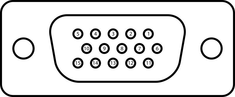
PIN # |
name | description |
|---|---|---|
| 1 | RED | Red video |
| 2 | GREEN | Green video |
| 3 | BLUE | Blue video |
| 4 | ID2/RES | formerly Monitor ID bit 2, reserved since E-DDC |
| 5 | GND | Horizontal sync ground |
| 6 | RED_RTN | Red return |
| 7 | GREEN_RTN | Green return |
| 8 | BLUE_RTN | Blue return |
| 9 | KEY/PWR | formerly key, now +5V DC, powers EDID EEPROM chip on some monitors |
| 10 | GND | Vertical sync ground |
| 11 | ID0/RES | formerly Monitor ID bit 0, reserved since E-DDC |
| 12 | ID1/SDA | formerly Monitor ID bit 1, I²C data since DDC2 |
| 13 | HSync | Horizontal sync |
| 14 | VSync | Vertical sync |
| 15 | ID3/SCL | formerly Monitor ID bit 3, I²C clock since DDC2 |
Table 1: Pin out of a female DE-15 connector functioning as a VGA output from wikipedia
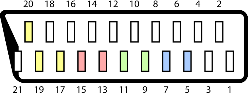
PIN # |
description |
|---|---|
| 1 | Audio output (right) |
| 2 | Audio input (right) |
| 3 | Audio output (left/mono) |
| 4 | Audio ground |
| 5 | Blue ground |
| 6 | Audio input (left/mono) |
| 7 | Blue |
| 8 |
Status & Aspect Ratio 0–2 V → off +5–8 V → on/16:9 +9.5–12 V → on/4:3 |
| 9 | Green ground |
| 10 | not used in this project |
| 11 | RGB Green |
| 12 | not used in this project |
| 13 | Red ground |
| 14 | pin 8 ground |
| 15 | Red |
| 16 |
RGB selection 0–0.4 V → composite 1–3 V → RGB |
| 17 | Composite sync ground |
| 18 | pin 16 ground |
| 19 | Composite sync output |
| 20 | Composite sync input |
| 21 | Shell/Chassis |
Table 2: Pin out of a SCART connector from wikipedia
2 Power source
Many components used in this project require a 5V power source. You have several alternatives:
- If you are generating the VGA signal using a PC you can get it from its internal power supply. You can see the pin out here.
- If the system used to generate the VGA signal has USB ports you can get it from one of them. You can see the pin out here.
- You can use an external power supply. Any cell phone charger with an USB connector should be adequate.
- If the device generating the VGA signal is not very old it will probably provide 5V through the pin 9 of the DE-15 connector. If it complies with the DDC host system standard it will supply at least 300 mA, which is enough to power all the components used in this project.
3 Horizontal frequency monitoring
As mentioned, the frequency of the horizontal scanning of a CRT TV is about 15.7 KHz. If the frequency composite sync signal is higher the image will not be properly displayed, but it will probably not damage your TV since the actual scanning movement of the electron beam is directed by internal deflection generators. However, if you are using a very old monitor or just do not want to be annoyed by a messed image you can use a circuit to blank the screen when the horizontal frequency is not correct. You can see these circuits in Tim Worthington's guide. I have not tested it, but I suggest you to use the solution based on the PIC12C508 since it has only a few connections to solder. The PIC will monitor the horizontal sync signal and will generate a logic output called ENABLE. If the horizontal frequency is OK the PIC will set ENABLE high. Otherwise it will set it low. This ENABLE signal can be used in several ways:
- Blank the screen by setting the RGB selection signal to ground when the frequency of the horizontal sync signal is wrong
- Disable the composite sync signal when the horizontal sync frequency is too high
- If a DC-DC converter is used to generate the status signal, shut it down
The use of the ENABLE signal is described bellow....
Read more »
 helge
helge
 kamalkedin123
 Adrian Freed
 Nick Sayer
Thank you, visenri. I followed your instructions and redesigned it with a PIC16F18313. It works! Now the PIC itself generates the 9.5-12V signal. I will publish the new design ASAP.