 Alastair Young
-
1Controllers
The controller that comes with the Elekslaser is the EleksMaker® ManaSE (version unclear) which is an arduino nano and supports two A4988 driver modules. I am using this to control the C axis and may use it's motor port - spindle speed - to control some lights or something. This board keeps the motors permanently enabled - it has the driver ENA pins hardwired to the 5V rail. I think this may overheat the little Nema8 motor, so rewiring or replacement of this board may be in order.
The 4 driver arduino shield is a copy of the Protoneer V3.00 which is GRBL compatible. The fourth driver is jumpered to clone the Y axis as it is a two-motor axis. GRBL only does 3 axes on the Atmega328p. The X-Y is configured with the setting from the Elekslaser (80 steps/mm at 16X microstepping) and the Z is set at 100 steps/mm which is 1X microstepping on a lead screw with a 2mm lead.
Both controllers are running the current GRBL 1.1
I haven't verified that the new controller will actually drive the laser system yet, that will need rewiring. I have swapped pins 11 & 12 between the arduino and the shield as these pins were swapped by GRBL after the protoneer 3.00 board was designed.
I disabled soft limits as I kept going outside them and freezing the board. The motors are weak enough they will just make noise and miss steps if they crash, so I'd rather just re-home when that happens.
I have a third arduino on the bus, a nano with a Funduino shield which is intended to control lights, air solenoids, vacuum pump etc, the idea being I would take GRBL and strip out the XYZ to make space for more pin controls, vacuum sensors, neopixel lights etc keeping the GCODE interpreter and pin code. Now I'm thinking I'll just strip Y and Z and keep the X to drive the C axis and junk the Eleksmaker board. Need to look for a single stepper driver shield on the cheap if I do that. Or I drive the Y off one driver and use the 4th driver on the protoneer-clone via its external pins.
XYZ Settings
$0=10
$1=25
$2=0
$3=3
$4=0
$5=0
$6=0
$10=1
$11=0.010
$12=0.002
$13=0
$20=0
$21=0
$22=1
$23=3
$24=25.000
$25=3000.000
$26=250
$27=1.000
$30=1000
$31=0
$32=0
$100=80.000
$101=80.000
$102=400.000
$110=8000.000
$111=8000.000
$112=1000.000
$120=400.000
$121=400.000
$122=10.000
$130=350.000
$131=250.000
$132=46.000C Settings (under development)
$0=10
$1=25
$2=0
$3=3
$4=0
$5=0
$6=0
$10=1
$11=0.010
$12=0.002
$13=0
$20=0
$21=0
$22=1
$23=3
$24=25.000
$25=3000.000
$26=250
$27=1.000
$30=1000
$31=0
$32=0
$100=80.000
$101=80.000
$102=400.000
$110=8000.000
$111=8000.000
$112=1000.000
$120=400.000
$121=400.000
$122=10.000
$130=350.000
$131=250.000
$132=46.000 -
2Z axis
The z axis is a 9MN Miniature Guide Linear Support Rail Slide Bearing Steel Ball Holder/Retainer (175mm) . This as a flat rail with ball race up each side and a sled. The whole thing is only 8mm deep.
8mm lead screw and nut - 2mm lead driven by a Nema8 stepper. Yes it is small, but we are not driving a lot of weight here. Idrives the Z-axis load without problems.
The springy 4mm/8mm coupler came with a wildly off 4mm hole. However as I have a lathe and just acquired some metric reamers I was able to re-sleeve it straight.
Total spend there for Z axis - $31 including shipping so I have something at half the price and much more compact than the commercial options.
The z-axis stepper is be mounted on the Y carriage with aluminum angle salvaged from an old datacenter keyboard tray (also used in my reflow oven project - don't throw stuff away!). The carriage is from the same material.
I used part of a nano scre-shield board to make a converter board to convert from the tiny 6-pin connectors on the Nema8s to the the 4-pin cables.
The homing switch is a makerbot.com design attached with a foam-tape and nano-screw-shield offcut 5 layer sandwich. This comes with a 5V power line that is currently unconnected
-
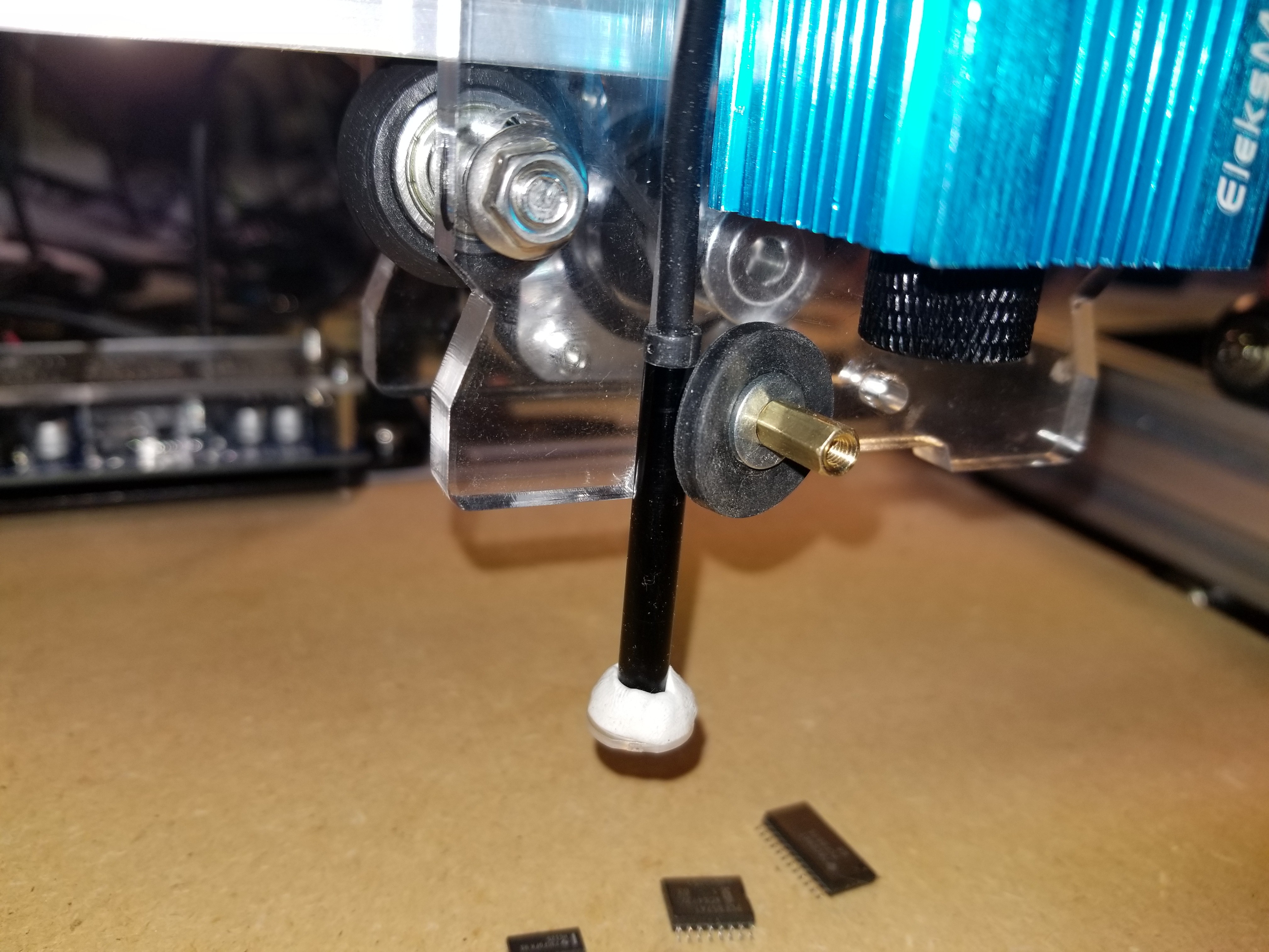
3C axis
Hollow shaft Nema-8 stepper with built in nipple. I think the nipple was a mistake, as I had not considered the swiveling requirements. The swivel is a 5mm bore sealed ball bearing which would have been a close slip fit on the 5mm shaft, but wobbles on the nipple. I could have just epoxied it onto the straight shaft. As it is I used two #60 o-rings and then trimmed them down with a knife. The bearing is pushed into a piece of delrin with a hole in the other end where the tube pushes in. The vacuum tube has a guide above it (paint stirrer and foam tape) to keep the tube straight - this keeps down the friction and twisting effects on the stepper.
-
4Nozzles, Adapters and Quick-change
Googling around suggested to me that I want the Juki nozzles as they come with some springiness in the tip. This will allow for a good seal even if the Z is a little off. They do cost a little more than the Fuji.
There is an excellent looking quick-change head for these for $40, which involves springs and ball bearings, but I also came across a post showing a simpler one that someone chanced together that just uses magnets. You would think that that would make the tip magnetic - bad thing - but it didn't. When one of the magnets dropped off - then it became magnetic. Light bulb. By placing the magnets on either side with their polarity in the same direction i.e one has North into the nozzle and the other has South into the nozzle they hold the nozzle but the magnetic field does not propagate down the shaft of the axis.
See wikipedia
![]()
After a dry run with scrap bronze and a couple of attempts in Delrin - with the second attempt using a collet and reamers - I think I have the quick change nozzle done.
Two videos. First shows the operation and the run-out from not using collet and reamers, and the second one shows the minimal run-out on the final version.
And another view from the up camera. I think I can get the runout down a bit more, but I'm hoping this will be good enough, even for 0603
-
5Cameras
ELP modules appear to be the recommended thing. Not the cheapest things at $25 a pop, plus lenses.
I'm going with a cheaper alternative - random eBay endoscopes with corrective lenses salvaged from a scrap disposable camera. This combo seems to be good for filling the screen with my largest chip - SOIC-24 and still see 0603 clearly. I can barely see 0402's so I don't think I'll be going there.
The endoscopes came from https://www.ebay.com/itm/272969087508 - under $15 for two.
The disposable camera was a Fuji Quicksnap which has been sitting in a drawer unopened and had a develop-by date 9 years ago. Call that free.
Lenses are were originally attached with Sugru moldable glue but that was ditched in favor of more solid solutions.
These cameras are YUV only, no MPEG, so need to be plugged into opposite sides of the laptop to get separate USB host controllers.
One of these is now mounted in the Y carriage by clamping against a vertical groove.
![]()
The Sugru lens mount shown has been rplaced with a litle piece of orange plastic I found on the floor. The lens is welded to this (soldering iron) and the plastic is screwed onto the camera by drilling a hole that almost goes in and then twisting it on
These seem to work best at 28mm
The UP camera is mounted in a door-peephole I found in my scrap box. These are a fish-eye design, but when you dismantle them there are concave lenses and one convex lens nearest the eye. This convex lense is right for the macro, so I drilled the center of the outer concave lens to the concave was a press fit into it and then mounted the camera in a delrin sleeve inside the case. This gives a nice solid mount perpendicular to the table - after a little shimming.
-
6Feeders
For cheapness, feeding using the nozzle is the way to go, which works only for the small nozzles and probably bad for the rubber tipped ones.
Laying the strips flat will be the initial method - the spool thing is a luxury item.
-
7X-Y Axes and Base
This is the EleksMaker® EleksLaser-A3 Pro with the laser module removed. This is a belt-walk system (belt is stationary and acts as a rack).
This has been raised up 75mm to keep the electronics underneath and MDF acquired for a base and work surface. The work surface has thin sheet steel glued to it to allow magnetic fixtures to be used.
-
8Computer
I've revived a 6 year old HP Envy 15 laptop. This was daughter #1's off-to-college machine and is pretty nice. Full HD screen, Intel I7 quad core processor and 8G of RAM. It had been shelved because of a problem with the Radeon graphics controller freezing the machine whenever it was enabled. This would make it fine for an office system except Windoze insists on running update all the time and re-enabling the card half way through.
Debian installed just fine. I think it did freeze on first boot after install, but I figure it did the sensible thing and marked the Radeon as bad and stopped trying to use it.
OpenPnp also installed without incident following the instructions.
It can talk to both cameras albeit from ports on opposite sides of the machine - because the cameras are stupid cheap ones that don't do MPEG. Also the down camera always has to be unplugged and re-plugged bore it works - some weird USB addressing thing.
-
9GCODE, homing etc
OpenPNP comes with G28 as the default homing thing, but that did not work for me.
What I ended up with is as follows, with comments:
- CONNECT_COMMAND
- $X ; unlocks GRBL as we have homing cycle $21=1 enabled
- G90 ; Switch to absolute distance mode
- G21 ; After this, units will be in mm
- HOME_COMMAND
- $H ; run homing cycle. This will set us 3mm off the switches.
- G28 ; go to location saved in G28.1 - approx location of the vision homing fiducial
- G92 X0 Y0 Z0 ; makes the current position the workspace origin
- POST_VISION_HOME_COMMAND
- G92 X39 Y15 Z23 ; makes the current position X39, Y15, Z23
- G0 X0 Y0 Z0 ; move to the current zero
There is machine.xml settings for telling openpnp to look for the homing fiducial at an X-Y offset, but I kept crashing the machine trying to get that to work. What I ended up doing is to not use that but run the grbl homing routine and then have G28 move it to the machine offset where it can find the homing fiducial (G28 is a machine coordinate thing, not a workspace coordinate thing) and then set workspace coordinate 0,0,0 there and let it do its visual homing thing.
Once it has completed visual homing, which leaves OpenPNP thinking it is at 0,0,0 on the DRO, redefine the workspace origin to be back near the homing switches and then move over there.
The homing fiducial is a white dot on a black background printed on my Dymo label printer.
- CONNECT_COMMAND
Thrifty Pick and Place
Building a Pick and Place machine on the cheap, in a repeatable way.

Discussions
Become a Hackaday.io Member
Create an account to leave a comment. Already have an account? Log In.